1
Installation Instructions:
DO NOT INSTALL DURING ACTIVE STORM CONDITIONS.
Note: It is important to keep all connecting leads as short as
possible. Additionally, conductors should be twisted together
for as much of the wire run as possible.
1. Ensure power to the panelboard has been removed.
2. Remove the screws securing the outer panelboard
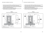
cover to the panelboard (see Figure 1).
3. If SPD has optional flush mount kit (FMKITC)
please follow instructions provided with the
SPD4Flush and then proceed to #4 in this manual.
4. Select the location where the SPD4home will
be mounted (should be based on the internal
configuration of the panelboard and the
physical surroundings outside the panelboard).
Note that the SPD4home’s lead length must be
minimized to achieve maximum performance.
Once the location and threaded connection has
been determined, drill or punch an appropriate
size hole in the top, bottom or side surface of
the panelboard. The ideal mounting location
will also allow the SPD4home to be secured to
the wall or panel in addition to using a chase
nipple or short threaded pipe.
5. Push the leads from the SPD4home through
the hole toward the inside of the panelboard.
Secure the SPD4home to the panelboard.
6. If possible, to provide extra rigidity in the
installation, attach the SPD4home to the wall or
panel using installer supplied hardware.
7. Trim the leads from the SPD4home as short
as possible, but still allowing the following
connections to be made (see Figure 1):
▪▪ Black wires go to the nearest free 20 Amp 2
pole circuit breaker. The phase of each lead is
marked with a white band and letter designator (L1 or L2). Connect the SPD4home leads
to the appropriate phases. (In all installations,
Always install the SPD4home on the load
side of the main disconnect
Figure 1: SPD4home
Mounting Screws
(4 places, not supplied)
Installation Wiring Diagram
for WYE Applications
Interconnecting Wiring
· Minimize length
· Avoid Sharp Bends
Integral Chase Nipple
(nut installed)
Chase Nipple Nut
20 Amp
Breaker
Wiring to Breaker:
L1- Black
L2- Black
Outer Breaker Panel
Cover Screws
(6 places, typical)
Panelboard
Wiring to Neutral or
Ground Bus:
Ground - Green
Neutral - White (if used)
it is not critical which black wire goes to the
positions on the circuit breaker.)
▪▪ Connect the white Neutral wire to the neutral
bar using a set screw (in some applications,
this connection may not be required).
▪▪ Connect the green Ground wire to the panelboard ground.
8. Install the panelboard cover. Note: Conducting
dielectric and/or high potential testing will
cause internal damage to the SPD4home
unit. DO NOT perform dielectric or high
potential tests with the phase or neutral
SPD4home wires connected.
9. Apply power to the panelboard. The two
LEDs will illuminate on the SPD4home. If
any connected phase LED on the SPD4home
does not illuminate, remove power, check all
connections and test again. If any connected
phase LED still does not illuminate, contact
Siemens Technical Support 1-888-333-3545.
Operation
The Siemens Residential surge suppressor normally
requires no remedial action. However in the event of
a power anomaly or a malfunction, the operational
status may change and may require action.
The table below outlines the operating conditions of
the TPSA9040 and any correction action if required.
Light
1
Light
2
Alarm
Red
Audible
Alarm
Corrective
Action
Out
Out
Out
Off
Reset Breaker if Breaker
Trips Replace Unit
Green
Green
Out
Green
Blinks
Sounds
Replace Unit
Green
Out
Blinks
Sounds
Replace Unit
Green
Green
Blinks
Sounds
Check Neutral to
Ground Connection
before Replacing Unit
No Action
This device features internal circuitry that will
disconnect the surge protective component at the
end of its useful life. Power will maintain to the load,
however the load is now unprotected. Follow the
manufacturer’s instructions for replacing the device.
Siemens Industry, Inc.
5400 Triangle Parkway
Norcross, GA 30092
888-333-3545
[email protected]
www.usa.siemens.com/spd
Metal Wall of Panelboard
2