1
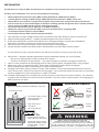
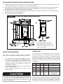
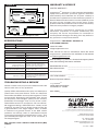
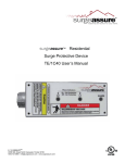
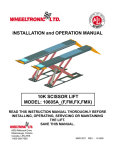
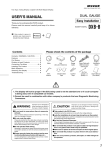
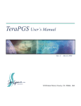
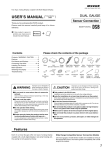
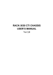
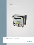
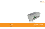
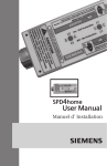
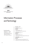
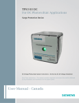
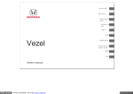
INSTALLATION MANUAL
SA
Series
Residential
Surge Protective Device (SPD)
INTRODUCTION
Thank you for choosing the surgeassureTM SA Series
Residential Surge Protective Device.
on electrical distribution equipment capable of
delivering not more than 25,000 rms symmetrical
amperes.
Save this manual! It includes instructions for obtaining
warranty service and for returning a defective device.
During installation into an electrical system, the SA
Series must NOT be energized until the electrical
system is installed, inspected and tested. All
conductors must be connected and functional.
Please read and understand all information in this
manual prior to installation. The procedures contained
herein are not intended to supersede local or national
electrical codes. Check all applicable electrical codes to
ensure compliance. In all instances, local and national
electrical code requirements are to be followed.
Failure to follow the guidelines in this manual can lead
to abnormally high voltage being applied to the
SPD. This may cause the SA Series unit to become
inoperative. The warranty does not cover an
incorrectly installed device.
This manual provides instructions for installing the
SA Series Surge Protective Device (SPD). The SA
Series SPD (Figure 1) can be mounted three ways.
The preferred way is to mount the SPD directly to the
outside of the electrical panel equipment using the
chase nipple on the body of the SPD. It can also be
installed against a panel/wall using installer supplied
hardware, or it can be installed using an optional
Flush Mount Kit. The latter two methods require use
of additional conduit and hardware (not provided).
The SA Series provides protection from damaging
transient voltage surges and spikes. Proper installation
is imperative to maximize the effectiveness and
overall performance of this device. This device must
be installed by a licensed electrician. The electrician
should follow the steps outlined in this manual to
insure proper installation.
Note: surgeassureTM products are extensively tested
to industry standards as set by ANSI/IEEE C62.41.12002, C62.41.2-2002 and C62.45-2002. The SA
Series is listed to the most recent edition of UL 1449
Third Edition. This product is suitable for installation
14550 58th Street North
Clearwater, Florida 33760
Do not high potential test the electrical system with
the SPD connected. Failure to disconnect the SPD
during elevated voltage testing will result in damage to
the suppression components and/or other electronic
components (see Safety Information).
PARTS LIST AND INSPECTION
Items included in the package consist of the following:
1 SA Series Surge Protective Device
Data Sheet
1 User’s Manual (this document)
▪
▪
▪
If the Flush Mount Kit (Part #FMKITC) was ordered,
additional parts are supplied as follows:
▪ 1 Flush Mount Plate
▪ 4 Pan-head Screws
See Figure 3 for installation
Carefully inspect each item in the package for signs
of damage. If damage is found, please contact
surgeassureTM Technical Support: 1-800-727-0669.
For more information about this product or other
surgeassureTM products, visit surgeassure.com.
Tel: 1.800.727.0669
Fax: 727.539.8955
[email protected]
www.surgeassure.com
A Division of Advanced Protection Technologies, Inc. APT’s Quality Management System is ISO 9001:2008 Certified
INSTALLATION
The SA Series is a Type 2 SPD. The SA Series is suitable for use downstream of the service disconnect.
Pre-Plan your installation. You need to accomplish the following:
▪
▪
▪
▪
▪
▪
▪
Meet all National and Local codes (NEC® Article 285 and UL 1449 address SPDs).
Confirm System voltage to SPD voltage (120V SPD will fail instantly on 240V, 277V, etc.).
Mount SPD as close to panel or equipment as possible to keep leads short. (long leads hurt performance).
Ensure leads are as short and straight as possible, including neutral and ground. Use a breaker position
that is close to the SPD and the panel’s neutral and ground.
Recommended breaker size is 30A due to 10 AWG conductor.
Make sure system is grounded per NEC® and clear of faults before energizing SPD.
(inadvertent system problem may fail SPD).
Never Hi-Pot test Any SPD. (will prematurely fail SPD).
1. Use voltmeter to check voltages and ensure correct SPD. See Data Sheet for specs and wire-outs.
2. Determine Mounting location – weather resistant equipment may be required.
3. If SPD has optional Dry Contact Flush Mount Kit, or Remote Indicator, pre-plan their installation.
See Figure 3. (If flush mounting, be careful to not drop SPD into wall).
4. Remove power from panel/source. Confirm panel/source is deenergized.
5. Identify breaker location and SPD location. Position SPD such that LEDs are best visible.
If Flush Mount Kit was ordered, follow Flush Mount instructions and then proceed at #6.
6. Mount SPD – weather resistant applications require additional sealing, etc. (not included)
- Remove an appropriately sized knockout from panel.
- Connect conductors as appropriate – short and straight as possible (Hi-Legs are Phase B).
7. Label or mark conductors as appropriate (neutral: white, ground: green, energized: black, hi-leg: orange).
8. Make sure system is bonded per NEC® and is clear of hazards or faults before energizing
(N-G bonding not per NEC® will fail SPDs: #1 cause of SPD failures).
9. Energize and confirm proper operation of green LED indicators. If any connected phase LED does not illuminate, remove power, check all connections and test again. If any connected phase LED still does not illuminate,
contact surgeassureTM Technical Support at: 1-800-727-0669.
10. The SPD is equipped with an audible alarm which will sound in the event of an alarm condition. This indicates
a problem with the SPD which requires further evaluation. There is no test or silence switch. De-energizing the
SPD will silence the alarm.
TYPICAL PANEL INSTALLATION
Figure 1
Figure 2
LEADS SHORT & STRAIGHT
(T y p e 1 o r i n d i v i d u a l e q u i p m e n t i n s t a l l a t i o n s m a y v a r y )
Cu t o f f
Exce
s
Le n g t h
T o P r o t e c t e d Lo a d s
▪
▪
A
B
▪
BREAKER
N
▪
G
Use
cl o se
st
b r e a ke
Lo ca t e SP D lc o es
i n t e n d e d b r e a ek r
D o No t
Lo o p o r
Co i l
r t o SP D
to
Sh o r t &
St r a i g h t
K e e p Le a d s Sh o r t
a s P o si b l e
Avo
i d Sh a r p B e n d s
ph 800.727.0669 • www.surgeassure.com
8815
Surge Protective Device
ALARM
ALARM
2 Green LEDs On
= Full Protection
2 Green LEDs On
= Full Protection
Surge Protective Device
ph 800.727.0669 • www.surgeassure.com
▪
▪
2
Ro t a t e SA u n i t s u c h t h a t
LED i n d i c a t o r i s m o s t v i s i b l e
Ou t d o o r i n st
a p p r o p r ia te
a t n i p p l e (g a
co n d u i t , e t c.
a lla tio n r e q u ir e s
w e a t h e r se a l i n g
ske
t , se a l i n g
)
V
WARNING
V ERIF Y T H AT ALL P OW ER CIRCUIT S ARE
D EENERG IZ ED B EF ORE MAK ING CONNECT IONS
All electrical connections should be performed by a qualified
(l i ce n se d ) e l e ct r i ci a n o r t e ch n i ci a n . Al l w i r i n g m u st co m p l y w i t h
t h e Na t i o n a l El e ct r i ca l Co d e (NEC® ) a n d a p p l i ca b l e l o ca l co d e s.
FLUSH MOUNT INSTALLATION INSTRUCTIONS
1. Select the location where the SPD and Flush Mount Kit (XMFMKIT) will be mounted. Aesthetics may have
to be sacrificed in order to achieve maximum surge protection.
2. Place the Flush Mount Kit plate where it will be mounted and trace the center hole and mounting holes.
Cut this shape into the mounting surface and mount the XMFMKIT panel to the mounting surface
3. BE CAREFUL TO NOT DROP THE SPD INTO THE WALL.
4. Install the SPD to the back side of the Flush Mount Kit plate using the four 8/32 x 5/8” Thread Cutting
Screws provided with the XMFMKIT kit.
5. Proceed with #6 on previous page.
Figure 3
TYPICAL SA SERIES SPD INSTALLATION
*
SAFETY INFORMATION
This section provides pertinent safety information
that must be considered before installing the SPD.
▪
▪
▪
▪
Do not install this device during a lightning storm.
This device is rated NEMA 4X. Suitable for indoor
and outdoor applications. The customer must
seal the conduit nipple against the panel using
watertight fittings (not supplied) to ensure a
watertight connection.
Do not install the surge protector in an excessively
hot or moist location.
Other safety considerations are listed on the
previous page.
CAUTION
COND UCT ING D IELECT RIC AND / OR H IG H P OT ENT IAL
T EST ING W ILL CAUSE INT ERNAL D AMAG E T O T H E
SP D UNIT . D O NOT P ERF ORM D IELECT RIC OR H IG H
P OT ENT IAL T EST S W IT H T H E P H ASE OR NEUT RAL SP D
W IRES CONNECT ED .
Insert flushmount screw through
hole in each corner or punch a
small starting hole in center of each
translucent window (located in all 4
corners of the label).
OPERATION
The surgeassureTM Residential surge suppressor
normally requires no remedial action. However in
the event of a power anomaly or a malfunction, the
operational status may change and may require
action. The table below outlines the operating
conditions of the SA Series and any correction action
if required.
Light 1 Light 2
Out
Out
Alarm
Red
Audible
Alarm
Corrective Action
Out
Off
Reset Breaker if re-opens
Replace Unit
Replace Unit
Green
Green
Out
Green
Blinks
Sounds
Green
Out
Blinks
Sounds
Replace Unit
Sounds
Check Neutral to Ground
Connection before
Replacing Unit
Green
Green
No action
Blinks
This device features internal circuitry that will
disconnect the surge protective component at the
end of its useful life. Power will maintain to the load,
however the load is now unprotected. Follow the
manufacturer’s instructions for replacing the device.
3
Figure 4
WARRANTY & SERVICE
DIMENSIONS & WEIGHT
LIMITED WARRANTY
8.28
(210.31)
7.41
(188.21)
8.28
(210.31)
ph 800.727.0669 • www.surgeassure.com
7.41
(188.21)
8815
ph 800.727.0669 • www.surgeassure.com
8815
Surge Protective Device
2 Green LEDs On
= Full Protection
Surge Protective Device
ALARM
2.21
(56.13)
2 Green LEDs On
= Full Protection
3.67
(93.22)
ALARM
2.21
(56.13)
ALARM
2 Green LEDs On
= Full Protection
ALARM
2 Green LEDs On
= Full Protection
Surge Protective Device
Surge Protective Device
ph 800.727.0669 • www.surgeassure.com
ph 800.727.0669 • www.surgeassure.com
0.19
(4.83)
T h e SA Se r i e s w e i g h t i s 4 l b s.
XM
SPECIFICATIONS
Model
LH
LF
DMP
XM
3.67
(93.22)
The company specifically disclaims all other
warranties, expressed or implied. Additionally, the
company will not be responsible for incidental or
consequential damages resulting from any defect in
any product or component thereof.
3.00
(76.20)
0.19
(4.83)
surgeassureT M warrants it’s AC electrical distribution
equipment protection products against defective
workmanship and materials for 10 years. Liability is
limited to the replacement of the defective product. A
Return Material Authorization number (RMA #) must
be given by the company prior to the return of any
product. Returned products must be sent to the factory
with the transportation charges prepaid.
10.7.13
10.7.13
10.7.13
8609
XM SERIES
ENCLOSURE
T
surgeassure
05A8609
-
M
TECHNICAL SUPPORT &
CUSTOMER SERVICE
Voltage Rating & Service
Type XM SERIES
LH
10.7.13
LF
SA
10.7.13
120/240V Single Phase
DMP 10.7.13
ENCLOSURE
8609
05A86091.800.727.0669
-
Specifications
Temperature Operating
-40°C (-40°F) to +60°C (+140°F)
Temperature Storage
-55°C (-65°F) to +65°C (+149°F)
Audible Noise
Service Clearance
Installation Type
Wire Length vs.
Response Time and
Let-Through Voltage
Wire Size & Installation Torque
Circuit Breaker Connection
System Grounding
None
36 in (94.1 cm) in front of the unit
Chase Nipple
1 ft (31.7 cm) of wire = 1
nanosecond. 175 volts per foot
(6kV,3kA, 8/20 microseconds) are
added to the clamp voltage.
in fo @
s u r g e a s s u r e .c o m
T h is m a n u a l a s w e ll a s in fo r m a tio n a b o u t th e e n tir e
M
p r o d u c t l i n e a r e a v a i l a b l e o n t h e In t e r n e t
a t : w w w .s u r g e a s s u r e .c o m .
surgeassureT
P r i o r t o c a l l i n g surgeassureT M f o r t e c h n i c a l s u p p o r t , p l e a s e
h a v e th e fo llo w in g in fo r m a tio n a v a ila b le :
Mo d e l Nu m b e r o f u n i t : _ _ _ _ _ _ _ _ _ _ _ _ _ _ _ _ _ _ _ _ _ _ _ _ _
Wire Size = #10 AWG,
torque to 18 in. lbs.
Ma n u f a c t u r e D a t e :
30 Amp
P u rc h a s e D a te :
Per IEEE STD 142-1991. For sensitive
electronics/computer systems, the
recommended ground impedance
is 25 ohms or less.
_ _ _ _ _ _ _ _ _ _ _ _ _ _ _ _ _ _ _ _ _ _ _ _ _
TROUBLESHOOTING & SERVICE
Y o u r Or d e r Nu m b e r :
_ _ _ _ _ _ _ _ _ _ _ _ _ _ _ _ _ _ _ _ _ _ _ _ _
_ _ _ _ _ _ _ _ _ _ _ _ _ _ _ _ _ _ _ _ _ _ _ _ _
Re t u r n Sh i p m e n t Ad d r e s s :
surgeassureT
M
Please contact us for any service related issues. We
want to take care of any problems.
14550 58t h St r e e t No r t h
Cl e a r w a t e r , F L 33760
Quality SPDs withstand severe duty and attempt to
protect their load until failure. There are electrical
anomalies that SPDs cannot protect against. These
are generally Sustained Overvoltages also known
as Temporary Overvoltages (TOVs). In this context,
Sustained Overvoltages may be only a few cycles.
Failed SPDs tend to be symptoms, not root causes.
We suggest treating a failed SPD as a ‘canary in the
coalmine’ as there may be larger issues at play. As
a generalization, the single largest ‘killer’ of SPDs
is reference to ground issues. If the SPD shows
problems on startup, there is reasonable chance
of bonding/grounding/misapplication issue. This
permanently damages the unit. If not corrected, it
will happen again.
At t n : RMA# _ _ _ _ _ _ _ _ _ _ _ _ _ _ _ _ _ _ _ _ _ _
Any returns need a Return Authorization (RA)
number.
4
A Division of Advanced Protection Technologies, Inc.
APT’s Quality Management System is ISO 9001:2008 Certified
14550 58th Street North
Clearwater, Florida 33760
Tel: 1.800.727.0669
Fax: 727.539.8955
[email protected]
www.surgeassure.com
2.17.15.lh #8817