1
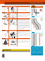
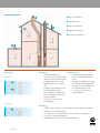
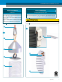
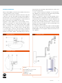
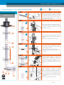
BK-CG-102 • 891153
WARNING
Improper installation of Vent System and Components, or failure to follow installation instructions, can result in property damage or serious injury.
-
Examine all components for possible shipping damage prior to installation;
Proper joint construction is essential for a safe installation. Follow these instructions exactly as written;
This venting system must be free to expand and contract. This venting system must be supported in accordance with these instructions;
Check for proper joint when joining pipe to fittings;
Check for unrestricted vent movement through, walls, ceilings, and roof penetrations;
Different manufacturers have different joint systems and adhesives. Do not mix pipe, fittings or joining methods from different manufacturers
Installation Manual
Z-DENS™
Flex
Single Wall
Venting ULC-S636 / Class IIC- Max.110°C
Installation Manual CoxDENS® PPs Flex
CONTENTS
Introduction
3
Installation Requirements
3
Approvals/Codes
3
Product specifications
3
CoxDENS PPs Flex Components
®
General installation conditions
3
3
Installation of the CoxDENS PPs Flex system through a masonry chimney
5
Condensing solutions
8
Wall plates
8
Installation Details
9
®
Pull-in tool
Coupling and inspection piece
Chimney cover
9
9
Dealing with Condensate
10
11
Maintenance
12
2
10-1-2013
INTRODUCTION
Product specifications
•
Single wall CoxDENS® PPs Flex is third party certified to ULC-S636
Flexible Vent pipes made of flame retardant Polypropylene
material (certified for use flue gas in accordance with a
standard for Class IIC rating (exhaust temperatures up to 110°C
European standard DIN EN14471). Not UV resistant;
(230°F)) and CE EN 14471. Certified diameters are 60mm (2”),
•
Sealings are made of Viton;
80mm (3”), 110mm (4”). The following installation instructions are
•
Supports of galvanized steel;
in accordance with the requirements of section 4 of the ULC-S636
•
Cox Geelen Pipe lubricant Chloride free;
Standard.
•
System diameters: 60mm (2”), 80mm (3”), 110mm (4”);
•
Shaftcover:
Single wall CoxDENS® PPs Flex is a vent system for type BH
Gas-Venting, for use with ANSI Category II and IV gas burning
appliances (condensing boilers) with a max flue gas temperature
of 110°C.
-Cover house is made from HDPE in the colour RAL9005
(Black)
-Termination pipe is made from UV-stabilized Polypropylene material;
-Gasket is made of EPDM in the colour RAL9005 (Black);
In addition, please refer to the appliance manufacturer’s
-Birdmesh made of stainless steel;
instructions for restrictions to the total vent length or height,
number of elbows that can be used, sizing of the vent or specifics
COXDENS® PPs FLEX COMPONENTS
as to appliance connections before proceeding with the installation
take precedence over this document.
For a list of ULC-S636 approved CoxDENS® PPs Flex
components, please consult the CoxDENS® PPs Flex catalogue
at www.coxgeelen.com.
INSTALLATION REQUIREMENTS
General installation conditions
of this product. Appliance manufacturer’s installation instructions
Installation and Annual servicing of the CoxDENS® PPs Flex vent
system must be performed by a qualified installer, service contractor
1. Do not install CoxDENS® PPs Flex in areas where
ambient air temperature exceeds 150°C (302°F).
or gas supplier. The safe operation of a system is based on the use
of parts supplied by the manufacturer and the performance of the
2. Do not store the CoxDENS® PPs Flex system in a
system may be affected if the combination of these parts is not
corrosive environment and keep protected from UV light
used in the actual building construction. Acceptance of the system
(ideally in its packaging).
is dependent upon full compliance with the installation instructions.
3. The maximum continuous vertical vent length is 30m
(98’). Always refer to the manufacturer’s instruction for
appliance specific vent limitations.
Approvals/Codes
The installation has to conform to all relevant local, State, Provincial
4. The maximum allowable deflection (bend) of the flexible
or National codes. Single wall CoxDENS PPs Flex venting system is
vent is 45°, so that condensate does not collect in the
approved for use under ULC-S636 Class II-C gas-fired appliances
corrugations of the flexible vent. Since the flexible vents
with a maximum flue gas temperature of 110°C (230°F). Cox Geelen
can not be used in a complete horizontal position, the
guarantees Single wall CoxDENS® PPs Flex up to a maximum flue
connection between the appliance and the flexible vent
gas temperature of 120°C (248°F).
must be done by Cox Geelen rigid vent system. Follow
®
the specific instructions that are supplied with rigid vent
All penetrations of fire rated walls, floors, and ceilings must comply
system.
with national and local building codes and regulations, and be
approved by the local regulatory authority and/or building inspectors.
5. CoxDENS® PPs Flex system expand and contract
slightly during heating cycles. This vent system has to be
supported in accordance with these instructions.
10-1-2013
3
6. Appliances can be operated immediately upon the
completion of the CoxDENS® PPs Flex Vent System
installation.
7. The vent pipe of CoxDENS® PPs Flex is rated to a
maximum of 5000Pa (0.725psi) or 20” of water column.
8. The maximum flue gas temperature for CoxDENS®
PPs Flex is 110°C (230°F) for ULC-S636 compliant
installations. Cox Geelen guarantees CoxDENS® PPs Flex
up to a maximum flue gas temperature of 120°C (248°F).
9. Cox Geelen Pipe lubricant (art.no. 0005CA000),
especially made for the assembly of exhaust pipes in
plumbing and heating systems. May be applied to all
gaskets for ease of assembly. Don’t use another Pipe
lubricant.
10. The minimum clearance to combustibles materials is
zero, 0mm (0”).
11. Unless approved by the appliance manufacturer, only
one appliance may be attached to the vent system.
12. Do not use CoxDENS® PPs Flex with any other
manufacturer’s vent components. Cox Geelen CoxDENS®
PPs Flex components must be used exclusively
throughout the entire vent system.
4
10-1-2013
INSTALLATION OF THE COXDENS® PPs FLEX SYSTEM THROUGH A MASONRY CHIMNEY
q
at the bottom of the chimney
SUPPORT
Overview
CoxDENS® PPs Flex
‹—›
ÚÐÐ
w
on the roof
• Mount the chimney bottom bend support in the
chimney opening by pushing the spigot pin of
the support plate into the 12 mm ∅ drilled hole.
• Install the support horizontally and rest the front
on the chimney wall.
PULL-IN TOOL FOR FLEX
• Connect the ‘pull-in tool’ to the end of the
flexible pipe, to enable insertion by pulling down
the chimney. See installation detail 2, page 9.
sÐ
‹—›
ÚÐÐ
e
PPs COUPLING TO JOIN FLEX-FLEX
rÐ
‹—›
ÚÐ
eÐ
r
BRACING BRACKET FLEX
yÐ
max. 2 m
‹—›
ÚÐÐ
t
uÐ
iÐ
• A centralising bracing bracket needs to be fitted
to the flexible pipe at 2 meter spacing.
• Arrange brackets inverted on flexible pipe so
as to ease passage down chimney and fix each
bracket with a cable tie.
• At any point where the chimney is staggered,
fit one bracing bracket before and one after the
step.
CHIMNEY
‹—›
ÚÐÐ
y
• When necessary, it is possible to extend the
flexible pipe by joining additional lengths using
couplings. See installation detail 3, page 9.
• An inspection piece can also be added.
• Insert the pipe with the necessary bracing
brackets into the chimney.
• Do not grate the flexible pipe on sharp edges.
• When the outside temperature is below 5° C
the flexible pipe needs to be warmed up before
installation.
PPs FLEXIBLE PIPE
qÐ f
dÐ
‹—›
ÚÐÐ
• Feed the rope down chimney and then whilst
feeding in the flex from the top, carefully pull
down the flexible pipe from the bottom chimney
opening. Make sure that sufficient space remains
between the flexible pipe and the support plate in
order to allow fitting of the bottom chimney bend.
Also ensure to leave a min of 200 mm of flex pipe
protruding at the chimney top.
• Detach the pull-in tool, once again exposing the
corrugated flex pipe end.
10-1-2013
5
Installation Manual CoxDENS® PPs Flex
PPs FLEX-LOWER CHIMNEY BEND ADAPTER
‹—›
ÚÐÐ
i
• A locking clamp is required at the FlexRigid vent joint. Slide the locking clamp
over the male-end of the chimney bend
connector with the hook facing the joint.
Smear some of the enclosed lubricant (acid
free) on the o/d of the flex end connector.
The installation of the separate sections
will be connected by pushing the male-end
together with the female-end and snap the
hook over the gasket bead to secure the
two vent parts together.
ma x
.4
5°
CHIMNEY TOP PROTRUSION OF FLEXIBLE PIPE
‹—›
ÚÐ
s
• Fit the bottom chimney bend on the
support. Make sure that the bend is
positioned centrally in the chimney.
INSERT SOCKET ADAPTER
‹—›
ÚÐÐ
a
• Fit the chimney bend connector to the
now open end of the flexible pipe.
PPs CHIMNEY BEND
‹—›
ÚÐ
o
ATTENTION
• Make sure that approx. 200 mm of the
flexible pipe protrudes at the top of the
chimney.
• Saw off excess flexible pipe leaving the
correct length. Use a hand saw, cut in a
groove to keep cut square. Remove the
burr.
FITTING CHIMNEY COVER TO FLEXIBLE PIPE
‹—›
ÚÐÐ
max. 30 m
u
• Please see expanded installation detail 11,
page 10, for the installation of the chimney
cover.
In accordance with regulations,
we must advise that you ensure
the
ATTENTION
Never use screws or adhesives for connections of this system. System is designed for use with clamps as stated above only.
inner
dimension
of
the
chimney does not exceed twice
the diameter of the flexible pipe
(maximum 2x), in order to avoid
formation of a u-bend or air lock.
6
10-1-2013
d
WALL PLATE
• Fix the wall plate against the chimney
opening.
‹—›
ÚÐÐ
f
PPs PIPE
‹—›
ÚÐÐ
• Smear some of the enclosed lubricant onto
the o/d of the protruding male connection
from the bottom chimney bend then push it
into the lip-sealed female socket end of the
rigid PPs pipe.
• Saw the rigid PPs pipe flush with the wall plate
by using a handsaw.
• Now it is possible to connect the concentric
pipe from the boiler,
• And finally mount the identification plate.
Terminations must be in accordance with the appliance manufacturer’s instructions,
local building code requirements, CAN/CSA-B149.1 and CAN/CSA-B149.2
CAUTION
Damage to the gasket can result in the dangerous release of carbon monoxide!
10-1-2013
7
CONDENSING SOLUTIONS
q Flat roof termination
e
w Wall termination
r
e Flex vent termination
t
w
r Rigid vent termination
t Pitched roof termination
q
WALL PLATES
Wallplate B3
•
Concentric
B3
Wallplate C9_x
Flue outlet/air inlet have a
•
concentric connection but flue pipe
and concentric from the chimney
only passes from the chimney shaft
shaft.
through the wall plate. The outer
•
pipe is blanked off to the chimney
shaft.
C9_x
•
The combustion air is being taken
Flue pipe is completely surrounded
by air and therefore fully protected.
•
Flue pipe is surrounded by air and
therefore largely protected.
•
Flue outlet/air inlet are balanced
Combustion air is being taken from
the ventilated chimney shaft.
•
Concentric connection to the
heating appliance.
from the installation room via slots
in plate outer pipe.
•
Concentric connection to the
heating appliance.
Single wall
Wallplate B2
B2
•
Flue gas outlet only passes from the chimney shaft through the wall plate.
•
Flue pipe is not surrounded by air.
•
The combustion air is being taken from the installation room (separate
connection to the heating appliance).
•
8
10-1-2013
Single pipe wall connection to the heating appliance.
Installation Manual CoxDENS® PPs Flex
INSTALLATION DETAILS
INSTALLATION DETAILS
Pull-in tool
Coupling and Inspection piece
Squeeze pipe end to accept oval shaped plate q into a
groove of the flexible pipe w.
Pull the cord e in order to get the adapter r over the
flexible pipe end.
Make sure that the adapter r completely covers the pipe
end.
Fix the pull-in tool cord t to the loop on the rope e.
Click the mounting ring q in the 3th groove of the flexible pipe. Fit the gasket w in the upper
groove. Put some lubricant r on the gasket w.Then click the coupling e on the mounting ring q.
Ð
ATTENTION
Please watch the installation direction. The arrow on the product indicates the flue direction!
t
——#
——@
r
e
r
e
w
q
Ð
w
q
10-1-2013
9
Installation Manual CoxDENS® PPs Flex
INSTALLATION DETAILS
Chimney Cover
Feed the end of the flexible pipe w through the base piece of the cover assembly. Mount the base q
of the chimney cover with screws to the top of the chimney. When using DN 60 and 80 always insert the
appropriate reduction ring e into the top of the base. Click the mounting ring r in the 3th groove of
the flexible pipe. Fit the gasket t in the upper groove. Put some lubricant d on the gasket t. Attach
the outlet pipe y. Connect the synthetic wire u to join the base part to the cap of the chimney cover.
Click the sealing ring o in the cap a of the chimney cover. Slide this cap over the end of the outlet
pipe y. Press and click the cap onto the base q. Finally a wire-form terminal guard s can be fitted
in the cap aperture.
s
d
——z!
o
a
y
t
u
t
y
r
e
r
w
i
q
10
10-1-2013
DEALING WITH CONDENSATE
into the boiler room and equally to prevent back flow of fumes from
the sewer discharge point.
Always read the Appliance manufacturers installation instructions in
To avoid condensate freezing and disruption of normal operation
conjunction with those from Cox Geelen.
of the appliance the condensate evacuation pipe routing should be
If the appliance manufacturers installation instructions state that
suitably arranged internally wherever possible.
condensate cannot be discharged through the boiler appliance
Exposure of condensate collection and discharge pipe work to
then the flue gas condensate must not be allowed to flow back to
extreme temperatures and UV light should be avoided at all times.
the boiler. This can be achieved by fitting the condensate trap and
Condensate removal and disposal must conform to NEN 3287 and
drain component into the CoxDENS PPs flue system.
NEN 3215 All components within this condensate collection and
Regardless of boiler appliance flue system installation mode -
discharge system should be manufactured in condensate resistant
Vertically or Horizontally - the condensate trap and drain can be
materials- this can be assured by use of the Cox Geelen siphon and
fitted - see diagrams below. The condensate trap’s drain off pipe
drain pipe (part no 0004.CA.000).
must be connected to a condensate resistant tube of minimum
The condensate removal components, siphon and discharge pipe
internal diameter ¾”, then via a siphon/ airlock controlled outflow
work must be
to a secured “open” connection to the sewer drain or neutralising
qualified appliance service engineers ideally at the annual service
system. An appropriately sized siphon/airlock MUST be fitted to
of the appliance.
®
inspected and maintained annually by suitably
maintain room sealed conditions, preventing flue gas emissions
Vertical connection
Connection to drain
Horizontal connection
q Drain
w CoxDENS® PPs vent system
e Condensation drain
r Appliance
t Drainage - canal
10-1-2013
11
Installation Manual CoxDENS® PPs Flex
MAINTENANCE
Cox Geelen recommends that gas appliances using CoxDENS®
PPs Flex venting should be checked once a year by a qualified
installer.
These Recommendations were issued on 10-1-2013 by:
Cox Geelen
Emmastraat 92 • 6245 HZ Eijsden • PO-Box 6 • 6245 ZG Eijsden • The Netherlands
T +31 (0)43 40 99 500 • F +31 (0)43 40 91 987 • [email protected] • www.coxgeelen.com
Chamber of Commerce Limburg 14608324
12
10-1-2013
BK-CG-102 • 891153
AVERTISSEMENT
Une mauvaise installation du système d’évacuation et de ses composants, ou une mauvaise interprétation des instructions de montage, peuvent
entraîner des dommages matériels ou des blessures graves.
-
Avant le montage, examiner toutes les pièces pour s’assurer qu’elles n’ont pas subi de dommage pendant le transport.
Une installation est sans danger essentiellement si les conduits sont correctement assemblés. Suivre ces instructions à la lettre.
Les conduits d’entrée d’air et de sortie de gaz de combustion doivent être libres de se dilater et se contracter, et pour cela ils doivent être fixés
selon ces instructions.
Lors de l’assemblage ; veiller à ce que tous les éléments du conduit soient bien ajustés.
Vérifier que le flux d’évacuation ne soit pas entravé dans les passages des murs, plafond, et toit.
Les systèmes de raccordement et de fixation diffèrent selon les fabricants, en conséquence ne surtout pas mélanger conduits, systèmes de
fixation ou de raccordement de fabricants différents.
Manuel d’Installation
Le Conduit simple
ULC-S636 / Class IIC- Max.110°C
Manuel d’installation CoxDENS® PPs Flex
TABLE DES MATIÈRES
Introduction
3
Conditions d’installation
3
Homologations/règlements
3
Spécifications produits
3
Composés CoxDENS PPs Flex
®
Conditions générales d’installation
3
3
Installation vertical flexible, à travers la cheminée maçonnée
5
Configurations pour chaudière à condensation
8
Plaques murales
8
Détails d’installation
9
Outil de halage
Adapteur flex-flex et d’inspection
Terminal Cheminée
9
9
Condensats
10
11
Maintenance
12
2
10-1-2013
INTRODUCTION
Spécifications Produits
•
Le Conduit simple CoxDENS® PPs Flex est
certifié par un
Conduit des fumées avec retardant de flamme en
Polypropylène (homologué en conformité avec la norme
organisme indépendant à la norme ULC-S636 standard pour
européenne DIN EN 14471);
Classe IIC (température maximale des gaz de combustion 110°C
•
Joints en Viton;
(230°F) et CE EN 14471. Diamètres certifiés : 60mm (2”), 80mm
•
Support en acier galvanisé;
(3”) et 110mm (4”). Les instructions d’installation suivantes sont
•
Lubrifiant sans chlorure CoxGeelen pour l’emboitage des
conformes avec les critères de la section 4 de la norme ULC-S636.
CoxDENS® PPs Flex est un système d’évacuation de type
Gas-Vent-BH, pour ANSI de classe II et IV à gaz (chaudières à
condensation) avec des gaz brulés à une température maximale
de 110°C.
conduits;
•
Diamètres des conduits: 60mm (2”), 80mm (3”), 110mm (4”);
•
Chapeau de cheminée:
- Le chapeau de cheminée est en HDPE (RAL9005)
(noir) ;
- Le conduit terminal est en Polypropylène résistant
aux UV ;
Se conformer impérativement aux instructions du fabricant de la
- Le joint est en EPDM de couleur RAL9005 (noir) ;
chaudière à propos des limitations concernant les conduits :
- La grille de protection est en acier inoxydable;
•
Diamètre
•
Hauteur
•
Longueur
•
Nombre de coudes
COMPOSÉS COXDENS® PPs FLEX
Pour consulter la liste des homologations ULC-S636 des
composants CoxDENS® PPs Flex veuillez consulter le catalogue
sur le site www.coxgeelen.com.
CONDITIONS D’INSTALLATION
L’installation et l’entretien annuel du système CoxDENS® PPs Flex doit
être effectué par un installateur qualifié, une société de maintenance
Conditions generales d’installation
ou un fournisseur de gaz.
L’utilisation des pièces fournies par le fabricant garantit un
fonctionnement sans risque et la performance du système pourrait
1. Ne pas installer CoxDENS® PPs Flex dans des zones où
la température ambiante excède 150° (302°F).
être affectée si les conduits n’étaient pas correctement assemblés.
L’acceptation du système repose entièrement sur sa totale conformité
2. Stocker les éléments CoxDENS® PPs Flex dans
un environnement NON-corrosif et à l’abri des UV
avec les instructions d’installation.
(idéalement dans son emballage)
3. La distance maximum verticalement est 30m (98’). A
Homologations/Règlements
propos des conduits, se référer impérativement aux
L’installation doit être conforme à tout règlement local, Provincial et
instructions du fabricant de la chaudière pour la hauteur
National. Le système de conduits de fumée CoxDENS® PPs Flex est
maximale tolérée.
homologué sous le n° ULC-S636 de la Classe II-C des chaudières
à gaz pour une température maximum de 110° (230°F) dans ses
4. Pour une gaine flexible, la courbure maximale (coude)
PPs Flex pour une
autorisée est de 45° pour éviter que le condensat ne
conduits. Cox Geelen guarantit CoxDENS
®
chaleur maximum de 120° (248°F) dans ses conduits.
s’accumule dans les ondulations du flexible. Etant donné
que les conduits flexibles ne doivent pas être installés
La protection incendie des murs, planchers et plafonds doit répondre
à horizontale, le conduit reliant la chaudière au flexible
aux normes nationales, aux règlements de copropriétés des
doit être en Cox Geelen rigide. Suivez les instructions
immeubles et être approuvée par les autorités légales concernées.
spécifiques fournis avec le système de ventilation rigide.
5. Les conduits CoxDENS® PPs Flex sont amenés à se
dilater et se contracter. Le système de conduits doit être
fixé à l’aide des supports selon les instructions.
10-1-2013
3
6. La chaudière peut fonctionner immédiatement après
l’installation des conduits CoxDENS® PPs Flex.
7. Le conduit intérieur CoxDENS® PPs Flex est conçu pour
une pression maximale de 5000Pa (0.725psi) ou une
colonne d’eau de 20’’.
8. D’après la norme européenne ULC-S636, la température
du gaz autorisée pour les conduits CoxDENS® PPs Flex
est de 110° (230°F) maximum. CoxGeelen garantit ses
conduits CoxDENS® PPs Flex pour une température
maximale de 120° (248°F).
9. Le lubrifiant Cox Geelen (art.n° 0005CA000) a été
fabriqué spécialement pour assembler les conduits dans
les installations de plomberie et chauffage. Ne pas utiliser
un autre lubrifiant.
10. La distance minimum de matériaux inflammables est
0 mm (0’’).
11. Une seule chaudière doit être raccordée au système
de conduits, sauf indication contraire du fabricant de
chaudière.
12. Ne jamais utiliser les composants CoxDENS® PPs Flex
avec des composants de fabrication différente.
4
10-1-2013
Manuel d’installation CoxDENS® PPs Flex
INSTALLATION COXDENS® PPs FLEX, À TRAVERS LA CHEMINÉE MAÇONNÉE
q
‹—›
ÚÐÐ
• Installer horizontalement le support métallique
de coude à la base du conduit de cheminée
en introduisant l’ergot dans un trou ∅ 12 mm
à percer sur la paroi du fond du conduit et
en posant l’autre extrémité sur le rebord de
l’ouverture de la face avant.
OUTIL DE HALAGE
sÐ
‹—›
ÚÐÐ
e
en bas de la cheminée
SUPPORT
CoxDENS® PPs Flex
w
sur le toit
• Fixer l’outil de halage à une extrémité du flexible
pour permettre de tirer le flexible de haut en
bas dans le conduit de cheminée. Voir le détail
d’installation 2, page 9.
ADAPTEUR FLEX-FLEX
rÐ
• Il est possible de rallonger le flexible en utilisant
l’adaptateur flex-flex. Voir le détail d’installation 3,
page 9.
• Un T de visite peut également être ajouté.
‹—›
ÚÐ
eÐ
r
ÉTOILE DE CENTRAGE
yÐ
max. 2 m
‹—›
ÚÐÐ
t
uÐ
iÐ
CONDUIT DE CHEMINÉE
‹—›
ÚÐÐ
y
• Poser une étoile de centrage tout les 2 mètres
sur le flexible, pointes vers le haut pour faciliter
l’insertion dans le conduit.
• Fixer chaque étoile avec la bride [fournie].
• Fixer une étoile avant et après chaque coude
du conduit.
• Insérer le flexible équipé de ses étoiles de
centrage dans le conduit de cheminée en
évitant de l’érafler sur les aspérités du conduit.
• Lorsque la température extérieure est en
dessous 5° C, réchauffer le flexible avant de le
poser.
FLEXIBLE PPs
qÐ f
dÐ
‹—›
ÚÐÐ
• Faire descendre la corde de rappel
dans le conduit de cheminée puis haler
précautionneusement le flexible et ses étoiles.
S’assurer qu’il reste un espace suffisant pour la
pose du coude et laisser un minimum de 200
mm de flexible dépasser du haut du conduit de
cheminée.
• Détacher l’outil de halage du flexible.
10-1-2013
5
Manuel d’installation CoxDENS® PPs Flex
u
ADAPTATEUR FLEX-COUDE
‹—›
ÚÐÐ
i
• Poser le coude sur son support. S’assurer
que le coude soit au centre du conduit de
cheminée.
ADAPTATEUR FLEX-COUDE
‹—›
ÚÐÐ
a
• Fixer l’adaptateur sur l’extrémité inférieure
du flexible.
COUDE BASE CONDUIT CHEMINÉE
‹—›
ÚÐ
o
ATTENTION
• Un onglet de fixation doit être monté à
chaque jointure. Glisser le l’onglet sur la
terminaison mâle du conduit avec l’ergot face
au joint. Enduire l’embout de l’adaptateur
de lubrifiant non acide (lubrifiant fourni).
Assembler les segments de conduit en
introduisant une terminaison mâle dans
une terminaison femelle puis faire glisser
l’ergot par-dessus le joint et le cliquer pour
verrouiller la jonction des deux segments.
ma x
.4
5°
DÉPASSEMENT FLEXIBLE HAUT CHEMINÉE
• Couper droit dans une rainure l’excédent
de flexible en laissant dépasser une
longueur de 200 mm ;
• ébarber.
‹—›
ÚÐ
FIXATION CHAPEAU DE CHEMINÉE
max. 30 m
s
• Voir le détail d’installation 11, page 10.
‹—›
ÚÐÐ
Afin d’éviter la formation de
siphon, nous vous conseillons,
ATTENTION
Ne jamais utiliser de vis ou d’adhésif pour maintenir les connexions, car ce système est conçu pour être utilisé uniquement
avec des colliers de serrage comme indiqué ci-dessus!
en plus des diverses
règlementations, que la
dimension interne du conduit
de cheminée ait un diamètre de
maximum 2x celle du conduit.
6
10-1-2013
d
PLAQUE MURALE CHEMINÉE
• Fixer la plaque sur l’entrée de la cheminée.
‹—›
ÚÐÐ
f
CONDUIT PPs RIGIDE
‹—›
ÚÐÐ
• Lubrifier l’embout mâle du coude et y
connecter l’embout femelle d’un conduit PPs
rigide.
• Scier le conduit rigide à ras de la plaque
murale.
• Maintenant connecter le conduit de la
chaudière.
• Enfin, poser la plaque d’identification.
Les terminaux doivent être en conformité avec les instructions du fabricant de Chaudière, et les
règlements de l’immeuble concerné, CAN/CSA-B149.1 and CAN/CSA-B149.2
ATTENTION
Un joint endommagé peut entrainer des fuites dangereuses de monoxyde de carbone!
10-1-2013
7
CONFIGURATIONS POUR CHAUDIÈRE À CONDENSATION
q Terminal toit plat
e
w Terminal mural
r
e Terminal flexible
t
w
r Terminal rigide
t Terminal toit en pente
q
PLAQUES MURALES
Caractéristiques plaque murale B3:
• La sortie d’évacuation/entrée d’air a
Concentrique
B3
• Le conduit de fumée passe dans
une connexion concentrique mais
le conduit de cheminée à travers la
le conduit de fumée uniquement
plaque murale.
sort du conduit de cheminée à
travers la plaque murale. Le conduit
extérieur est obturé par le conduit de
C9_x
Caractéristiques plaque murale B2:
cheminée.
• Le conduit de fumée est entouré d’air
• L’air de combustion est pris dans
la pièce de l’installation (connexion
séparée de la chaudière).
• Conduit mural unique connecté à la
chaudière.
et est donc largement protégé.
• L’air de combustion est pris
Conduit simple
B2
Caractéristiques plaque murale C9_X:
dans la pièce de l’installation par
• Les sorties d’évacuation/entrée d’air
l’intermédiaire de fentes dans la
sont équilibrées et concentriques à
plaque du tuyau extérieur.
partir du conduit de cheminée.
• Connexion concentrique à la
chaudière.
• Le conduit de fumée est entouré d’air
et il est donc complètement protégé.
• L’air de combustion est pris depuis
le conduit ventilé de la cheminée (le
ventile le conduit de cheminée).
• Connexion concentrique à la
chaudière.
• La connexion de cheminée la plus
sûre.
8
10-1-2013
Manuel d’installation CoxDENS® PPs Flex
DÉTAILS D’INSTALLATION
DÉTAILS D’INSTALLATION
Outil de halage
Adaptateur flex-flex et d’inspection
Presser conduit au dessous ovale. Monter la plaque q
dans une rainure du conduit flexible w. Tirer sur la corde
e afin d’avoir la tête de l’outil de halage r recouvre le
bout du flexible. Fixer le mousqueton de la corde de halage
t sur l’anneau de l’outil de halage e.
Positionner la bague de fixation q dans la 3ème rainure du flexible. Insérer le joint w dans le premier sillon
du flexible. Mettez un peu de lubrifiant r sur le joint w. Enfin clipser les deux e embouts de l’adaptateur q.
ATTENTION
Respecter le sens de l’installation. Une flèche sur le pieces indique le sens des fumes!!
Ð
t
——#
——@
r
e
r
e
w
q
Ð
w
q
10-1-2013
9
Manuel d’installation CoxDENS® PPs Flex
DÉTAILS D’INSTALLATION
Terminal cheminée
Enfiler le bout du flexible w dans la base du terminal. Visser la base q sur le dessus du conduit de
cheminée. Utiliser le réducteur approprié e avec le vis Ø60mm (Ø2”) et Ø80mm (Ø3”). Clipser l’anneau
de fixation r dans la 3ème sillon du flexible. Mettre le joint concentrique t dans le premier sillon du
flexible. Mettez en peu de lubrifiant d sur le joint t. Connecter le flexible y. Relier le fil nylon u à la
base du couvercle de terminal. Clipser le joint concentrique o dans le couvercle a. Faire coulisser le
couvercle jusqu’au bout du flexible y. Clipser le couvercle sur la base q. Enfin une grille de protection
s peut être fixée sur l’ouverture du couvercle de cheminée.
s
d
——z!
o
a
y
t
u
t
y
r
e
r
w
i
q
10
10-1-2013
CONDENSATS
d’évacuation des eaux ou à un neutraliseur des condensats.
Pour éviter un gel des condensats et un disfonctionnement de la
Respecter les instructions du fabricant de chaudière de même que
chaudière, le circuit d’évacuation des condensats doit être installé
celles de Cox Geelen.
à l’intérieur
Si les instructions du fabricant de la chaudière spécifient que
Les condensats ainsi que les déchets du tuyau d’évacuation ne
les condensats ne doivent pas s’écouler dans la chaudière alors
doivent pas être exposés à des températures extrêmes ni aux UV.
le conduit de fumée ne doit pas refouler les condensats vers la
La récupération et l’élimination des condensats doivent être
chaudière. Le problème peut être résolu en montant un récupérateur
conformes aux normes EN 3287 et EN 3215.Tous les éléments
de condensats CoxDENS et son drain sur le système
utilisés pour la récupération et l’élimination des condensats doivent
Le récupérateur de condensats CoxDENS® et son drain peut être
être fabriqués dans des matériaux résistants aux condensats
monté sur un conduit horizontal ou vertical.– voir diagrammes ci-
– ainsi que le sont le syphon et le drain flexible de Cox Geelen
dessous.
(part no 0004.CA.0-00).
Le drain du récupérateur de condensats doit être raccordé à
Le récupérateur de condensats, syphon et drain doivent être
un tube résistant aux condensats de diamètre interne de 15mm
inspectés et entretenus par des ingénieurs qualifiés lors de la
minimum, lequel via un syphon avec sas est connecté à un circuit
maintenance annuelle.
®
Connection verticale
Canal de drainage
Connection horizontale
q Conduit d’évacuation
w CoxDENS® PPs Flex
e Récuperateur de condensate
r Chaudière
t Canal de drainage
10-1-2013
11
Manuel d’installation CoxDENS® PPs Flex
MAINTENANCE
Cox Geelen recommande que les chaudières à gaz utilisant les
conduits CoxDENS® PPs Flex doivent être vérifiés annuellement
par un installateur qualifié.
Recommendations éditées le 10-1-2013:
Cox Geelen
Emmastraat 92 • 6245 HZ Eijsden • PO-Box 6 • 6245 ZG Eijsden • The Netherlands
T +31 (0)43 40 99 500 • F +31 (0)43 40 91 987 • [email protected] • www.coxgeelen.com
Chamber of Commerce Limburg 14608324
12
10-1-2013