1
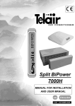
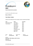
AIR CONDITIONER
GB
INSTALLATION AND USER MANUAL
VERS. 001
GB
Via E. Majorana , 49 48022 Lugo (RA) ITALY
“CE” COMPLIANCE STATEMENT
Under Machine Directive 89/392/EEC, attachment II A
We hereby represent that the air conditioner, the data concerning which appear
below, has been designed and built to correspond to the essential safety and
health requirements laid down by the European Directive on Machine Safety.
This statement shall not be valid any longer if any changes are made on the
machine without our written approval.
Machine: AIR CONDITIONER
Model:
ICEBERG …………………
Serial number: ………………………...
Directive of reference:
Machine Directive (89/392/EEC) in version 91/31/EEC
Low Voltage Directive (73/23/EEC)
Electro-magnetic Compatibility (89/336/EEC) in version 93/31/EEC
Harmonised standards applied, especially: EN 292-1; EN 292-2; EN 60204-1
DATE …03/01/2000…….
THE PRESIDENT
-2-
GB
CONTENTS
1 FOREWORD .................................................................................................................... pag. 4
1.1 Purpose and scope of this manual ............................................................................ pag. 4
1.2 Symbols and Definitions ............................................................................................ pag. 4
1.3 General Information ........................................................................................... pag. 4
2 AIR CONDITIONER IDENTIFICATION DATA ................................................................. pag. 5
2.1 Components ............................................................................................................... pag. 5
2.2 Identification plate ........................................................................................................ pag. 5
2.3 Technical features ....................................................................................................... pag. 5
3 SHIPPING, HANDLING, STORAGE ................................................................................. pag. 6
3.1 Storage ........................................................................................................................ pag. 6
3.2 Weight ......................................................................................................................... pag. 6
3.3 Handling ...................................................................................................................... pag. 6
4 INSTALLATION ................................................................................................................. pag. 6
4.1 Preliminary information ............................................................................................... pag. 6
4.2 Installation ................................................................................................................... pag. 6
4.2.1 Using the ventilation portholes .................................................................................... pag. 7
4.2.2 Opening a new hole .................................................................................................... pag. 7
4.2.3 Power supply cable ..................................................................................................... pag. 8
4.3 Positioning the air conditioner ..................................................................................... pag. 9
4.4 Installing the diffuser ................................................................................................. pag. 10
5 USER INSTRUCTIONS .................................................................................................. pag. 11
5.1 Foreword ................................................................................................................... pag. 11
5.2 Preliminary checks ................................................................................................... pag. 11
5.3 Air diffusion outlets .................................................................................................... pag. 11
5.4 Control panel ............................................................................................................. pag. 11
5.5 Turning on ................................................................................................................. pag. 11
5.6 Ventilation .................................................................................................................. pag. 12
5.7 Heating ...................................................................................................................... pag. 12
5.8 Turning off ................................................................................................................. pag. 13
5.9 Safety rules ............................................................................................................... pag. 13
5.10 Some problems and how to solve them ................................................................... pag. 13
6 MAINTENANCE .............................................................................................................. pag. 14
7 DISPOSAL ....................................................................................................................... pag. 14
8 TROUBLESHOOTING ................................................................................................... pag. 15
WIRING DIAGRAM ............................................................................................................ pag. 18
EXPLODED VIEW ............................................................................................................. pag. 19
SPARE PART LIST ........................................................................................................... pag. 21
GENERAL TERMS OF WARRANTY ................................................................................ pag. 23
-3-
GB
1
FOREWORD
1.2 Symbols and Definitions
This means that you must pay at-
MANUAL Refer carefully to this manual
before performing any operation on the air conditioner.
1.1 Purpose and scope of this manual
This manual has been drawn up by the Manufacturer in order to provide basic information and instructions for performing every operation for servicing and using the air conditioner in a proper and
safe manner.
It is an integral part of the conditioner equipment
should be kept clean and safe throughout its
working life.
It must follow the conditioner if the latter is installed
on a new vehicle, or if its ownership changes hands.
The information in this manual is addressed to the
personnel which must install the air conditioner, and
to all those involved in its maintenance and use.
This manual sets out the purpose the machine was
designed for, and contains all the information required to guarantee that it is used in a safe and
proper fashion.
Constant attention to the instructions laid down here
will guarantee the safety of the user, economy and
longer life of the machine.
To facilitate reference, this manual has been subdivided into chapters which specify the main notions; for quick consultation, refer to the table of
contents.
The most important parts of the text are in bold
letters and preceded by symbols described below.
Please read the contents of this manual carefully.
This is the only way to ensure that the air conditioner will work properly through time and be reliable, while safeguarding people and things.
Note: The information contained in this publication
was correct at the time it went to print, but may be
modified without advance notice.
-4-
tention to avoid serious consequences which might
lead to the death of the operators or at least to possible damage to their health.
This means a situation which
could take place during the lifetime of a product,
system or installation, and which is considered to
be hazardous in terms of damage to people, property, the environment or financial loss.
This means you must pay attention in order not to incur serious consequences
which might lead to damage to material goods, such
as resources or the product itself.
Especially important instructions.
The drawings are only provided by way of example.
Even though the machine you actually have may
differ from the illustrations contained in this manual,
safety and information about the same are guaranteed.
The manufacturer, as part of his policy of constant
development and updating, may effect changes
without providing advance notice.
1.3 General Information
The ICEBERG 3500 air conditioners have been
designed for installation on the roofs of vehicles.
They run on 230 VAC 50 Hz alternate current power
supply.
The power supply must never
fall below 210 VAC, and the frequency must stay
steadily at 50 Hz.
The use of air conditioners at a different voltage
from the above would compromise their good performance and could also be dangerous for the integrity of the equipment.
GB
2.2 Identification label
2. AIR CONDITIONER IDENTIFICATION DATA
2.1 Components (fig. 1)
1
2
3
4
5
6
7
8
9
10
Ventilation grid
Top hood
Identification label
Diffuser
Adjustable air outlets
Ambient air suction grid
Fan speed selector switch
Hot-cold air selector switch
Thermostat control
ON/OFF switch
1
2
3
4
5
6
Model
Machine code
Serial number
Compressor and fans consumption
Heater power
Coolant gas type and quantity
1
2
ICEBERG3500R
3
CODE : 00640
S.N.000303266
Refrigerating yeld : ............... 1,0 KW
Voltage : ..............................230 V a.c.
Frequency : ................................ 50 Hz
Inlet Power : (cooling) ........... 530 W
Air hater : ................................ 1000 W
Gas ................................. g.370 R134C
Weight : ...................................... 34 Kg
4
5
6
1
2
8
0
1
5 5 6 4
0 0 6 0 4 0 7
2.3 Technical features
ICEBERG
3
3.500
8
7
9
4
6
10
5
Cooling power
Fan speed number
Power supply
Consumption
Start up current
Absorbed power
Coolant gas
Generator requested
Air circulation
Heating power
Diffuser height
Dimensions (HxLxW)
Weight
3500 BTU
3.500R
3500 BTU
3
3
230 V 50 Hz
230 V 50 Hz
2,4 A
2,4 A
15 A (0,15 sec.)
15 A (0,15 sec.)
530 W
530 W
R 134 C
R 134 C
1500 W
3
240 m /h
-
1500 W
240 m3/h
1000 W
5.5 cm
5.5 cm
24x101x62cm
24x101x62cm
34 Kg
34 Kg
1
-5-
GB
3 SHIPPING, HANDLING, STORAGE
3.1 Storage
4
INSTALLATION
4.1 Preliminary information
The air conditioner is protected during shipping by
suitable packaging. The air conditioner must be
stored horizontally, in a covered, dry and ventilated
area.
The packaging is designed so as to allow stacking
of a maximum of 5 (five) air conditioners.
Do not turn the unit upside
down. The right position is the one shown by
the symbol printed on the package ( ) .
Stacking more than 5 air conditioners will not only compromise the integrity of the equipment, but will also be a risk to
personel.
Before installing the air conditioner, it is essential to read these instructions,
in order to avoid errors during installation
Improper installation of the air
conditioners can cause irreparable damage to
the equipment and compromise the safety of
the installation engineer.
Should the air conditioners be installed in a manner which does not comply with the instructions in
this manual, the Manufacturer shall be held blames
for malfunctions or for the safety of the air conditioner, under D.M. 89/392/EEC. Furthermore, he
shall be held blameless for any damage or injury to
persons
or things.
3.2 Weight
Weight without packing.
ICEBERG 3500
Kg 34
Installation must be performed
by qualified and properly trained personnel
only.
4.2 Installation
3.3 Handling
The air conditioners, complete with their packaging, can be moved using common lifting and transport vehicles.
The boxes are provided with spacers in order to
allow for the introduction of transpallet forks.
Before starting to install, you
must disconnect all the power supply of the
vehicle
Positive battery pole
Generator set (if present)
Outside power source.
During lifting and transport,
comply with accident prevention and safety
regulations. Use lifting and transport equipment
with a capacity greater than the load to be lifted.
Lack of compliance with these
instructions implies a risk of electrical shock.
Before going onto the roof of
the vehicle, you must make sure that it has been
designed to be walked on. Check with the person who equipped the vehicle. Otherwise, you
will have to prepare suitable scaffolding.
-6-
GB
In order to install the air conditioner, you must first
make sure the roof of the vehicle is able to hold its
weight. If not, reinforce it. Choose a central, level
and flat area on the roof. Make sure that no obstacle
inside the vehicle can hinder fastening of the diffuser
[Fig.1 ref. 4] and the exit of the cooled air from the
adjustable outlets [Fig. 1 ref. 5].
Remove existing rooflight and sealants making sure
roof surface is clean and even [Fig. 3 ref. 1] Seal
any screw holes and or cable entrance holes so
that no water can penetrate the roof space, using a
suitable sealent [Fig. 3 ref. 2].
To install the air conditioners, you can choose either of two solutions:
silicone, lining - must not be disposed of in the
open, but in special containers and delivered
to a Waste Collection and Disposal Centre.
All the waste material - glue,
Remuve existing rooflight and use aperture
Cut new aperture.
4.2.1 Using rooflight aperture
You can do so on condition that the aperture of the
rooflight measure of 400 x 400 mm. For the
dimensions of the air conditioners and of the holes
required to install them, refer to figure 2.
1
180
2
240
3
4.2.2 Opening a new hole
400
400
395
395
Choose a flat level position on the vehicle roof
beteween the support structure. Mark the aperture
400 x 400 mm square [Fig. 4 ref. 1].
Carefully cut out the opening on the roof, making
sure that no damage will be caused e.g. cables,
hoses, furniture, fittings. [Fig. 4 ref. 2].
615
615
1010
1010
Wear safety goggles and
gloves before using any power tools or handsaws.
400
620
Make a reinforcing frame along the perimeter of
the opening. Make a hole on one side in order to
lead the power supply cable through [Fig. 5].
2
-7-
GB
1
4.2.3 Power supply cable
To set up the power supply for the air conditioner,
lay a three-pole (positive-neutral-earth), power supply cable with a cross section of at least 2.5 mm2.
This cable must be connected at one end to the
differential cut-off switch previously placed inside
the distribution board of the vehicle, while the other
end must reach the opening on the roof. Let the
cable come out from the reinforcing frame by about
50 cm to allow easier connection to the air conditioner [Fig. 6].
1
6
4
Before performing any kind of
connection, always make sure that there is no
power inside the distribution board or at the
cable end.
The air conditioner must be powered from a separate cable, which must be provided with a 10A fuse.
The cable must be sheathed so
it can provide proper insulation under any condition of use of the vehicle.
5
-8-
GB
4.3 Positioning the air conditioner
Before positioning the air conditioner on the roof of
the vehicle, spread a sufficient of quantity slowdrying sealant around the edges of the opening.
Take the air conditioner on to the roof of the vehicle [Fig. 7 ref. 2] and position it over the opening
(previously treated with sealant). Remember that
the side with the ventilation grid must face the rear
end of the vehicle. The arrow on Figure 7 shows
the driving direction of the vehicle.
Do not crush the foam sealing
too much - it must be at least 10 mm thick
[Fig. 9 ref. 3].
If the lining is crushed too much, this will damage the support of the air conditioner and will
compromise the watertightness of the junction.
The support gasket must be
placed flush with the edge of the hole drilled,
on the back of the air-conditioning unit [fig. 7
ref. 1].
7
8
From within the vehicle, move the air-conditioning
unit until the gasket is flush with the rear section
of the roof opening.
The air ducts may be extended,
[fig. 8], they may therefore be used with roof
thickness 30 to 80 mm. Should the roof be
thicker, longer air ducts are available.
Fix the anchor frame to the air conditioner [Fig. 9
ref. 1] , as shown on Figure 9, using the four relevant screws [Fig. 9 ref. 2] without tightening them
all the way.
9
-9-
GB
4.4 Installing the diffuser
1
After securing the air conditioner to the roof of the
vehicle, connect the power supply cable to the connection terminal board [Fig. 10 ref. 3], located on
the diffuser, complying with the positions shown on
the adhesive label:
blue wire: neutral
brown wire: positive
yellow-green wire: earthing (
)
Fit the multi-pole cable connector [Fig. 10 ref. 2]
coming from the diffuser into the connector of the
conditioner [Fig. 10 ref. 1]. Fit both connectors,
11
1
2
12
Extend the air ducts [fig. 13 ref. 1] by 1 cm beyond the roof thickness and fit them between the
diffuser [fig. 13 ref. 2] and the air conditioner openings [fig. 13 ref. 3], Fasten the diffuser to the frame,
using the relevant four screws [fig. 13 ref. 4]. Fit
the air ducts[fig. 13 ref. 1] between the diffuser
[fig. 13 ref. 2] and the linings [fig. 13 ref. 6].
10
pressing until they are firmly fastened.
Before fastening the diffuser to
the ceiling of the vehicle, make sure that no
cable is in contact with the resistances of the
fan speed selector switch [Fig. 11 ref. 1], because
- when the air conditioner is running - these become very hot and can cause a serious hazard
for the insulation of the power cables.
Make sure that both resistances of the fan speed
selector switch are not in contact with each
other [Fig, 12 ref. 1] but are clearly separated
[Fig. 12 ref. 2].
Make sure that the power supply cable is not
too long, to avoid jamming the air intake holes
[Fig. 1 ref. 6].
- 10 -
13
GB
5. USER INSTRUCTIONS
5.1 Foreword
The Manufacturer shall not be
held liable for any damage due to the air conditioner not working.
The air conditioner consists of a compressor running at 230 VAC 50 Hz. The compressor compresses the coolant gas inside a coil pipe which,
when ventilated, gives off the heat developed during compression. The coolant gas is then conveyed
into a condenser where it can expand and thus
absorb heat from the air going through the condenser.
The cooled air is spread through the inside of the
vehicle by a fan which works at an adjustable speed.
A thermostat adjusts the air temperature.
ICEBERG can provide cold air in summer and hot
air in winter.
When your vehicle has been exposed for a long
time to sunlight, it is good practice, before starting
up the air conditioner, to open the doors and windows in order to let out the heat which has built up
inside.
When the indoor temperature becomes the same
as the outdoor temperature, close all the doors
and windows again and start up the air conditioner.
Do not open doors or windows wen the conditioner
is running except in case of need.
To obtain better performance, we suggest you aim
one of the outlets towards the door so that hot air
does not come in when you open it.
5.2 Preliminary checks
Before turning the air conditioner on, you must perform a few simple operations.
Make sure that the condensate drainage system
is not clogged [Fig. 13 ref. 5].
Make sure that the power supply voltage and frequency are those listed in the previous paragraph.
Make sure that nothing is preventing the air from
circulating freely inside the ventilation conduits and
outlets. The outside ventilation grids must always
be free for the air conditioner to be truly efficient.
5.3 Air diffusion outlets
The diffuser panel [Fig. 1 ref. 4] houses five cooled
or heated air diffusion outlets [Fig. 1 ref. 5].
Each outlet is provided with two mobile baffle plates
which allow you to choke and direct the air jet [Fig.
14]. Press on the baffle plates to choke the air jet
until you close it completely off. Turn the baffle
plates to point the air jet in any direction.
14
5.4 Control panel (Fig. 15)
Fan speed selector switch [Fig. 15 ref. 1].
Ventilation / cooling selector switch with thermostat [Fig. 15 ref. 2].
Cold/hot air selector switch [Fig. 15 ref. 3].
ON/OFF switch [Fig. 15 ref. 4].
5.5 Turning on
The air conditioner is provided
with an environmental thermostat, with a
minimum working temperature of 18°C (+/-1°C).
Below this temperature, the thermostat does not
enable operation of the compressor. This
prevents the risk of ice developing inside the
air conditioner. The fans and heating function
are still enabled.
To turn the air conditioner on, set the ON/OFF
switch [Fig. 15 ref. 4] to the ON position. Position
the cold/hot air selector switch [Fig. 15 ref. 3] on
the symbols
and then turn the thermostat [Fig. 15 ref. 2] clockwise, positioning it on
the temperature value you want.
The thermostat keeps the temperature you have
chosen constant, and does so automatically, turning the air conditioner compressor on and off.
The temperature scale is marked by a series of dots
of different sizes.
- 11 -
GB
First choose Maximum Cool and the second ventilation speed.
When you have reached the temperature you
want, choose the first ventilation speed, then turn
the thermostat knob counter-clockwise until the
compressor goes off (you can tell this has happened
when the noise diminishes).
Now select the second ventilation speed again,
and the system will preserve the temperature you
have set.
1
2
4
3
5.6 Ventilation
If you want to move the air inside the vehicle without heating or cooling, proceed as follows:
Press the Cold Air /Hot Air selector [Fig. 15 ref.
1
3] in the position
2
Position the Thermostat [Fig. 15 ref. 2] selector
in the position
Press the ON/OFF switch [Fig. 15 ref. 4] to position it
3
4
Choose the ventilation speed required [Fig. 15
ref. 1].
5.7 Heating
15
The minimum cooling value is marked by the smallest dot, the maximum cooling value is marked by
the largest [Fig. 15 ref. 2].
The thermostat controls the temperature automatically, but the speed of the fan must be set manually by the user.
Set the fan speed required on the relevant selector
switch [Fig. 15 ref. 1].
To use the air conditioner in the most effective
manner, we suggest the following settings:
The electrical heater of the air conditioner cannot
replace a conventional heating system, but it does
help to warm up the air in the morning or on cool
days.
Press the Cold Air /Hot Air selector in the position
Position the Thermostat [Fig. 15 ref. 2] selector in
the position
Press the ON/OFF switch [Fig. 15 ref. 4] to position
Minimum speed - Minimum cool (night-time)
Medium speed - Maximum cool
Maximum speed - Medium cool
To use the conditioner more efficiently, we suggest
you perform the following operations:
- 12 -
Choose the ventilation speed required [Fig. 15 ref.
1].
GB
5.8 Turning off
To turn the air conditioner off, position the switch
[Fig. 15 ref. 4] on the
position.
After having turned the air conditioner off, either using the thermostat knob
or the ON-OFF switch, wait at least three minutes before turning it back on again, so the coolant can stabilise its pressure. Lack of compliance with this rule may damage the compressor irreparably.
5.9 Safety rules
Always use earthed power sources protected by
differential switches.
Never use the air conditioner near flammable liquids.
Never use the air conditioner for any purpose other
than that designed for by the Manufacturer.
Never modify or tamper with any part of the air
conditioner.
Use only original spare parts.
Maintenance and repairs must be performed by
specialised personnel only.
Installation must only be performed by qualified
personnel.
Never allow animals or children near the equipment.
Never put your hands inside the ventilation grids.
Never put foreign objects into the ventilation outlets.
Should the air conditioner be subject to an impact, have it checked by specialised personnel before using it again.
In case of fire, never open the top lid of the air
conditioner, but use a standard non water based
fire extinguisher.
Do not use water to put the fire out.
5.10 Some problems and how to solve them
Unsatisfactory performance of the air conditioner
will usually be due to improper use rather than to
malfunction check.
The conditioner is not too small compared to the
volume of air it has to condition.
The walls of the vehicle are sufficiently insulated.
The doors are not opened too frequently.
There are not too many people inside the vehicle.
The voltage is less than 230 V.
Here is a list of possible problems and how to solve
them.
Before anything else, check if:
the power supply has dropped below 205 V;
the ventilation grids are jammed;
the air diffusion outlets are open.
1) The air conditioner will not start up:
Check whether the ON/OFF switch is in its ON
position [Fig. 15 ref. 4], the thermostat is in its allcold position [Fig. 15 ref. 2], the fan speed selector switch is in position 1 [Fig. 15 ref. 1].
Make sure then that the power source is live by
using a domestic appliance or a voltmeter.
2) The compressor does not work:
For the compressor to work, the thermostat [Fig.
15 ref. 2] must be in its cold position, the hot/cold
selector switch in cold position and at least the first
fan speed on.
3) The fans do not work:
Make sure that the ON/OFF switch [Fig. 15 ref.
4] is in its ON position and that the fan speed selector switch [Fig. 15 ref. 1] is set on value 1.
4) The condenser fan does not work:
Make sure that the condenser fan is not hindered
by foreign matter.
5)The heating resistance does not work:
Make sure that the hot/cold selector switch is in
hot position [Fig. 15 ref. 3].
6)The air conditioner performs poorly:
If the air conditioner performs poorly, you must
clean the air filter, the condenser and the evaporator using specific detergents. We suggest you clean
these before using the air conditioner when it has
not been used for a long time. If the air conditioner
still does not return to its original performance after
cleaning of the exchangers, you must have the
coolant gas level checked by a pecialist.
- 13 -
GB
6.
MAINTENANCE
7. DISPOSAL
Accurate inside cleaning of the air conditioner is
important to keep it efficient.
If you have to dispose of the air conditioner, refer
to a specialised workshop.
Before accessing the air con-
All the waste material must not
ditioner, you must disconnect the 230V power
supply and wait for all parts to cool off.
be disposed of in the open, but in special containers and delivered to a Waste Collection and
Disposal Centre.
Take off the outside cover and spray the proper
detergent on the heat exchangers (evaporator and
condenser), and then rinse to remove all debris.
Make sure that the drainage holes are free [fig.
13 ref. 5].
Make sure that the sealing lining is in good condition and that no water is leaking into the vehicle.
Any traces of rust must be removed, and metal
parts protected by repainting.
Make sure that the insulation of the electric cables
are whole and remove any trace of humidity.
Make sure that all the screws are firmly tightened.
When putting away in the garage for the winter,
you should protect the air conditioner from dust
using a special cover (accessory code 00639).
- 14 -
GB
8.
TROUBLESHOOTING (for technical staff only)
Before performing the checks listed below, make sure that the ON/OFF switch is in the
ON position [Fig. 15 ref. 4], the thermostat is in the all-cold position [Fig. 15 ref. 2], and the fan speed
selector switch is in position 1 [Fig. 15 ref. 1].
1) PROBLEM The air conditioner does not start up
CHECK
Make sure that the infeed terminal of the air conditioner between the blue and the yellow wire is
powered at 230 VAC [Fig. 16 ref. 4].
OPERATION Check the differential switch, the fuse protection on the power supply line, the wholeness of the
power supply line.
CHECK
Make sure that there is 230 VAC power between the blue and the brown wire of the voltage transformer [Fig. 16 ref. 15].
OPERATION Check the wholeness of the ON/OFF switch and its connections, and replace or reconnect if necessary [Fig. 15 ref. 1].
CHECK
Make sure that there is 12 VAC power between the pink and the yellow wire of the transformer
[Fig.18 ref. 15].
OPERATION If there is no voltage, replace the transformer.
CHECK
Make sure that there is 12 VAC power between the pink and the violet wire of the transformer.
OPERATION If there is no voltage, replace the transformer.
CHECK
Disconnect both blue wires from the DC feeder board, and check whether there is continuity between both ends [Fig. 16 ref. 14].
OPERATION If there is no continuity, replace the inductor [Fig. 16 ref. 13].
CHECK
Make sure that there is 12 VDC between the red and the black wire of the DC feeder board
[Fig. 16 ref. 14].
OPERATION If there is no voltage, replace the feeder board.
CHECK
Make sure that there is 12 VDC between the black wire of the relay [Fig. 16 ref. 2] and the red wire
of the fan speed selector [Fig. 16 ref. 8].
OPERATION Check the harness and the multi-wire connector [Fig. 16 ref. 7].
CHECK
Make sure that there is 12 VDC on the fan speed selector [Fig. 16 ref. 8] between the orange and
the black wire of the relay.
OPERATION Replace fan speed selector.
CHECK
Make sure there is 230 VAC between the white wire of the relay [Fig. 16 ref. 2] and the blue wire
of the feeder input terminal [Fig. 16 ref. 4].
OPERATION Replace the relay.
CHECK
Make sure that when the hot/cold selector switch [Fig. 16 ref. 3] is positioned on cold, there is 230
VAC between the pink and the blue wire of the infeed terminal [Fig. 16 ref. 4].
OPERATION Replace the hot/cold selector switch.
CHECK
Make sure that when the hot/cold selector switch [Fig. 16 ref. 3] is positioned on hot, there is 230
VAC between the grey and the blue wire of the infeed terminal [Fig. 16 ref. 4].
OPERATION Replace the hot/cold selector switch.
CHECK
Make sure that there is 230 VAC between the violet wire of the thermostat [Fig. 16 ref. 5] and the
blue wire of the infeed terminal [Fig. 16 ref. 4] (when the ambient temperature is below 16°C, the
thermostat will not close its contacts, so this test must be performed at an ambient temperature over
20°C).
OPERATION Replace the thermostat
CHECK
Make sure that when the hot/cold selector [Fig. 16 ref. 3] is in cold position, and after the plastic side
cover has been removed, the following are on the compressor [Fig. 16 ref. 11]: voltage at 230 VAC
between the blue and the white wire; voltage at 230 VAC between the black and the white wire;
voltage at about 250 VAC between the orange and the white wire.
OPERATION Check the connector and the harness. Replace the temperature switch on the compressor.Replace
the condenser [Fig. 16 ref. 10].
CHECK
Make sure that there are 12 VDC between the green speed selector switch wire [Fig. 16 ref. 8] and
the black relay selector wire [Fig. 16 ref. 2].
OPERATION Check the harness and the multi-wire connector.
- 15 -
GB
2) PROBLEM The compressor does not work
CHECK
Make sure that there is 12 VDC between the black wire of the relay [Fig. 16 ref. 2] and the red
wire of the fan speed selector [Fig. 16 ref. 8].
OPERATION Check the harness and the multi-wire connector [Fig. 16 ref. 7].
CHECK
Make sure that there is 12 VDC on the fan speed selector [Fig. 16 ref. 8] between the orange and
the black wire of the relay.
OPERATION Replace fan speed selector.
CHECK
Make sure there is 230 VAC between the white wire of the relay [Fig. 16 ref. 2] and the blue wire
of the feeder input terminal [Fig. 16 ref. 4].
OPERATION Replace the relay.
CHECK
Make sure that when the hot/cold selector switch [Fig. 16 ref. 3] is positioned on cold, there is
230 VAC between the pink and the blue wire of the infeed terminal [Fig. 16 ref. 4].
OPERATION Replace the hot/cold selector switch.
CHECK
Make sure that there is 230 VAC between the violet wire of the thermostat [Fig. 16 ref. 5] and the
blue wire of the infeed terminal [Fig. 16 ref. 4] (when the ambient temperature is below 16(C, the
thermostat will not close its contacts, so this test must be performed at an ambient temperature
over 20(C).
OPERATION Replace the thermostat
CHECK
Make sure that when the hot/cold selector [Fig. 16 ref. 3] is in cold position, and after the plastic
side cover has been removed, the following are on the compressor [Fig. 16 ref. 11]: voltage at
230 VAC between the blue and the white wire; voltage at 230 VAC between the black and the
white wire; voltage at about 250 VAC between the orange and the white wire.
OPERATION Check the connector and the harness.
Replace the temperature switch on the compressor.
Replace the condenser [Fig. 16 ref. 10].
3)
CHECK
OPERATION
CHECK
OPERATION
CHECK
OPERATION
CHECK
OPERATION
CHECK
OPERATION
PROBLEM The fans do not work
Make sure that there is 12 VDC between the black wire of the relay [Fig. 16 ref. 2] and the red
wire of the fan speed selector [Fig. 16 ref. 8].
Check the harness and the multi-wire connector [Fig. 16 ref. 7].
Make sure that there are 12 VDC between the green speed selector switch wire [Fig. 16 ref. 8]
and the black relay selector wire [Fig. 16 ref. 2].
Replace the fan speed selector switch.
Make sure that there is 12 VDC between the black and the green wire of the evaporator ventilator
[Fig. 16 ref. 9].
Check the harness and the multi-wire connector.
With the hot/cold selector [Fig. 16 ref. 3] on cold position, make sure there are 12 VDC between
both brown wires and the red wire of the ventilation speed selector [Fig. 16 ref. 8].
Make sure that the contacts 2 and 3 of the hot/cold selector switch are closed, and replace them if
necessary.
Make sure that there are 12 VDC between the black and the red wire of the condenser [Fig. 16
ref. 12].
Check the harness and the multi-wire connector.
4) PROBLEM The fan of the condenser does not work
CHECK
With the hot/cold selector [Fig. 16 ref. 3] on cold position, make sure there is 12 VDC between
both brown wires and the red wire of the ventilation speed selector [Fig. 16 ref. 8].
OPERATION Make sure that the contacts 2 and 3 of the hot/cold selector switch are closed, and replace them if
necessary.
CHECK
Make sure that there is 12 VDC between the black and the red wire of the condenser [Fig. 16 ref. 12].
OPERATION Check the harness and the multi-wire connector.
- 16 -
GB
5) PROBLEM The fan of the evaporator does not work
CHECK
Make sure that there is 12 VDC between the green ventilation speed selector switch wire [Fig. 16
ref. 8] and the black relay selector wire [Fig. 16 ref. 2].
OPERATION
CHECK
OPERATION
Replace the fan speed selector switch.
Make sure that there is 12 VDC between the black and the green wire of the evaporator ventilator
[Fig. 16 ref. 9].
Check the harness and the multi-wire connector.
6) PROBLEM The heating resistance does not work
CHECK
OPERATION
CHECK
OPERATION
Make sure that there is 12 VDC on the fan speed selector [Fig. 16 ref. 8] between the orange and
the black wire of the relay.
Replace fan speed selector.
Make sure there is 230 VAC between the white wire of the relay [Fig. 16 ref. 2] and the blue wire of
the feeder input terminal [Fig. 16 ref. 4].
Replace the relay.
7) The air conditioner is performing poorly
CHECK
Check the cleanliness of the air filter and exchangers.
OPERATION If the air conditioner is clean, then you must check the coolant gas tcover.
Proceed as follows: open the high pressure valve [Fig. 17 ref. 17], unscrewing the safety cap. Use
a sharp instrument to press on the inside of the high pressure valve, thus allowing all the coolant
gas to come out.
Connect the vacuum pump to the high pressure valve and let it run for at least one hour.
Quickly disconnect the vacuum pump and connect the refill station to the high pressure valve
immediately, and put in 370 g of R134C gas.
When you have finished filling, close the high pressure valve with its safety cap.
- 17 -
1
2
3
4
5
6
7
8
- 18 -
DIFFUSER
ON/OFF switch
Relay
Cold/hot selector switch
Feeding connection terminal
Thermostat
Fan speed selector switch
Connector
Resistance
9
10
11
12
13
14
15
CONDITIONER
Evaporator electric fan
Compressor
Condenser electric fan
Inductor
12VDC feeder
230/12 transformer
Armored resistor 1.5 omh/ 50W
ICEBERG 3500 WIRING DIAGRAM
GB
16
GB
17
- 19 -
GB
18
- 20 -
GB
- 21 -
GB
NOTES
- 22 -
GB
GENERAL TERMS OF WARRANTY
Telair guarantees that its products are without faults or defects in their
material and/or construction.
The effects of the warranty are understood to be limited to the right to
obtain replacement or repair free of cost of any part which should turn out
to be defective, within 12 months from the date of purchase of the product
and in Telair’s opinion.
It is understood that the purchaser has no right whatsoever:
to terminate the contract;
to claim damages for people or things;
to demand an extension of the warranty in case of any product defect
or malfunction.
Any transport charges are on the account of the purchaser, as well as any
expenses for on-site checks requested by the purchaser and accepted by
Telair.
The warranty shall be valid only if the customer is able to show a document
evidencing the date of purchase (invoice or receipt).
This document must be kept whole and must be submitted to the Telair
after-sales centre when asking for operation under warranty.
- 23 -
Foto e disegni non contrattuali - Les photos et les dessins ne sont donnés qu’à titre indicatif.
We reserve the right to make technical changes without prior notice - Fotos und Zeichnungen
nicht vertraglich. Fotos y planos no indicados en contrato
IN EUROPE:
EUROPE:
IN
GREAT BRITAIN - SCAN TERIEUR LTD
AIR CONDITIONER
ITALY
Via E.Majorana 49
48022 LUGO( RA )
Tel. + 39 0545 25037
Fax.+ 39 0545 32064
Tel. Servizio Assistenza
899 899 856
E-mail: [email protected]
www.telecogroup.com
GREAT BRITAIN - SCAN TERIEUR LTD
30,The
TheMetro
Metro
Centre,
Tolpits
- Watford,
30,
Centre,
Tolpits
LaneLane
Herts - England - WD18 9XG
Watford,
Tel. 01923
800353
- Fax
Herts
- England
- WD18
9XG01923 220358
Tel. 01923 800353 - Fax 01923 220358
HOLLAND - KARMAN AGENTUREN
Emmastraat,
31
HOLLAND
- KARMAN
AGENTUREN
Emmastraat,
31
1213 AJ Hilversum
- Holland
1213
AJ Hilversum
Tel. 035
6240156- -Holland
Fax 035 6242141
Tel.
035 [email protected]
6240156 - Fax 035 6242141
e-mail:
FRANCE
FRANCE- GERARD
– BLEYSDURAND
ANTOINE – BLEYS JEAN-PHILIPPE
Lieu
dit Borde
19, Rue
de laRouge
Parcheminerie
31590 Verfeil - France
18700 Aubigny sur Nere - France
Tel. 05 61356238 - Fax. 05 61743502
Tel. 02 48580367- Fax. 02 48583585
[email protected]
Mobil. 06 78262186 Mobil. 06 07012634
e-mail: [email protected]
ESPAÑA
- NAUCCA ACCESORIOS Y- [email protected]
REPUESTOS
ESPAÑA
- NAUCCA
CARAVANING, S.A.
Calle
Pallars,
141 - 143 4°B
Poligono
Industrial
CAN ROQUETA 2 – Calle Can Lletget,2
08018
Barcelona
España
Tel.
093Sabadell
3099537 -(Barcelona)
Fax. 093 4850700
08202
- España
e-mail:
[email protected]
Tel. 0937
457 054 - Fax. 0937 254 484
e-mail: [email protected]
ÖSTERREICH - TELECO GmbH
82041
Deisenhofen
ÖSTERREICH
– TELECO
GmbH
Tel.
08031
98939 - Fax.- 08031 98949
82041
Deisenhofen
e-mail: [email protected]
Tel. +49 08031 98939 - Fax. +49 08031 98949
www.telecogroup.com
e-mail: [email protected]
www.telecogroup.com
IN
DEUTSCHLAND
IN DEUTSHLAND
TELECO
GmbH
82041 Deisenhofen - Tel. 08031 98939 TELECO GmbH
Fax. 08031 98949
82041
Deisenhofen
Mit
unserer
Servicenummer
sind Sie
Tel. 08031
98939 - Fax. 08031 98949
01805
006 857
e-mail:mit
[email protected]
direkt
dem Teleco-Vertreter
in
Ihrer Nähe verbunden.
www.telecogroup.com
Händler und Info in Ihrer Nähe:
01805 006857
Service für Teleco Anlagen in Deutschland:
09001000690
KUNDENDIENST
BEI
AUSGEWÄHLTEN
BOSCH SERVICE!