1
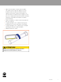
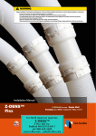
BK-CG-101 • 891152
WARNING
Improper installation of Vent System and Components, or failure to follow installation instructions, can result in property damage or serious injury.
-
Examine all components for possible shipping damage prior to installation;
Proper joint construction is essential for a safe installation. Follow these instructions exactly as written;
This venting system must be free to expand and contract. This venting system must be supported in accordance with these instructions;
Check for proper joint when joining pipe to fittings;
Check for unrestricted vent movement through, walls, ceilings, and roof penetrations;
Different manufacturers have different joint systems and adhesives. Do not mix pipe, fittings or joining methods from different manufacturers
Installation Manual
Z-DENS™
Single Wall
Single Wall Venting
ULC-S636 / Class IIC- Max.110°C
Installation Manual CoxDENS® PPs
CONTENTS
Introduction
3
Installation Requirements
3
Approvals/Codes
3
Product specifications
3
CoxDENS PPs Components
®
General installation conditions
4
4
Vent Support Spacing
5
Pitch
5
Installation of the CoxDENS PPs system
6
Dealing with Condensate
8
Termination
9
®
Vertical Termination
Vertical Termination through a masonry Chimney
9
10
Horizontal Termination
11
Maintenance
12
2
10-1-2013
INTRODUCTION
Product specifications
•
Single wall CoxDENS® PPs is third party certified to ULC-S636
Vent pipes made of flame retardant Polypropylene material
(certified for use flue gas in accordance with a European
standard for Class IIC rating (exhaust temperatures up to 110°C
standard DIN EN14471);
(230°F) and CE EN14471. Certified diameters are 60mm (2”),
•
Sealings are made of EPDM;
80mm (3”), 110mm (4”), 125mm (5”), 160mm (6”) and 200mm (8”).
•
Supports of aluminium;
The following installation instructions are in accordance with the
•
Supports of galvanized steel;
requirements of section 4 of the ULC-S636 Standard.
•
Cox Geelen Pipe lubricant Chloride free;
•
System diameters:
Single wall CoxDENS® PPs is a vent system for type BH Gas-
- Residential: 60mm (2”), 80mm (3”), 110mm (4”);
Venting, for use with ANSI Category II and IV gas burning
appliances (condensing boilers) with a max flue gas temperature
- Commercial: 125mm (5”), 160mm (6”), 200mm(8”);
•
of 110°C.
Shaftcover:
- Cover house is made from HDPE in the colour RAL9005
(Black), sizes 60mm (2”), 80mm (3”), 110mm (4”);
In addition, please refer to the appliance manufacturer’s
- Cover house is made from Stainless steel and aluminium
instructions for restrictions to the total vent length or height,
in the colour RAL9005 (Black), sizes 125mm (5”), 160mm
number of elbows that can be used, sizing of the vent or specifics
(6”), 200mm(8”);
as to appliance connections before proceeding with the installation
- Termination pipe is made from UV-stabilized
of this product. Appliance manufacturer’s installation instructions
Polypropylene material;
take precedence over this document.
- Gasket is made of EPDM in the colour RAL9005 (Black);
- Bird mesh made of stainless steel;
•
Concentric Roof termination:
INSTALLATION REQUIREMENTS
- Internal vent pipe of flame retardant Polypropylene
Installation and Annual servicing of the CoxDENS® PPs vent system
- External air pipe of galvanised steel sheet material in
must be performed by a qualified installer, service contractor or gas
the colour RAL9016, sizes Ø60/100mm (Ø2”/4”) and
supplier. The safe operation of a system is based on the use of parts
Ø80/125mm (Ø3”/5”);
material;
supplied by the manufacturer and the performance of the system
- External air pipe is made of galvanised steel sheet
may be affected if the combination of these parts is not used in the
material in the colour RAL9005, only size Ø110/160mm
actual building construction.
(Ø4”/6”);
Acceptance of the system is dependent upon full compliance with
- Termination cap is made of UV-stabilized Polypropylene
the installation instructions.
material in the colour RAL9005, only Ø60/100mm
(Ø2”/4”) and Ø80/125mm (Ø3”/5”);
- Roof flashing is made of non-lead butyl flashing with
Polyethylene swivels;
Approvals/Codes
- Roofflashing for flat roof is made of aluminium;
The installation has to conform to all relevant local, State, Provincial
•
or National codes. Single wall CoxDENS® PPs venting system is
Single Wall Roof termination:
- Internal vent pipe of flame retardant Polypropylene
approved for use under ULC-S636 Class II-C gas-fired appliances
material;
with a maximum flue gas temperature of 110°C (230°F). Cox Geelen
- External pipe is made of galvanised steel sheet material in
guarantees Single wall CoxDENS® PPs up to a maximum flue gas
the colour RAL9005, only size 125mm (5”), 160mm (6”),
temperature of 120°C (248°F).
200mm(8”);
•
All penetrations of fire rated walls, floors, and ceilings must comply
with national and local building codes and regulations, and be
approved by the local regulatory authority and/or building inspectors.
Concentric Wall termination:
- Internal vent pipe of flame retardant Polypropylene
material;
- External air pipe of galvanised steel sheet material in
the colour RAL9016, sizes Ø60/100mm (Ø2”/4”) and
Ø80/125mm (Ø3”/5”);
10-1-2013
3
- Nozzle is made of Polypropylene in the colour RAL7001,
sizes Ø60/100mm (Ø2”/4”) and Ø80/125mm (Ø3”/5”);
- External air pipe of galvanised steel sheet material
5. CoxDENS® PPs system expand and contract slightly
during heating cycles. This vent system has to be
supported in accordance with these instructions.
without separate nozzle in the colour RAL9016, only size
Ø110/160mm (Ø4”/6”);
6. Appliances can be operated immediately upon the
- Internal wall plate is made of Galvanised steel and
aluminium in the colour RAL 9016;
completion of the CoxDENS® PPs Vent System
installation.
- Outside EPDM Wall plate is in the colour RAL7001 (grey);
•
7. The vent pipe of CoxDENS® PPs is rated to a maximum of
Plume Management Kit:
- Termination pipes are made from UV-stabilized
5000Pa (0.725psi) or 20” of water column.
Polypropylene material, only for vent system Ø60mm (2”),
8. The maximum flue gas temperature for CoxDENS® PPs is
Ø80mm (3”);
- Supports of PVC;
110°C (230°F) for ULC-S636 compliant installations. Cox
- Bird mesh made of stainless steel.
Geelen guarantees CoxDENS® PPs up to a maximum flue
gas temperature of 120°C (248°F).
COXDENS® PPS COMPONENTS
9. Cox Geelen Pipe lubricant (art.no. 0005CA000),
For a list of ULC-S636 approved CoxDENS PPs components,
please consult the CoxDENS® PPs catalogue at
www.coxgeelen.com.
®
especially made for the assembly of exhaust pipes in
plumbing and heating systems. May be applied to all
gaskets for ease of assembly. Don’t use another Pipe
lubricant.
10. Free standing components (i.e., above a roof) must not
General installation conditions
exceed a maximum vertical height of 1m (39”) (Wind
1. Do not install CoxDENS® PPs in areas where ambient air
temperature exceeds 150°C (302°F).
load). When the freestanding length is greater, the
flue liner has to be stabilized. The maximum distance
between the outer surface of the flue liner and the wall is
2. Do not store the CoxDENS PPs system in a corrosive
®
50mm (2”) (subjected to bracket strength).
environment, and keep protected from UV light (ideally in
it’s packaging).
11. The minimum clearance to combustibles materials is
zero, 0mm (0”).
3. The maximum continuous vertical vent length is unlimited,
the maximum distance between the supports is 2m (78”),
12. Unless approved by the appliance manufacturer, only
see figure 1. Always refer to the manufacturer’s instruction
one appliance may be attached to the vent system.
for appliance specific vent limitations.
13. Do not use CoxDENS® PPs with any other manufacturer’s
4. The horizontal installation length is unlimited, the
maximum distance of a non vertical installation between
components must be used exclusively throughout the
the supports is 1m (39”)*, see figure 2. The venting system
entire vent system.
has to be sloped upwards not less than 50mm (2”) per
1000mm (39”) from the appliance to the vent terminal,
see figure 3. Always refer to the manufacturer’s instruction
for appliance specific vent limitations.
*NOTE: To meet requirements of ULC-S636,
the maximum distance of a non vertical installation
between the brackets of the vent system 2” (Ø60mm) is
0,5m (19”).
4
vent components. Cox Geelen CoxDENS® PPs
10-1-2013
Installation Manual CoxDENS® PPs
Vent Support Spacing
—z› Typical horizontal support spacing
——› Overview
—x› Typical vertical support spacing
Pitch
—c› Typical horizontal situation
10-1-2013
5
Installation Manual CoxDENS® PPs
INSTALLATION OF THE COXDENS® PPS SYSTEM
•
Check the presence of the seals and their correct
q
placement; q
•
Installation: before putting the sections together, the push in
spigot and the black seals have to be rubbed with special
Chloride free Pipe Lubricant (only obtainable at Cox Geelen
BV), so that a smooth installation is possible;
•
A locking clamp is required at every vent joint. Slide the
locking clamp over the male-end of the pipe with the
hook facing the joint (Type wa for size 2”, 3”, 4” and Type
wb for size 5”, 6” and 8”);
Type A
Type B
wa
•
The installation of the separate sections will be connected
by pushing the male-end together with the female-end
wb
e
and snap the hook over the gasket bead to secure the
two vent parts together; e
ATTENTION: NEVER USE SCREWS OR ADHESIVES FOR
CONNECTIONS OF THIS SYSTEM. SYSTEM IS DESIGNED
FOR USE WITH CLAMPS AS STATED ABOVE ONLY!
•
The metal support can only be mounted on the body of
the vent pipe. Determine the location where the support
anchor bolt will mount into the wall or framing member.
Mount the anchor bolt into the wall at that location. Install
the body of the support onto the anchor bolt by rotating
the body of the support with the nut onto the threads
of the anchor bolt. Open the support bracket to wrap
around the body of the CoxDENS vent pipe. Secure the
®
support around the vent pipe by tightening the 2 bolts of
the support. r
6
10-1-2013
r
•
After locking the venting parts, the complete vent system
has to be fixed to the building construction with the
supports. For vertical installation the maximum distance
between the supports is 2m (78”) and for non-vertical
installation the maximum distance between the supports
is 1m (39”). The venting system has to be sloped upwards
not less than 50mm (2”) per 1000mm (39”) from the
appliance to the connection with the vent terminal.
•
Don’t install the system upside down in order to avoid
leakage of condensate.
•
Making a specific length: when a pipe section is too long,
it’s possible to shorten this (e.g. with a hacksaw).
•
Making a specific length: when a pipe section is too
short, it can be extended by use of an adjustable pipe.
•
Remove burrs at the pipe ends.
CAUTION
Damage to the gasket can result in the
dangerous release of carbon monoxide!
10-1-2013
7
DEALING WITH CONDENSATE
into the boiler room and equally to prevent back flow of fumes from
the sewer discharge point.
Always read the Appliance manufacturers installation instructions in
To avoid condensate freezing and disruption of normal operation
conjunction with those from Cox Geelen.
of the appliance the condensate evacuation pipe routing should be
If the appliance manufacturers installation instructions state that
suitably arranged internally wherever possible.
condensate cannot be discharged through the boiler appliance
Exposure of condensate collection and discharge pipe work to
then the flue gas condensate must not be allowed to flow back to
extreme temperatures and UV light should be avoided at all times.
the boiler. This can be achieved by fitting the condensate trap and
Condensate removal and disposal must conform to NEN 3287 and
drain component into the CoxDENS PPs flue system.
NEN 3215. All components within this condensate collection and
Regardless of boiler appliance flue system installation mode -
discharge system should be manufactured in condensate resistant
Vertically or Horizontally - the condensate trap and drain can be
materials- this can be assured by use of the Cox Geelen siphon and
fitted - see diagrams below. The condensate trap’s drain off pipe
drain pipe (part no 0004.CA.000).
must be connected to a condensate resistant tube of minimum
The condensate removal components, siphon and discharge pipe
internal diameter ¾”, then via a siphon/ airlock controlled outflow
work must be
to a secured “open” connection to the sewer drain or neutralising
qualified appliance service engineers ideally at the annual service
system. An appropriately sized siphon/airlock MUST be fitted to
of the appliance.
®
inspected and maintained annually by suitably
maintain room sealed conditions, preventing flue gas emissions
Vertical connection
Connection to drain
Horizontal connection
q Drain
w CoxDENS® PPs vent system
e Condensation drain
r Appliance
t Drainage - canal
8
10-1-2013
Installation Manual CoxDENS® PPs
TERMINATION
Typical sloping roof situation
Vertical Termination
•
If the position of the roof terminal is specified, make a
hole in the roof:
a) For terminal Ø60/100mm (Ø2”/4”) and Ø80/125mm
(Ø3”/5”) with a minimum of Ø130mm (Ø5,5”) depending
on the roof sloping;
b) For terminal Ø110/160mm (Ø4”/6”) with a minimum of
Ø170mm (Ø7”) depending on the roof sloping;
•
For a good water seal, install the correct roof flashing on
the roof;
•
Install the roof terminal vertically through the roof flashing
and fix them with the support to the inside of the roof;
•
The roof terminal is now ready to connect with the other
vent parts.
Typical flat roof situation
10-1-2013
9
Installation Manual CoxDENS® PPs
VERTICAL TERMINATION THROUGH A MASONRY CHIMNEY
•
CoxDENS® PPs expand slightly during normal operation.
CoxDENS® PPs pipe can expand upwards through the
When using a masonry chimney as a passageway for CoxDENS®
PPs, the chase must be structurally sound and free of any debris
Chimney Cover;
•
or obstructions;
•
Install a Base Support bracket just below the entry point
into the chase;
If only supported with a base support at the bottom
and a standard chimney cover at the top, the maximum
•
Measuring from the base support, attach spacers at
intervals of 78” (2m) or less to the rigid pipe.
continuous vertical vent length for a rigid CoxDENS® PPs
•
•
vent system cannot exceed 164” (50m);
NOTE: Spacers serve to keep CoxDENS® PPs away from
Multiple CoxDENS PPs vent or air intake systems can be
rough surfaces and to avoid damage to the pipe during
installed into one chase;
installation or normal operation. They do not have a support
Affix Spacers onto each vent or air intake (offset them),
function. Attach Spacers to the pipe even if the chase is
then pull or lower them individually or bundled into the
larger than the reach of the Spacers.
®
Chase;
Installation Chimney Cover 60mm (2”) and 80mm (3”)
——› HORIZONTAL
Installation Chimney Cover 110mm (4”), 125mm (5”), 160mm (6”) and 200mm (8”)
10
10-1-2013
TERMINATION
•
Typical wall situation
If the position of the wall terminal is specified, make a hole
in the wall with a minimum of
a) Ø105mm (Ø4,1”) for terminal Ø60/100mm (Ø2”/4”);
b) Ø130mm (Ø5,1”) for terminal Ø80/125mm (Ø3”/5”);
c) Ø165mm (Ø6,5”) for terminal Ø110/160mm (Ø4”/6”);
•
For a good water seal, install the correct wall sealing on
the outside of the wall;
•
Install the wall terminal horizontally to the wall and fasten
with 4 timber screws;
•
To lock the system, turn two self-drilling screws
Ø3,5x13mm (supplied with vent) into the predrilled holes
of the wall bracket and through the metal air pipe. Don’t
use longer screws as it may damage the internal pipe;
•
The wall terminal is now ready to connect with the other
vent parts.
——› TOP VIEW
10-1-2013
11
Installation Manual CoxDENS® PPs
ADDITIONAL PLUME MANAGEMENT KIT FOR VENT SYSTEM
Ø60MM (2”) AND Ø80MM (3”)
However the siting of the flue terminal often causes a pluming
problem. Especially when you have a wall terminal going straight
out through the wall. This problem can easily be solved by
repositioning the flue outlet. All the Cox Geelen ECONEXT® wall
terminals are provided standard with the special nozzle. With this
nozzle you have the possibility to mount a Plume Management
Kit within minutes. Just by removing the nozzle and easily clicking
the Plume Management Kit on the system in every desired angle.
Installation of the Plume Management Kit (PMK)
•
Remove the nozzle of the wall terminal with a screwdriver;
•
Mount the ECONEXT® PMK bend 90°. Its main advantage
is that you can install this bend into the necessary angle
by simply turning the outlet;
•
Connect the black vent pipe to the PMK bend;
•
Use two supports for the fixation of the vent pipe to the
wall and secure every vent joint by a locking clamp;
•
Connect the 87° bend with bird mesh to the last mounted
vent pipe to finish the installation.
Terminations must be in accordance with the appliance
manufacturer’s instructions, local building code requirements,
CAN/CSA-B149.1 and CAN/CSA-B149.2.
MAINTENANCE
Cox Geelen recommends that gas appliances using CoxDENS®
PPs venting should be checked once a year by a qualified
installer.
These Recommendations were issued on 10-1-2013 by:
Cox Geelen
Emmastraat 92 • 6245 HZ Eijsden • PO-Box 6 • 6245 ZG Eijsden • The Netherlands
T +31 (0)43 40 99 500 • F +31 (0)43 40 91 987 • [email protected] • www.coxgeelen.com
Chamber of Commerce Limburg 14608324
12
10-1-2013
BK-CG-101 • 891152
AVERTISSEMENT
Une mauvaise installation du système d’évacuation et de ses composants, ou une mauvaise interprétation des instructions de montage, peuvent
entraîner des dommages matériels ou des blessures graves.
-
Avant le montage, examiner toutes les pièces pour s’assurer qu’elles n’ont pas subi de dommage pendant le transport
Une installation est sans danger essentiellement si les conduits sont correctement assemblés. Suivre ces instructions à la lettre.
Les conduits d’entrée d’air et de sortie de gaz de combustion doivent être libres de se dilater et se contracter, et pour cela ils doivent être fixés
selon ces instructions.
Lors de l’assemblage ; veiller à ce que tous les éléments du conduit soient bien ajustés
Vérifier que le flux d’évacuation ne soit pas entravé dans les passages des murs, plafond, et toit
Les systèmes de raccordement et de fixation diffèrent selon les fabricants, en conséquence ne surtout pas mélanger conduits, systèmes de
fixation ou de raccordement de fabricants différents.
Manuel d’Installation
Le Conduit simple
ULC-S636 / Class IIC- Max.110°C
Manuel d’installation CoxDENS® PPs
TABLE DES MATIÈRES
Introduction
3
Conditions d’installation
3
Homologations/règlements
3
Spécifications produits
3
Composés CoxDENS PPs
4
®
Conditions générales d’installation
4
Distance entre supports
5
Degré de pente
5
Installation du système CoxDENS PPs
6
Condensats
8
Terminal
9
®
Terminal vertical
Installation verticale a travers la cheminee maconnee
Terminal Horizontal
Maintenance
2
10-1-2013
9
10
11
12
INTRODUCTION
Spécifications produits
Le Conduit simple CoxDENS® PPs est certifié par un organisme
•
Conduit des fumées avec retardant de flamme en
indépendant à la norme ULC-S636 standard pour Classe IIC
Polypropylène (homologué en conformité avec la norme
(température maximale des gaz de combustion 110°C (230°F) et
européenne DIN EN 14471);
CE EN 14471. Diamètres certifiés : 60mm (2”), 80mm (3”), 110mm
•
Joints en EPDM;
(4”), 125mm (5”), 160mm (6”) et 200mm (8”). Les instructions
•
Supports en aluminium;
d’installation suivantes sont conformes avec les critères de la
•
Support en acier galvanisé;
section 4 de la norme ULC-S636.
•
Lubrifiant sans chlorure Cox Geelen pour l’emboitage des
conduits;
CoxDENS PPs est un système d’évacuation de type Gas-Vent®
•
BH, pour ANSI de classe II et IV à gaz (chaudières à condensation)
avec des gaz brulés à une température maximale de 110°C.
Diamètres des conduits: 60mm (2”), 80mm (3”), 110mm
(4”), 125mm (5”), 160mm (6”), 200mm (8”);
•
Chapeau de cheminée:
- Le chapeau de cheminée est en HDPE de coleur Ral
Se conformer impérativement aux instructions du fabricant de la
9005 (noir), diamètres: 60mm (2”), 80mm (3”), 110mm
chaudière à propos des limitations concernant les conduits :
(4”);
• Diamètre
- Le chapeau de cheminée est en acier inoxydable
• Hauteur
RAL9005 (noir), diamètres: 125mm (5”), 160mm (6”),
• Longueur
200mm (8”);
• Nombre de coudes
- Le conduit terminal est en Polypropylène résistant
aux UV;
CONDITIONS D’INSTALLATION
- Le joint est en EPDM de couleur RAL9005 (noir);
- La grille de protection est en acier inoxydable;
L’installation et l’entretien annuel du système CoxDENS PPs doit
®
•
être effectué par un installateur qualifié, une société de maintenance
Terminal Vertical concentrique (toit):
- Conduit interne des fumées avec retardant de flamme en
ou un fournisseur de gaz.
Polypropylène, homologué en conformité avec la norme
L’utilisation des pièces fournies par le fabricant garantit un
européenne DIN EN 14471;
fonctionnement sans risque et la performance du système pourrait
- Conduit externe d’air en acier galvanisé coloris RAL 9016,
être affectée si les conduits n’étaient pas correctement assemblés.
diamètres Ø60/100mm (Ø2”/4”) et Ø80/125mm (Ø3”/5”);
L’acceptation du système repose entièrement sur sa totale
- Conduit externe d’air en acier galvanisé coloris RAL
conformité avec les instructions d’installation.
9005, seulement en Ø110/160mm (Ø4”/6”);
- Chapeau de sortie en Polypropylène résistant aux UV
coloris 9005, seulement pour Ø60/100mm (Ø2”/4”) et
Homologations/Règlements
Ø80/125mm (Ø3”/5”);
L’installation doit être conforme à tout règlement local et National.
- Base du solin en butyl sans plomb avec rotules en
Le système de conduits de fumée CoxDENS® PPs est homologué
polyéthylène;
sous le n° ULC-S636 de la Classe II-C des chaudières à gaz pour
une température maximum de 110° (230°F) dans ses conduits. Cox
- Solin de toit plat est en aluminium;
•
Geelen guarantit CoxDENS® PPs pour une chaleur maximum de
Terminal Vertical (toit) pour conduit simple:
- Conduit interne pour la fumée en Polypropylène avec
120° (248°F) dans ses conduits.
retardant de flamme ;
- Conduit externe est en acier galvanise de couleur
La protection incendie des murs, planchers et plafonds doit
RAL9005, diamètres 125mm (5”), 160mm (6”), 200mm
répondre aux normes nationales, aux règlements de copropriétés
(8”);
des immeubles et être approuvée par les autorités légales
concernées.
•
Terminal mural concentrique:
- Conduit interne des fumées avec retardant de flamme en
Polypropylène, homologué en conformité avec la norme
européenne DIN EN 14471;
- Conduit externe d’air acier galvanisé coloris RAL 9016,
diamètres Ø60/100mm (Ø2”/3”) et Ø80/125mm (Ø3”/5”);
- Nez de terminal en polypropylène coloris RAL 7001 (gris),
10-1-2013
3
diametres Ø60/100mm (Ø2”/4”) et Ø80/125mm (Ø3 ”/5”).
- Conduit externe d’air en acier galvanisé sans nez séparé
coloris RAL 9016, seulement en Ø110/160mm (Ø4”/6”);
5. Les conduits PPs sont amenés à se dilater et se contracter.
Le système de conduits doit être fixé à l’aide des supports
selon les instructions.
- Plaque de finition intérieure en acier galvanisé ou alu
coloris RAL 9016;
6. La chaudière peut fonctionner immédiatement après
- Plaque de finition extérieure en EPDM;
•
l’installation des conduits CoxDENS® PPs.
Kit d’installation:
- Le conduit terminal est en Polypropylène, seulement pour
les conduits de ventilation Ø60mm (2”), Ø80mm (3”);
7. Le conduit intérieur CoxDENS® PPs est conçu pour une
pression maximale de 5000Pa (0.725psi) ou une colonne
d’eau de 20’’.
- Les supports sont en PVC;
- Les grilles de protection (anti-oiseaux) sont en acier
8. D’après la norme européenne ULC-S636, la température
inoxydable.
du gaz autorisée pour les conduits CoxDENS® PPs est de
COMPOSÉS COXDENS® PPS
110° (230°F) maximum. CoxGeelen garantit ses conduits
Pour consulter la liste des homologations ULC-S636 des
CoxDENS® PPs pour une température maximale de 120°
composants CoxDENS® PPs veuillez consulter le catalogue sur le
(248°F).
site www.coxgeelen.com.
9. Le lubrifiant Cox Geelen (art.n° 0005CA000) a été fabriqué
spécialement pour assembler les conduits dans les
Conditions generales d’installation
installations de plomberie et chauffage. Ne pas utiliser un
1. Ne pas installer CoxDENS® PPs dans des zones où la
autre lubrifiant.
temperature ambiante excède 150° (302°F).
10. La hauteur du terminal sur le toit ne doit pas dépasser
2. Stocker les éléments CoxDENS PPs dans un
®
une hauteur maximum de 1m (39’’) à cause de la charge
environnement NON-corrosif et à l’abri des UV (idéalement
au vent. Si la hauteur est supérieure, le terminal devra être
dans son emballage).
maintenu. La distance maximum entre la surface externe
du terminal et le mur est de 50mm (2”) (limite résistance
3. La distance maximum entre les supports est de 2m
collier de fixation).
(78’’), voir figure 1. A propos des conduits, se référer
impérativement aux instructions du fabricant de la
chaudière pour la hauteur maximale tolérée.
4. La distance maximale entre les colliers d’une installation
11. La distance minimum de matériaux inflammables est 0 mm
(0’’).
12. Une seule chaudière doit être raccordée au système
horizontale est de 1m (39’’)*, voir figure 2. Les conduits
de conduits, sauf indication contraire du fabricant de
doivent être installés avec une inclinaison montante
chaudière.
de 50mm (2’’) par 1000m (39’’) depuis la chaudière
jusqu’au terminal, voir figure 3. Sauf si avis contraire
du fabricant de chaudière. A propos des conduits, se
référer impérativement aux instructions du fabricant de la
chaudière pour la longueur maximale tolérée.
*NOTE: Pour être conforme à la norme ULC-S636, la
distance maximale entre les supports de conduits 2”
(Ø60mm) ne doit pas excéder 0,5m (19”).
4
10-1-2013
13. Ne jamais utiliser les composants CoxDENS®PPs avec des
composants de fabrication différente.
Manuel d’Installation CoxDENS® PPs
Distance entre supports
—z› Distance entre supports horizontaux
——› Vue générale
—x› Distance entre supports verticaux
Degré de pente
—c› Degré de pente horizontale
La direction
des fumées
10-1-2013
5
Manuel d’Installation CoxDENS® PPs
INSTALLATION DU SYSTÈME COXDENS® PPs
•
Vérifier que les joints sont bien à leur place ; q
•
Installation: avant d’assembler les éléments, l’embout et les
q
joints noirs doivent être enduits du lubrifiant sans chlorure
Cox Geelen pour faciliter l’opération ;
•
Un collier de fixation doit être monté à chaque jointure.
Glisser le l’onglet sur la terminaison mâle du conduit avec
l’ergot face au joint (Type wa pour 2”, 3”, 4” and Type wb
pour 5”, 6” and 8”);
Type A
Type B
•
wa
•
Assembler les segments de conduit en introduisant une
terminaison mâle dans une terminaison femelle puis
wb
e
faire glisser l’ergot par-dessus le joint et le cliquer pour
verrouiller la jonction des deux segments; e
ATTENTION: NE JAMAIS EMPLOYER DE VIS POUR
SOLIDARISER LES CONNECTIONS. NE JAMAIS
UTILISER DE VIS OU D’ADHÉSIF POUR MAINTENIR LES
CONNEXIONS, CAR CE SYSTÈME EST CONÇU POUR ÊTRE
UTILISÉ UNIQUEMENT AVEC DES COLLIERS DE SERRAGE
COMME INDIQUÉ CI-DESSUS!
•
La direction des fumées
Les supports métalliques ne doivent être posés que sur
le conduit de ventilation. Déterminer l’emplacement des
points d’ancrage des supports dans le mur ou sur le
bâti. Installer les boulons d’ancrage aux emplacements
voulus. Visser les supports dans les boulons ancrés dans
le mur. Ouvrir les supports et les fixer autour du conduit
d’aération CoxDENS® PPs. Sécuriser chaque support sur
le conduit à l’aide des 2 boulons prévus pour; r
6
10-1-2013
r
La direction des fumées
•
Après avoir verrouillé les conduits, fixer l’ensemble
du système au mur à l’aide des supports. Pour une
installation verticale, la distance maximum entre les
supports est de 2m (78’’) et pour une installation nonverticale la distance maximum entre les supports est 1m
(39‘’). Les conduits doivent avoir une inclinaison montante
de 50mm (2’’) par 1000m (39’’) depuis la chaudière
jusqu’au terminal;
•
Ne pas assembler les conduits à l’envers afin d’éviter les
fuites de condensat;
•
Longueur spécifique: si un conduit est trop long il est
possible de le raccourcir à l’aide d’une scie à métaux;
•
Longueur spécifique: si un conduit est trop court il peut
être rallongé à l’aide de conduits ajustables;
•
Ebarber l’embout du conduit.
ATTENTION!
Un joint endommagé peut entrainer des fuites
dangereuses de monoxyde de carbone!
10-1-2013
7
CONDENSATS
Pour éviter un gel des condensats et un disfonctionnement de la
chaudière, le circuit d’évacuation des condensats doit être installé
Respecter les instructions du fabricant de chaudière de même que
à l’intérieur.
celles de Cox Geelen.
Les condensats ainsi que les déchets du tuyau d’évacuation ne
Si les instructions du fabricant de la chaudière spécifient que
doivent pas être exposés à des températures extrêmes ni aux UV.
les condensats ne doivent pas s’écouler dans la chaudière alors
La récuperation et l’élimination des condensats doivent être
le conduit de fumée ne doit pas refouler les condensats vers la
conformes aux normes EN 3287 et EN 3215. Tous les éléments
chaudière. Le problème peut être résolu en montant un récupérateur
utilisés pour la récupération et l’élimination des condensats doivent
de condensats CoxDENS et son drain sur le système.
être fabriqués dans des matériaux résistants aux condensats –
Le récupérateur de condensats CoxDENS® et son drain peut être
ainsi que le sont le syphon et le drain flexible de Cox Geelen (part
monté sur un conduit horizontal ou vertical – voir diagrammes ci-
no 0004.CA.0-00).
dessous.
Le récupérateur de condensats, syphon et drain doivent être
Le drain du récupérateur de condensats doit être raccordé à
inspectés et entretenus par des ingénieurs qualifiés lors de la
un tube résistant aux condensats de diamètre interne de 15mm
maintenance annuelle.
®
minimum, lequel via un syphon avec sas est connecté à un circuit
d’évacuation des eaux ou à un neutraliseur des condensats.
Connection verticale
Connection canal de drainage
Connection horizontale
q Conduit d’évacuation
w CoxDENS® PPs conduit de fumée
e Récuperateur de condensate
r Chaudière
t Canal de drainage
8
10-1-2013
Manuel d’Installation CoxDENS® PPs
Toit incliné
TERMINAL
Terminal vertical
•
Aménager un passage dans le toit à l’endroit choisi :
a) d’un Ø minimum de 130mm (Ø5,5”) (selon la pente
du toit) pour terminal Ø60/100mm (Ø2”/4”) ou
Ø80/125mm (Ø3”/5”).
b) d’un Ø minimum de 170mm (Ø7”) (selon la pente du
toit) pour terminal Ø110/160mm (Ø4”/6”)
•
Pour une bonne étanchéité, installer le solin adéquat sur
le toit;
•
Installer le terminal vertical en l’enfilant dans le solin et
l’assujettir avec la pièce de fixation sous le toit
Toit plat
10-1-2013
9
Manuel d’Installation CoxDENS® PPs
INSTALLATION VERTICALE A TRAVERS LA CHEMINEE MACONNEE
•
CoxDENS® se dilate légèrement pendant le
fonctionnement et se détend vers le haut dans le
•
Lorsqu’on installe des conduits CoxDENS® PPs dans un
conduit de cheminée en maçonnerie existant, la structure
chapeau de cheminée.
•
des parois doit être saine et libre de tout débris ou
obstruction.
•
conduit existant de cheminée;
•
Lorsqu’un conduit CoxDENS PPs rigide n’est maintenu
®
Installer un Support à la base, juste à l’entrée dans le
A partir de la base, fixer les écarteurs sur le conduit rigide
à intervalle de 78” (2m) ou moins.
que par le support à la base de son point de départ et
•
•
par the chapeau de cheminée à la sortie, la longueur
NOTE: Les Ecarteurs maintiennent CoxDENS® PPs éloigné
maximale verticale autorisée est de 164” (50m);
des rugosités de la paroi et évite d’endommager les
Plusieurs installations de CoxDENS PPs rigides peuvent
conduits lors de l’installation. Leur fonction n’est pas de
être installés dans une même conduit de cheminée
supporter le conduit. Poser des écarteurs même lorsque le
existant ;
diamètre du passage est plus grand que les écarteurs.
®
Poser des écarteurs sur chaque conduit de ventilation ou
de prise d’air (à intervalles équilibrés),
Installation du Chapeau de Cheminée 60mm (2”) et 80mm (3”)
——› HORIZONTAL
Installation du Chapeau de Cheminée 110mm (4”), 125mm (5”), 160mm (6”) et 200mm (8”)
10
10-1-2013
TERMINAL HORIZONTAL
•
Configuration murale type
Aménager un passage dans le toit à l’endroit choisi
a) Ø105mm (Ø4,1”) pour terminal Ø60/100mm (Ø2”/4”);
b) Ø130mm (Ø5,1”) pour terminal Ø80/125mm (Ø3”/5”);
c) Ø165mm (Ø6,5”) pour terminal Ø110/160mm (Ø4”/6”);
•
Pour une bonne étanchéité, monter le joint mural
approprié à l’extérieur du mur ;
•
Passer le terminal horizontal au travers du mur et le fixer
avec le collier mural à l’intérieur du mur à l’aide des 4 vis ;
•
Pour verrouiller le système, visser deux vis auto-foreuses
Ø3,5x13mm (fournis) dans les trous prévus sur le collier
mural et au travers du conduit métallique. Ne pas utiliser
de vis plus longue afin de ne pas endommager le conduit
interne;
•
Le terminal mural est maintenant prêt à être raccorder
aux conduits.
——› VUE D’EN HAUT
10-1-2013
11
Manuel d’Installation CoxDENS® PPs
KIT ADDITIONNEL POUR SYSTÈME DE VENTILATION Ø60MM (2”)
ET Ø80MM (3”)
Le positionnement de la sortie de la fumée d’un terminal mural
peut poser problème. Ce problème peut être résolu en déplaçant
la sortie de la fumée à l’extérieur du mûr. Tous les terminaux
ECONEXT® de Cox Geelen sont équipés d’un embout (nez)
spécial qui peut être enlevé facilement à l’aide d’un tournevis
et remplacé par un PMK (Plume Management Kit) qui se clique
aisément dans la position désiré.
Installation d’un Kit PMK (Plume Management Kit):
•
Enlever l’embout (nez) du terminal à l’aide d’un tournevis;
•
Monter le coude 90° ECONEXT® PMK et le positionner
dans l’angle voulu en le faisant simplement pivoter;
•
Monter le conduit noir sur le coude PMK;
•
Fixer le conduit de ventilation au mûr avec les 2 supports
de fixation et solidariser chaque jointure avec un collier de
serrage;
•
Monter le coude de 87°, préalablement équipé de la grille
de protection, sur le conduit final.
Les terminaux doivent être en conformité avec les instructions du
fabricant de Chaudière, et les règlements de l’immeuble concerné,
CAN/CSA-B149.1 et CAN/CSA-B149.2.
MAINTENANCE
Cox Geelen recommande que les chaudières à gaz utilisant les
conduits CoxDENS® PPs doivent être vérifiés annuellement par
un installateur qualifié.
Recommendations éditées le 10 -1-2013
Cox Geelen
Emmastraat 92 • 6245 HZ Eijsden • PO-Box 6 • 6245 ZG Eijsden • The Netherlands
T +31 (0)43 40 99 500 • F +31 (0)43 40 91 987 • [email protected] • www.coxgeelen.com
Chamber of Commerce Limburg 14608324
12
10-1-2013