1
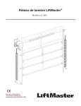
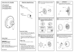
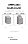
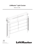
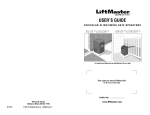
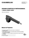
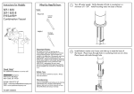
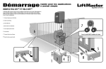
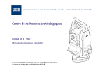
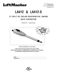
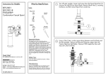
LIFTMASTER®
PROTECTOR SYSTEM
MODELS CPS-RPEN4 AND CPS-RPEN4GM
To prevent possible SERIOUS INJURY or DEATH from a closing door or gate:
• Be sure to DISCONNECT POWER to the operator BEFORE installing the photoelectric sensor.
• The door or gate MUST be in the fully opened or closed position BEFORE installing the LiftMaster®
Monitored Entrapment Protection device.
• Correctly connect and align the photoelectric sensor.
• Install the photoelectric sensor beam NO HIGHER than 6" (15 cm) above the floor for door and
27.5" (69.8 cm) above grade for gate operators.
• LiftMaster® Monitored Entrapment Protection devices are for use with LiftMaster® Commercial Door
and Gate Operators ONLY. Use with ANY other product voids the warranty.
• Entrapment protection devices MUST be installed per the operator owner's manual for each Entrapment
Zone.
APPLICATION
The LiftMaster® Protector System models CPS-RPEN4 and CPS-RPEN4GM, are single-sided safety devices
providing monitored entrapment protection for use with LiftMaster® Commercial Door and Gate Operators.
The CPS-RPEN4 and CPS-RPEN4GM may be installed in areas exposed to rain or moisture. The images are for
reference and your product may look different.
Model CPS-RPEN4 (LiftMaster® Commercial
Door Operators)
Model CPS-RPEN4GM (LiftMaster®
Gate Operators)
Logic 4
FDCL Commercial Door Operator
CSL24V Series
RSW12V Series
Medium Duty Logic
FDOA Commercial Door Operator
CSW24V Series
LA400
FDC Commercial Door
Operator
FDOB Commercial Door Operator
RSL12V Series
LA412
LA500
CARTON INVENTORY
Reflectors Support Bracket . . . . . . . . . . . . . . . . . . (1)
Installation Instruction . . . . . . . . . . . . . . . . . . . . . (1)
Self-tapping Screws . . . . . . . . . . . . . . . . . . . . . . . (4)
Photoelectric Sensor. . . . . . . . . . . . . . . . . . . . . . . (1)
Mounting Brackets . . . . . . . . . . . . . . . . . . . . . . . . (2)
Reflectors . . . . . . . . . . . . . . . . . . . . . . . . . . . . . . . (2)
LIFTMASTER® PROTECTOR SYSTEM
IMPORTANT INFORMATION ABOUT THE PHOTOELECTRIC SENSOR
Be sure power to the operator is disconnected.
When properly connected and aligned, the photoelectric sensor will detect an obstruction in the path of its
beam. If an obstruction breaks the beam while the door/gate is closing, the operator will stop and typically
reverse to the full open position.
The sensor must be installed so that it faces the reflector across the entrapment zone, no more than
6" (15 cm) above the floor for a door and no more than 27.5" (69.6 cm) above grade for a gate. Minimum
installation width of 5 feet and maximum width of 50 feet. The devices can either be installed on the left or right
of the entrapment zone.
The brackets must be securely fastened to a solid surface such as the wall framing. If installing in masonry
construction, add a piece of wood at each location to avoid drilling extra holes in masonry if repositioning is
necessary.
The invisible light beam path must be unobstructed. No part of the gate or door (or door tracks, springs,
hinges, rollers or other hardware) may interrupt the beam while the door/gate is closing.
1
ENTRAPMENT ZONES
Make sure the brackets are aligned so the photoelectric sensor and reflector will face each other across the
entrapment zone as illustrated. Determine the configuration for your brackets.
COMMERCIAL DOOR APPLICATION (MODEL CPS-RPEN4)
COMMERCIAL DOOR ENTRAPMENT ZONE
Photoelectric
Sensor
Entrapment Zone
Reflector
Invisible Light Beam
Protection Area
6" (15 cm) max. above the
floor and away from the door.
6" (15 cm) max. above the
floor and away from the door.
Facing the door from inside the building
(installation procedures are the same for all door types).
GATE APPLICATION (MODEL CPS-RPEN4GM)
SLIDE GATE ENTRAPMENT ZONES
Reflector
Photoelectric
Sensor
Photoelectric
Sensor
Reflector
!
ey
id t
s er
In p
ro
P
PrOuts
op id
ert e
y
e
id ty
ts r
u e
O op
r
P
e y
id rt
s e
In op
r
P
SWING GATE ENTRAPMENT ZONES
Photoelectric
Sensor
Photoelectric
Sensor
Reflector
!
!
2
Reflector
COMMERCIAL DOOR APPLICATION
INSTALLATION
1. Assemble reflector.
2. Slide the photoelectric sensor and the reflector onto the mounting brackets and secure with self-tapping
screws provided.
FLOOR MOUNT
WALL MOUNT
Photoelectric
Sensor
Reflector
Photoelectric
Sensor
Reflector
3. Attach mounting bracket to solid surface with hardware (not provided).
NOTE: Track mounting is not recommended.
DIRECT MOUNT
(WITHOUT MOUNTING BRACKET)
FLOOR MOUNT
WALL MOUNT
Hardware
(Not provided)
Hardware
(Not provided)
6"
6"
6"
Hardware
(Not provided)
3
WIRING CONNECTIONS
Be sure power to the operator is disconnected. Do not run control wiring in the same conduit
with AC power.
The wire cable is intended to aid in installation to either a junction box on the wall or can be routed through
the control station mounted next to the door allowing the wires to run in the same conduit as the controls. The
photoelectric sensor also is capable of receiving a 1/2" thread conduit.
Connect the photoelectric sensor as illustrated below for your operator type. The wiring is polarity sensitive so
make certain to wire as indicated below.
7
6
5
4
STOP
3
LEARN
1
2
D14
LED
POWER
24VAC
TIMER
DEFEAT
3-PHASE
COMMON
TTC
Brown
TIMER
ENABLE
EDGE:
OPEN
3
CLOSE
Control Board
Control Board
COMMERCIAL DOOR OPERATORS MODELS FDC, FDCL, FDOA, AND FDOB
J2
13 14 15 16 17 18 19 20 21 22 23 24
1 2
3 4
5 6 7 8
9 10 11 12
Blue
Brown
Control Board
4
Blue
MAS
LMEP:
Blue
TTC
^^^^
24VAC
1-PHASE
LMEP1 LMEP2 COM INTRLK STOP CLOSE OPEN
LOGIC 4
CLOSE OPEN
MEDIUM DUTY LOGIC
Brown
GATE APPLICATION
INSTALLATION
Install the photoelectric sensors and reflector up to 5" (12.7 cm) maximum from the gate.
Wall or Fence
Edge of Gate Panel
5" (12.7 cm) max. gap
Invisible Light Beam
Photoelectric
Sensor
Mounting
Post
1. Assemble reflector.
2. Slide the photoelectric sensor and the reflector onto the mounting brackets and secure with self-tapping
screws provided.
Photoelectric Sensor
Reflector
5
3. Attach mounting bracket to solid surface with hardware (not provided).
POST MOUNT WITH BRACKET (PROVIDED)
WALL MOUNT WITH BRACKET (PROVIDED)
Hardware
(Not provided)
Hardware
(Not provided)
27.5" maximum
above grade
27.5" maximum
above grade
GROUND
GROUND
MOUNTING WITH BANDING TECHNIQUE
Photoelectric Sensor
Reflector
27.5" maximum
above grade
27.5" maximum
above grade
GROUND
GROUND
DIRECT MOUNT (WITHOUT BRACKET PROVIDED)
Reflector
Photoelectric Sensor
Hardware
(Not provided)
Hardware
(Not provided)
27.5"
maximum
above grade
27.5"
maximum
above grade
GROUND
GROUND
6
WIRING CONNECTIONS
Be sure power to the operator is disconnected.
The photoelectric sensor is capable of receiving a 1/2" threaded conduit. Connect the photoelectric sensor
as illustrated below for your operator type. The wiring is polarity sensitive, connect the BLUE wire to the '-'
terminal and the BROWN wire to the '+' terminal.
MODELS CSL24V SERIES AND CSW24V SERIES
MODEL LA500 SERIES
STOP
GNOSTIC
CODES
SHADOW
CLOSE
EYES/
Sensor for CLOSE
cycle.
-
-
Sensor for CLOSE
cycle.
EXIT
INTERRUPT
+
-
+
+
+
-
+
+
-
Sensor for OPEN
cycle.
Control Board
5
Control Board
MODELS LA412, RSW12V, AND RSL12V SERIES
+
Sensor for OPEN cycle.
+
Sensor for OPEN cycle.
+
Sensor for CLOSE cycle.
Control Board
R2Ø7
MODEL LA400 SERIES
Z2Ø
R227
OPEN EDGE/
PHOTO
+
Sensor for OPEN cycle.
R224
Z22
R92
Z9
OPEN
PHOTO
+
Sensor for OPEN cycle.
R91
R94
Z8
CLOSE
PHOTO
R93
+
Sensor for CLOSE cycle.
24V
Control Board
SWITCHED
7
Sensor for OPEN
cycle.
ALIGN THE PHOTOELECTRIC SENSOR AND REFLECTOR
The photoelectric sensor and reflectors must be on the same horizontal plane to each other. When properly
wired and aligned the amber LED within the photoelectric sensor will not be illuminated. The alignment LED
within the photoelectric sensor will blink rapidly when the eye is not at the optimal positioning. If the LED is
solidly illuminated this indicates it is powered up properly and is not aligned with the reflector.
TEST THE LIFTMASTER® PROTECTOR SYSTEM
Commercial door installations:
The photoelectric sensor works on the close cycle on a LiftMaster® commercial door operator only. With
the door in the full open position place an obstruction in the path of the photoelectric sensor and then try a
CLOSE command. The operator should not move. Now remove the obstruction and give the operator a close
command. The door should close and when the path of the photoelectric sensor is obstructed the door should
reverse.
Gate installations:
The photoelectric sensor can be installed to work on either the open or closing cycles. Refer to the gate
operator installation manual for more information.
TROUBLESHOOTING
Symptom
Cause
Resolution
No alignment LED seen
1. Not wired properly.
2. Wired properly and aligned with
reflector.
1. Check wiring. Polarity sensitive.
2. None. Working properly.
Alignment LED on solid
Wired properly but NOT aligned with
the reflector.
Adjust photoelectric sensor to reflector
until the LED goes out.
Alignment LED blinking
Indicates the photoelectric sensor is
not optimally aligned with the reflector.
Adjust photoelectric sensor to reflector
until the LED goes out.
REPLACEMENT PARTS LIST
P/N:
Description
RPEN4-BKT
Mounting Bracket
RPEN4-RFLCTR
Reflectors with Support Bracket
1-800-528-2806
www.liftmaster.com
01-36737
© 2012, The Chamberlain Group, Inc.
All Rights Reserved
LIFTMASTER®
PROTECTOR SYSTEM
MODÈLES CPS-RPEN4 ET CPS-RPEN4GM
AVERTISSEMENT
Pour prévenir d'éventuelles BLESSURES GRAVES, voire MORTELLES lorsqu’une porte un portail se ferme :
• S’assurer de DÉBRANCHER L’ALIMENTATION au système AVANT d’installer le capteur photoélectrique.
• La porte ou le portail DOIT être en position complètement ouverte ou fermée AVANT d’installer le dispositif de
protection contre le piégeage avec surveillance LiftMaster®.
• Connecter et aligner correctement le détecteur photoélectrique.
• Installer le capteur photoélectrique afin que son faisceau se trouve à une hauteur NE DÉPASSANT PAS 6 po
(15 cm) au-dessus du sol et 27,5 po (69,8 cm) au-dessus du sol pour les actionneurs de portail.
• Les dispositifs de protection contre le piégeage LiftMaster® avec surveillance doivent être utilisés UNIQUEMENT
avec les actionneurs de porte et de portail commerciaux LiftMaster. L'utilisation avec TOUT autre produit annule
la garantie.
• Les dispositifs de protection contre le piégeage DOIVENT être installés selon les instructions fournies dans le
manuel du propriétaire pour chaque zone de piégeage.
APPLICATION
Les modèles CPS-RPEN4 et CPS-RPEN4GM LiftMaster® Protector System sont des dispositifs de sécurité simples
fournissant une protection surveillée contre le piégeage à utiliser avec les actionneurs de porte et de portail
commerciaux LiftMaster®.
Les modèles CPS-RPEN4 et CPS-RPEN4GM peuvent être installés dans des endroits exposés à la pluie ou à l’humidité.
Les illustrations de ce mode d’emploi ne servent qu’à titre de référence. Votre appareil peut avoir un aspect différent.
Modèle CPS-RPEN4 (Actionneurs de porte
commerciaux LiftMaster®)
Modèle CPS-RPEN4GM (Actionneurs de
portail LiftMaster®)
Logic 4
Actionneur de porte commercial FDCL
Série CSL24V
Série RSW12V
Logique de gamme
Intermédiaire
Actionneur de porte commercial
FDOA
Série CSW24V
LA400
Actionneur de porte
commercial FDC
Actionneur de porte commercial
FDOB
Série RSL12V
LA412
LA500
INVENTAIRE DE L'EMBALLAGE
Support de retenue des réflecteurs . . . . . . . . . . . . . . . (1)
Instructions d’installation . . . . . . . . . . . . . . . . . . . . . . (1)
Vis autotaraudeuses . . . . . . . . . . . . . . . . . . . . . . . . . . (4)
Capteur photoélectrique . . . . . . . . . . . . . . . . . . . . . . . (1)
Supports de montage . . . . . . . . . . . . . . . . . . . . . . . . . (2)
Réflecteurs . . . . . . . . . . . . . . . . . . . . . . . . . . . . . . . . . (2)
SYSTÈME LIFTMASTER® PROTECTOR SYSTEM
IMPORTANTE INFORMATION AU SUJET DU CAPTEUR PHOTOÉLECTRIQUE
Vérifier que l’alimentation électrique du dispositif est débranchée.
Lorsqu’il est correctement connecté et aligné, le capteur photoélectrique détectera un obstacle dans le rayon de son
faisceau de lumière invisible. Si un obstacle entre dans le rayon du faisceau pendant que la porte/le portail se ferme,
celle-ci ou celui-ci s'arrêtera et inversera sa course pour revenir en position complètement ouverte.
Le capteur doit être installé de manière à faire face au réflecteur situé de l’autre côté de la zone de piégeage à 6 po
(15 cm) au-dessus du sol pour une porte et à 27,5 po (69,8 cm) tout au plus au-dessus du sol pour un portail. Largeur
d’installation minimale de 5 pi (1,52 m) et largeur maximale de 50 pi (15,2 m). Les dispositifs peuvent être installés à
gauche ou à droite de la zone de piégeage.
Les supports doivent être bien vissés à une surface solide comme la charpente d’un mur. Si la pose se fait dans
une construction en maçonnerie, ajouter un morceau de bois à chaque endroit pour éviter de percer des trous
supplémentaires dans la maçonnerie si un repositionnement est nécessaire.
Il ne doit y avoir aucun obstacle dans le rayon du faisceau de lumière invisible. Aucune partie du portail ou de la porte
(ni les guides, les ressorts, les charnières, les rouleaux ou autres fixations) ne doit interrompre le faisceau pendant
que la porte/le portail se ferme.
9
ZONES DE PIÉGEAGE
S’assurer que les supports sont alignés de sorte que le capteur photoélectrique et le réflecteur se feront face de chaque
côté de la zone de piégeage comme illustré. Déterminer la configuration de vos supports.
APPLICATION POUR PORTE COMMERCIALE (MODÈLE CPS-RPEN4)
ZONE DE PIÉGEAGE DE PORTE COMMERCIALE
Capteur
photoélectrique
Zone de piégeage
Réflecteur
Zone de protection du
faisceau de lumière invisible
6 po (15 cm) max. au-dessus
du sol et à l’écart de la porte.
6 po (15 cm) max. au-dessus
du sol et à l’écart de la porte.
Faisant face à la porte depuis l’intérieur de l’immeuble
(les directives d’installation sont les mêmes pour tous les types de porte).
APPLICATION POUR PORTAIL (MODÈLE CPS-RPEN4GM)
ZONES DE PIÉGEAGE DE PORTAIL COULISSANT
Réflecteur
Capteur
photoélectrique
Capteur
photoélectrique
Réflecteur
e
d
r é
u t
e ié
ri pr
té ro
In p
la
e
d
r é
u t
e ié
ri pr
té o
x r
E p
la
s g
e a
n e
o g
Z ié
P
e
d
!
Zo
e
ne
e
d
r é
u t
e ié
ri pr
té ro
In p
la
e
d
r é
u t
e ié
ri pr
té o
x r
E p
la
sd
eP
iég
ea
ge
ZONES DE PIÉGEAGE DE PORTAIL PIVOTANT
Capteur
photoélectrique
Capteur
photoélectrique
Réflecteur
!
Réflecteur
!
Zo
Pi ne
ég s
ea de
ge
Zo
ne
10
sd
e
Pié
ge
ag
e
APPLICATION POUR PORTE COMMERCIALE
INSTALLATION
1. Assembler le réflecteur.
2. Faire glisser le capteur photoélectrique et le réflecteur sur les supports de montage et les fixer avec les vis
autotaraudeuses fournies à cet effet.
MONTAGE AU SOL
MONTAGE AU MUR
Capteur
photoélectrique
Réflecteur
Réflecteur
Capteur
photoélectrique
3. Fixer le support de montage à une surface solide avec la visserie (non fournie).
REMARQUE : Le montage des guides n’est pas recommandé.
MONTAGE AU SOL
MONTAGE AU MUR
MONTAGE DIRECT
(SANS SUPPORT DE MONTAGE)
Visserie
(non fournie)
Visserie
(non fournie)
6 po
6 po
6 po
Visserie
(non fournie)
11
CONNEXIONS DE CÂBLAGE
Vérifier que l’alimentation électrique du dispositif est débranchée. Ne pas acheminer le câblage de commande
dans la même conduite que le câblage d’alimentation CA.
Le câble métallique est prévu pour aider à l’installation d’une boîte de connexion au mur ou il peut être
acheminé par le poste de commande monté à côté de la porte permettant aux fils d’être acheminés dans la
même conduite que les dispositifs de commande. Le capteur photoélectrique peut aussi recevoir une conduite
filetée de 1/2 po.
Connecter le capteur photoélectrique comme illustré ci-dessous pour votre type d’actionneur. Le câblage est
sensible à la polarité. S’assurer que le câblage est installé comme indiqué ci-dessous.
LMEP1 LMEP2 COM INTRLK STOP CLOSE OPEN
4
1
2
3
LEARN
D14
LED
24VAC
POWER
24VAC
TIMER
DEFEAT
3-PHASE
COMMON
TTC
Marron
TIMER
ENABLE
EDGE:
OPEN
3
CLOSE
Tableau de commande
Tableau de commande
MODÈLES D’ACTIONNEUR DE PORTE COMMERCIAL FDC, FDCL, FDOA ET FDOB
J2
13 14 15 16 17 18 19 20 21 22 23 24
1 2
3 4
5 6 7 8
9 10 11 12
Bleu
Marron
Tableau de commande
12
Bleu
MAS
LMEP:
Bleu
TTC
^^^^
LOGIC 4
1-PHASE
STOP
5
6
7
CLOSE OPEN
LOGIQUE DE GAMME INTERMÉDIAIRE
Marron
APPLICATION POUR PORTAIL
INSTALLATION
Installer les capteurs photoélectriques et le réflecteur à une distance maximale de 5 po (12,7 cm) du portail.
Mur ou clôture
Bord ou panneau du portail
Écart max. de 5 po (12,7 cm)
Faisceau de lumière invisible
Capteur
photoélectrique
Pilier de
montage
1. Assembler le réflecteur.
2. Faire glisser le capteur photoélectrique et le réflecteur sur les supports de montage et les fixer avec les vis
autotaraudeuses fournies à cet effet.
Capteur photoélectrique
13
Réflecteur
3. Fixer le support de montage à une surface solide avec la visserie (non fournie).
MONTAGE SUR PILIER AVEC SUPPORT (FOURNI)
MONTAGE AU MUR AVEC SUPPORT (FOURNI)
Visserie
(non fournie)
Visserie
(non fournie)
27,5 po (69,8 cm)
au-dessus du sol
27,5 po (69,8 cm)
au-dessus du sol
SOL
SOL
MONTAGE AVEC BAGUE
Capteur photoélectrique
Réflecteur
27,5 po (69,8 cm)
au-dessus du sol
27,5 po (69,8 cm)
au-dessus du sol
SOL
SOL
MONTAGE DIRECT (SANS SUPPORT FOURNI)
Réflecteur
Capteur photoélectrique
Visserie
(non fournie)
Visserie
(non fournie)
27,5 po (69,8 cm)
au-dessus du sol
27,5 po (69,8 cm)
au-dessus
du sol
SOL
SOL
14
CONNEXIONS DE CÂBLAGE
Vérifier que l’alimentation électrique du dispositif est débranchée.
Le capteur photoélectrique peut aussi recevoir une conduite filetée de 1/2 po. Connecter le capteur photoélectrique
comme illustré ci-dessous pour le type d’actionneur. Le câblage est sensible à la polarité, connecter le câble BLEU à la
borne « - » et le câble MARRON à la borne « + ».
MODÈLES DE SÉRIES CSL24V ET CSW24V
MODÈLE DE SÉRIE LA500
STOP
EXIT
SHADOW
CLOSE
EYES/
Capteur pour cycle
FERMÉ.
-
-
Capteur pour cycle
FERMÉ.
GNOSTIC
CODES
INTERRUPT
+
-
+
+
+
-
+
+
-
Capteur pour cycle
OUVERT.
Tableau de commande
5
Tableau de commande
MODÈLES DE SÉRIES LA412, RSW12V ET RSL12V
+
Capteur pour cycle OUVERT.
+
Capteur pour cycle OUVERT.
+
Capteur pour cycle FERMÉ.
Tableau de commande
R2Ø7
MODÈLE DE SÉRIE LA400
Z2Ø
R227
OPEN EDGE/
PHOTO
+
R224
Capteur pour cycle OUVERT.
Z22
R92
Z9
OPEN
PHOTO
+
Capteur pour cycle OUVERT.
R91
R94
Z8
CLOSE
PHOTO
R93
+
Capteur pour cycle FERMÉ.
24V
Tableau de commande
SWITCHED
15
Capteur pour cycle
OUVERT.
ALIGNER LE CAPTEUR PHOTOÉLECTRIQUE ET LE RÉFLECTEUR
Le capteur photoélectrique et les réflecteurs doivent être sur le même plan horizontal. Si elle est adéquatement
câblée et alignée, la DEL ambre dans le capteur photoélectrique ne s’allumera pas. La DEL d’alignement dans le
capteur photoélectrique clignotera rapidement lorsque l’œil ne se trouve pas à la position optimale. Si la DEL s’allume
constamment, cela indique qu’elle est correctement alimentée, mais qu’elle n’est pas alignée sur le réflecteur.
TESTER LE SYSTÈME LIFTMASTER® PROTECTOR SYSTEM
Installations pour porte commerciale :
Le capteur photoélectrique fonctionne uniquement sur le cycle de fermeture d’un actionneur de porte
commercial LiftMaster®. Lorsque la porte est en position complètement ouverte, placer un obstacle dans le
rayon du capteur photoélectrique, puis essayer une commande de FERMETURE. L’actionneur ne devrait pas
bouger. Ensuite, retirer l’obstacle et donner à l’actionneur une commande de fermeture. La porte devrait se
fermer et lorsqu’un obstacle se trouve dans le rayon du capteur photoélectrique, la porte devrait inverser sa
course.
Installations pour portail :
Le capteur photoélectrique peut être installé de manière à fonctionner sur les cycles d’ouverture ou de fermeture.
Consulter le manuel d’installation de l’actionneur du portail pour plus d’information.
DÉPANNAGE
Symptôme
Cause
Solution
DEL d’alignement non
visible
1. Câblage incorrect.
2. Câblée et alignée correctement sur le
réflecteur.
1. Vérifier le câblage. Sensible à la
polarité.
2. Rien à faire. Fonctionne correctement.
DEL d’alignement
allumée constamment
Câblée et alignée correctement, MAIS non
alignée sur le réflecteur.
Ajuster le capteur photoélectrique jusqu’à
ce que la DEL s’éteigne.
La DEL d’alignement
clignote
Indique que le capteur photoélectrique
n’est pas aligné de manière optimale sur
le réflecteur.
Ajuster le capteur photoélectrique jusqu’à
ce que la DEL s’éteigne.
LISTE DES PIÈCES DE RECHANGE
No de pièce :
Description
RPEN4-BKT
Support de montage
RPEN4-RFLCTR
Réflecteurs avec support de montage
1-800-528-2806
www.liftmaster.com
01-36737B
© 2012, The Chamberlain Group, Inc.
Touts droits réservés