1
INSTALLATION MANUAL
PROFIL100EINT
Illuminated Mullion Weatherproof Keypad Self Contained
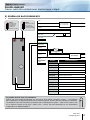
5] WIRING DIAGRAM
Black
INT2 :
Memory reset
switch
(set the switch
to ON).
INT1 :
Code change
by the user
(set the switch
to ON).
Input voltage
12 to 24V ac
or 12 to 48V dc
Red
230V
Purple
Pink
Light bleu
H1
Light green
INT1
INT2
Dark green
Dark blue
Brown
Orange
Transmission strike
V
Locked power
supply
Yellow
230V
White
Grey
Outputs
Black
Description
Input voltage 12V to 24V ac or 12V to 48V dc
Red
Power supply of 12V to 24V ac or 12V to 48V dc
Pink
Request-to-exit input relay 1
Purple
Common
Light blue
Timer Contact
Dark blue
N/C contact relay 2
Dark green
Common relay 2
Light green
N/O contact relay 2
Orange
N/C contact relay 1
Yellow
Common relay 1
Brown
N/O contact relay 1
white
Output to prevent removal
Grey
Output to prevent removal
This product is delivered with a varistor.
The varistor must be installed directly on the terminals of the strike (electromagnetic lock, motor, etc.)
controlled by the device. If the device operates with several strikes, each must be equipped with a varistor.
The varistor prevents voltage surges caused by the coil of the strike – self effect. If the “shear lock” type of
electromagnetic lock is used, it must be connected to a separate power supply from the PROFIL100EINT!
4
cdvi.com
cdvigroup.com