1
INSTALLATION MANUAL
CA-A482-P
Destination reporting module
Normally, when a user presents their access card to the reader in the elevator car,
the CA-A480-A Elevator Controller will activate and allow access to all the floors that
the user is allowed to. Though the controller will register the event, if the user has
access to more than one floor, you won’t know which floor the user has accessed.
With the Destination Reporting Module (DRM), the controller can register the user
who accessed the elevator and which floor was accessed, thus supplying an effective
floor trace for each card holder. Destination Reporting is also known as One Card,
One Floor operation as it only allows one floor selection to be made per presentation
of the card.
BASIC OPERATION
The DRM has 16 Floor Selection Inputs (one for each floor control relay of the CA-A480-A). A person presenting their card will be allowed to select a floor that they have access to. Pressing one of the connected elevator floor buttons will only activate the floor control relay corresponding to the selected floor thus allowing
access to the desired floor. The event will be logged through the controller as an “Access granted valid floor
selection” with the floor that was selected.
In the case of a floor being selected that the user does not have access to, the event “Invalid Floor Selection”
will be generated and the user will need to present their card again and then select another floor.
In all cases, once a card is presented, the user can only select one floor. Once the floor is selected (by pressing the desired elevator floor button), the user must present their card again in order to select another floor
even if the floor selected was an incorrect one.
MOUNTING THE DRM ON TO THE CA-A480-A ELEVATOR CONTROLLER
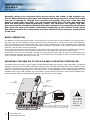
The DRM connects directly to the CA-A480-A’s DRM Module header plug using a 14-pin flat cable. The DRM is
designed to be mounted on plastic standoffs (supplied with the DRM) and fastened to the CA-A480-A using
4 screws. The DRM comes with 16 floor selection inputs, one for each floor control relay on the CA-A480-A.
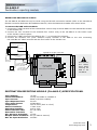
Before connecting the DRM make sure that DIP switches 7 (DRM ENABLED) and 8 (PWR OFF/ON) from the
CA-A480-A are in the “ON” position. For information on the Elevator Controller, refer to the CA-A480-A Elevator Controller Reference & Installation Manual. See below for more details.
DRM
(CA-A482-P)
14-pin Flat
Cable
CA-A480-A
Elevator Controller
1 2 3 4 5 6 7 8
ON
Plastic Standoffs
(x4)
ADDRESS 1
ADDRESS 2
ADDRESS 4
ADDRESS 8
RLY COMMS
RLY OFF/ON
DRM ENABLED
PWR OFF/ON
Before connecting the DRM to the CA-A480-A, DIP
switches 7 (DRM ENABLED) and 8 (PWR OFF/ON)
form the CA-A480-A must be in the "ON" position.
2
www.cdvi.com
www.cdvigroup.com
Disconnect AC
and battery
power before
mounting the
DRM to the
CA-A480-A.