1
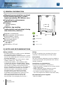
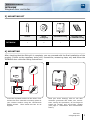
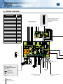
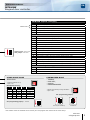
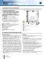
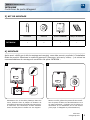
FR
FRANCAIS
EN
ENGLISH
INTBUSW
Wiegand door controller
Contrôleur de porte Wiegand
Range: Integrated access control / Gamme: Contrôle d’accès intégré
INSTALLATION MANUAL
MANUEL D’INSTALLATION
Group Products
INSTALLATION MANUAL
EN
INTBUSW
Wiegand door controller
1] GENERAL INFORMATION
Wiegand communications protocol
with multitechnologies® reader
heads (proximity, RF, Mifare®, etc.)
Centralised or autonomous
operation modes.
2 relays:
- locking system,
- alarm.
Contacts: tag reading
authorization and opening/closing
door detection (alarms).
Supplied in a sealed box.
Central controller communication
by BUS RS485 (3 wires).
Connection of an exterior
and exit push button.
Operating voltage:
- 12 V AC/DC
- 24 V DC.
Consumption: 150 mA.
WEEE
CE Certification
IP52
-20°C to +70°C
2] NOTES AND RECOMMENDATIONS
Wiring reminder
- the distance between a reader and the (INTBUSW)
door controller is 50m maximum.
- the distance between a central controller or panel
and the last (INTBUSW) door controller may be up
to 1000m maximum.
- take care not to pass your wires close to «High
voltage» cables (e.g.: 230 V AC).
- recommended cables > SYT1 shielded cable,
1 twisted pair 8/10ths (shielded cables), please
read the article below: « A EIA-485 Bus network
can connect in parallel several devices which
have a transmitter and a receiver. The maximum
length is 1220 meters between the controller
and the last reader. If the distance exceeds
10 meters then it is necessary to connect
the GND (0V) between each devices (then
the RS485 communication bus requires 3 core
cable, 2 plus the shield) to prevent, that
the voltage between the OV and the OV
and the GND, from damaging the devices.»
2
cdvi.com
cdvigroup.com
Fitting
In order to optimise the mounting of the door
controller, it should be fitted on a flat surface.
Environment
The door controller absolutely must be installed in
a closed environment and protected from exterior
climatic conditions.
Installation recommendations
To protect the installation, remember to:
- install the varistor in parallel on the locking system
power supply side.
- install a 120 ohm resistor between A and B
on the last BUS RS485 door controller.
- The readers must be installed one at a time
(can not program the readers at the same time).
Recommended power supplies
- ARD12 or BS60.
INSTALLATION MANUAL
EN
INTBUSW
Wiegand door controller
3] MOUNTING KIT
INTBUSW
Varistor
Wiring
sealing cap
INTBUSW housing
1
2
1
Mounting plate
for INTBUW housing
4] MOUNTING
After checking that the fitting kit is complete, you can proceed with the final installation of the
product. Collect up the necessary tools (drill, screwdriver, measuring tape, etc) and follow the
INTBUSW door controller fitting instructions:
1
2
Insert the 2 plastic anchors in the holes. Then
mount the door controller mounting plate on
your chosen surface using the countersunk
Phillips screws. Then mount the box on its
support.
Feed your wires through, slide on the door
controller grommets and make your connections. During this procedure, do not forget to
install the varistor and end-of-loop resistor
(See page 3 «Reminders and recommendations»).
cdvi.com
cdvigroup.com
3
INSTALLATION MANUAL
EN
INTBUSW
Wiegand door controller
6] WIRING DIAGRAM
WIEGAND READERS
(CDVI RANGE)
Format
(Bits)
DGLP WLC
44
DGLP FN WLC
44
DGLI WLC
44
DGLIF WLC
44
DGLPT WLC
44
DGLP60 WLC
44
DGLPM WLC
44
DGMW
44
DTRR1434
26
GALEOW
26
RECEPTW
26
DGIDW
44
CABAPROXW
44
STARPW - STARPB
44
SOLARPW - SOLARPB
44
SOLARKPW - SOLARKPB
44
NANOPW - NANOPB
26
The format of the reader
have to be the same
than the door controller
INTBUSW
Connections to the
Wiegand reader
INTBUSW
Strike
Magnet
Varistor
SYT1 shielded
cable
Power supply
Two different configurations,
are possible:
Shielded
cable
12VDC only
(As standard)
Cut the strap
12VAC or 24VDC
Door contact (not used)
Connect E and M
4
cdvi.com
cdvigroup.com
To other door controllers
(INTBUSW)
INSTALLATION MANUAL
EN
INTBUSW
Wiegand door controller
INTBUSW (Reader controller)
Terminal block : Motherboard
150mA max.
V
Output Voltage - (To reader)
12
Output voltage + (To reader)
1
D0 - Data O (From reader)
2
Clock (From reader)
3
D1 - Data 1 (from reader)
Terminal block : Motherboard
R
N/C contact - Fail safe lock (+) - Relay 1
C
Common contact power supply (+) - Relay 1
T
N/O contact - Fail secure lock - Relay 1
R
N/C contact alarm - Relay 2
C
Common - Relay 2
T
N/O contact alarm - Relay 2
+ ~ - Input voltage 12V ac/dc or 24V dc
Without jumper : without clock
With jumper : with clock
P1
Request-to-enter input
M
Common ( P1 et P2 )
P2
Request-to-enter input
E
Door position contact, N/C (Door closed) and N/O (Door open)
L
Reader activation input (N/O) reader enabled and (N/C) reader disabled
M
Common ( E and M ) or (E and L)
A
RS485 Bus (All the A must be connected together in daisy chain)
B
RS485 Bus (All the B must be connected together in daisy chain)
Terminal block - 3 points : Piggyback board
7
Buzzer
8
LED > Green color
9
LED > Red color
STAND ALONE MODE
CENTRALIZED MODE
TELACCESS
-
- Dipswitch address set up
- Dip4 = ON
DIP SWITCH adressing
1
2
3
4
Mode
ON
ON
ON
ON
Front plate
OFF
ON
ON
ON
Reader 1
ON
OFF
ON
ON
Reader 2
OFF
OFF
ON
ON
Reader 3
ON
ON
OFF
ON
Reader 4
TERENA,
UGM-UGL,
UGP/40
PDN345BUSPROX
- Address programming during installation
- Dip4 = OFF
ST1 (Programming jumper)*
ST1 (Programming jumper)* : Normal
Normal (As standard)
Installation
* The readers must be installed one at a time (can not program the readers at the same time).
cdvi.com
cdvigroup.com
5
INSTALLATION MANUAL
INTBUSW
Wiegand door controller
EN
7] LIMITED LIFETIME WARRANTY [EXTRACT]*
CDVI warrants this product to be free from defects in material and workmanship, when it has been installed
in accordance with the manufacturer’s instructions and has not been modified or tampered with. Only product
recognized by CDVI to be defective should be returned under these warranty terms if accompanied
by an RMA (Return Material Authorization Number) provided by CDVI. CDVI, at its option, shall repair
or replace the defective product at CDVI premises or at any CDVI approved service center. This warranty
does not cover any damage due to accident, misuse, abuse or negligence. This warranty is valid only
if the product is registered, within 1 month from delivery to the final costumer. To obtain full details of this
warranty and to register the product to commence the “Limited Lifetime Warranty”, complete the enclosed
registration card and return it, either by e-mail or post, to the relevant CDVI address or completion of the
on line registration at www.cdvigroup.com. Repair or replacement of the defective product is the exclusive
remedy. CDVI shall not be liable for any incidental or consequential damages arising from any defect in, or
malfunction of, its product. In no event the entire liability can not exceed the purchase price of the product.
The CDVI local country contact details can be found on line by visiting www.cdvigroup.com or on the back
cover of the installation manual.
DISCLAIMER OF WARRANTY: EXCEPT AS STATED ABOVE, CDVI MAKES NO WARRANTIES, EITHER
EXPRESS OR IMPLIED, AS TO ANY MATTER WHATSOEVER, INCLUDING THE CONDITION OF ITS PRODUCTS,
THE TRANSPORTATION, THEIR MERCHANTABILITY OR FITNESS FOR ANY PARTICULAR PURPOSE.
8] NOTES
*Refer to Limited Lifetime Warranty conditions
6
cdvi.com
cdvigroup.com
INSTALLATION MANUAL
EN
INTBUSW
Wiegand door controller
cdvi.com
cdvigroup.com
7
MANUEL D’INSTALLATION
FR
INTBUSW
Contrôleur de porte Wiegand
1] PRESENTATION DU PRODUIT
Protocole Wiegand de
communication avec les têtes
de lecture multitechnologies®
(proximité, Radio, Mifare®, ...)
Mode centralisé ou autonome.
2 relais :
- système de verrouillage,
- alarme.
Contacts : autorisation lecture
du badge et détection ouverture/
fermeture des portes (alarmes).
Fourni en boitier.
Liaison centrale par BUS RS485 (3fils).
Connexion d’un bouton poussoir
extérieur et de sortie.
Alimentation :
- 12 V AC/DC
- 24 V DC.
Consommations : 150 mA.
DEEE
Certification CE
IP52
-20°C à +70°C
2] RAPPELS ET RECOMMANDATIONS
Rappel de câblage
- la distance entre un lecteur et le contrôleur de porte
(INTBUSW) doit être de 50 m maximum.
- la distance entre une centrale ou platine jusqu’au
dernier contrôleur de porte (INTBUSW) peut
atteindre 1000 m maximum.
- attention de ne pas passer vos fils à proximité
de câbles «Courant fort» (ex : 230 V AC).
- câbles préconisés > 1 paires torsadée, SYT1 blindé
8/10ème (Norme EIA-485), se référer à l’article
ci-dessous : « Une ligne EIA-485 peut interconnecter
en parallèle plusieurs dispositifs, dotés chacun d’un
émetteur et d’un récepteur. Des distances maximales
de l’ordre du kilomètre sont possibles, ceci est
fonction des débits configurés. L’expérience pratique
montre néanmoins que si la longueur de ligne de
transmission dépasse une dizaine de mètres, il est
nécessaire de raccorder ensemble les potentiels de
référence (0V) de tous les dispositifs (dans ce cas
la liaison RS485 nécessite en réalité trois fils – deux
plus le blindage) pour s’assurer que les tensions
entre masses et entre masses et terres ne soient
pas destructrices. »
8
cdvi.com
cdvigroup.com
Montage
Afin d’optimiser la fixation du contrôleur de porte,
privilégiez les surfaces planes.
Environnement
Le contrôleur de porte doit être impérativement
installée dans un environnement clos et protégée
des conditions climatiques extérieures.
Recommandations d’installation
Pour sécuriser l’installation, n’oubliez pas de :
- placer la varistance sur le système de verrouillage,
en parallèle, au niveau de l’alimentation.
- placer une résistance de 120 ohms, entre A et B,
sur le dernier contrôleur de porte du BUS RS485.
- Les lecteurs ne peuvent être programmés que l’un
après l’autre (la programmation simultanée
des lecteurs n’est pas possible).
Alimentations préconisées
Deux alimentations sont adaptées pour ce contrôleur
de porte (INTBUSW) : ARD12 et BS60.
MANUEL D’INSTALLATION
FR
INTBUSW
Contrôleur de porte Wiegand
3] KIT DE MONTAGE
INTBUSW
Varistance
Passe-fil
Boitier INTBUSW
Plaque de fixation
1
2
1
1
4] MONTAGE
Après avoir vérifié que le kit de montage est complet, vous allez pouvoir procéder à l’installation
finale du produit. Réunissez le matériel approprié (Perceuse, tournevis, mètre,...) et suivez les
recommandations de montage du contrôleur de porte INTBUSW :
1
2
Positionnez les 2 chevilles plastique dans les
trous. Ensuite fixez la plaque de fixation du
contrôleur de porte sur la surface de votre choix,
à l’aide des vis cruciformes à têtes fraisées.
Venez ensuite placer le boîtier sur son support.
Passez vos fils, glissez les passe-fils du contrôleur de porte et faites vos branchements. Lors
de cette opération, n’oubliez pas de placer la
varistance et la résistance de fin de boucle
(Voir page 3 «Rappels et préconisations»).
cdvi.com
cdvigroup.com
9
MANUEL D’INSTALLATION
FR
INTBUSW
Contrôleur de porte Wiegand
6] RACCORDEMENTS
LECTEURS WIEGAND
DE LA GAMME CDVI
Format
(Bits)
DGLP WLC
44
DGLP FN WLC
44
DGLI WLC
44
DGLIF WLC
44
DGLPT WLC
44
DGLP60 WLC
44
DGLPM WLC
44
DGMW
44
DTRR1434
26
GALEOW
26
RECEPTW
26
DGIDW
44
CABAPROXW
44
STARPW - STARPB
44
SOLARPW - SOLARPB
44
SOLARKPW - SOLARKPB
44
NANOPW - NANOPB
26
Le format du lecteur doit
être identique au format
du contrôleur de porte
INTBUSW
Connexion
au lecteur Wiegand
INTBUSW
Gâche
Ventouse
Varistance
Câble SYT1
blindé
Alimentation
Pour l’alimentation,
il y a deux modes possibles :
Câble de
blindage
12 V DC uniquement
(Configuration usine)
Coupez le strap
12 V AC ou 24 V DC
10
cdvi.com
cdvigroup.com
Si vous ne souhaitez
pas de gestion de l’etat
porte : Relier E et M
Vers d’autres contrôleur
de portes (INTBUSW)
MANUEL D’INSTALLATION
FR
INTBUSW
Contrôleur de porte Wiegand
INTBUSW (Contrôleur de porte)
Bornier 5 points : Carte mère
150 mA max.
V
Alimentation - (Vers lecteur)
12
Alimentation + (Vers lecteur)
1
D0 - Data O (Venant du lecteur)
2
Clock (Venant du lecteur)
3
D1 - Data 1 (Venant du lecteur)
Bornier 16 points : Carte mère
R
Contact N.F porte - Verrouillage à rupture (+) - Relais 1
C
Contact commun + Alimentation - Relais 1
T
Contact N.O porte - Verrouillage à émission - Relais 1
R
Contact N.F alarme - Relais 2
C
Contact commun - Relais 2
T
Contact N.O alarme - Relais 2
+ ~ - Alimentation 12 V AC/DC ou 24 V DC
Sans cavalier : sans clock
Avec cavalier : avec clock
P1
Bouton poussoir intérieur
M
Masse commune ( P1 et P2 )
P2
Bouton poussoir extérieur
E
Contact position porte, N.F. (Porte fermée) et N.O. (Porte ouverte)
L
Contact autorisation lecture du badge (N.O) autorisée et (N.F) interdite
M
Masse commune ( E et M ) ou (E et L)
A
Bus RS485 (tous les A doivent être reliés en série)
B
Bus RS485 (tous les B doivent être reliés en série)
Bornier 3 points : Carte fille
7
Buzzer
8
Signalisation > couleur verte
9
Signalisation > couleur rouge
MODE AUTONOME
MODE CENTRALISÉ
TELACCESS
-
- Programmation de l’adresse par dipswitch
- Dip4 = ON
Adressage DIPSWITCH
1
2
3
4
Mode
ON
ON
ON
ON
Façade
OFF
ON
ON
ON
Lecteur 1
ON
OFF
ON
ON
Lecteur 2
OFF
OFF
ON
ON
Lecteur 3
ON
ON
OFF
ON
Lecteur 4
TERENA,
UGM-UGL,
UGP/40
PDN345BUSPROX
- Programmation de l’adresse par installation
- Dip4 = OFF
ST1 (Cavalier de programmation)*
ST1 (Cavalier de programmation)* : Normal
Normal (Config. usine)
Installation
* Les lecteurs ne peuvent être programmés que l’un après l’autre (la programmation simultanée des lecteurs n’est pas possible).
cdvi.com
cdvigroup.com
11
MANUEL D’INSTALLATION
INTBUSW
Contrôleur de porte Wiegand
FR
7] CONDITIONS DE GARANTIE À VIE LIMITÉE [EXTRAIT]*
Les sociétés CDVI garantissent que ce produit est dépourvu de tout vice caché, tant dans les matériaux
que dans sa fabrication, à la condition, qu’il soit installé conformément aux préconisations du fabricant
et qu’il n’y ait pas eu d’interventions ou de modifications sur le produit. La responsabilité de CDVI se limite
à la réparation ou à l’échange du produit. CDVI n’assume aucune responsabilité concernant les dommages
sur les biens ou les personnes. Un produit reconnu défectueux par CDVI doit être retourné au serviceaprès-vente de CDVI, après l’obtention du numéro d’autorisation de Retour de Produit(s) Défectueux (RMA).
La responsabilité de CDVI se limite à la réparation ou au remplacement d’un produit ou pièces défectueuses,
en ses ateliers. L’une ou l’autre de ces interventions sont définis par le service-après-vente de CDVI.
Le préjudice imputable à CDVI ne saurait en aucun cas dépasser la valeur du produit. La responsabilité
de CDVI ne peut être engagée auprès de l’acheteur, installateur, client final ou qui que ce soit, lors de dommages
consécutifs à des imperfections ou mauvais fonctionnement du produit. Cette garantie prend effet
à la date d’enregistrement du produit auprès de CDVI, à partir de l’instant ou la date d’enregistrement est
dûment complétée, dans la limite d’un mois, après la date de livraison au client final. Pour obtenir les détails complets de cette garantie et enregistrer votre/vos produit(s) pour bénéficier de cette « Garantie à Vie
limitée ». Veuillez compléter la carte d’enregistrement présente dans la boite du produit et nous la retourner,
par email ou par courrier, à l’adresse de l’entité CDVI la plus proche ou vous enregistrer en ligne à l’adresse
www.cdvigroup.com. Les contacts des entités CDVI sont accessibles en ligne à l’adresse www.cdvigroup.com
ou au dos de la notice d’installation.
EXCLUSIONS DE LA GARANTIE : A l’EXCEPTION DES POINTS EVOQUES PRECEDEMMENT, CDVI N’APPLIQUE
AUCUNE GARANTIE, NI DELIBEREE NI TACITE, A TOUS LES PROBLEMES INCLUANT LE CONDITIONNEMENT,
LE TRANSPORT, LEUR COMMERCIALISATION OU LES CONDITIONS D’UTILISATIONS PARTICULIÈRES.
8] NOTES
*Voir conditions de garantie à vie limitée
12
cdvi.com
cdvigroup.com
MANUEL D’INSTALLATION
FR
INTBUSW
Contrôleur de porte Wiegand
cdvi.com
cdvigroup.com
13
MANUEL D’INSTALLATION
INTBUSW
Contrôleur de porte Wiegand
14
cdvi.com
cdvigroup.com
FR
MANUEL D’INSTALLATION
FR
INTBUSW
Contrôleur de porte Wiegand
cdvi.com
cdvigroup.com
15
Reference : G0301FR0317V06
Extranet : EXE-CDVI_IM INTBUSW CMYK A5 EN-FR 06
CDVI Group
FRANCE (Headquarter/Siège social)
Phone: +33 (0)1 48 91 01 02
Fax: +33 (0)1 48 91 21 21
CDVI IBÉRICA
CDVI SWEDEN
[SPAIN - PORTUGAL]
[SWEDEN - DENMARK - NORWAY - FINLAND]
CDVI
FRANCE + EXPORT
Phone: +33 (0)1 48 91 01 02
Fax: +33 (0)1 48 91 21 21
CDVI
TAIWAN
Phone: +886 (0)42471 2188
Fax: +886 (0)42471 2131
CDVI AMERICAS
CDVI
SUISSE
Phone: +41 (0)21 882 18 41
Fax: +41 (0)21 882 18 42
CDVI
ITALIA
Phone: +39 0331 97 38 08
Fax: +39 0331 97 39 70
CDVI UK
CDVI
CHINA
Phone: +86 (0)10 62414516
Fax: +86 (0)10 62414519
CDVI
MAROC
Phone: +212 (0)5 22 48 09 40
Fax: +212 (0)5 22 48 34 69
DIGIT
FRANCE
Phone: +33 (0)1 41 71 06 85
Fax: +33 (0)1 41 71 06 86
[CANADA - USA]
Phone: +1 (450) 682 7945
Fax: +1 (450) 682 9590
CDVI BENELUX
[BELGIUM - NETHERLAND - LUXEMBOURG]
Phone: +32 (0) 56 73 93 00
Fax: +32 (0) 56 73 93 05
Toutes les informations mentionnées à titre indicatif sur le présent document (photos, dessins, caractéristiques
techniques et dimensions) peuvent varier et sont susceptibles de modifications sans notification préalable.
All the information contained within this document (photos, drawing, features, specifications and dimensions)
could be perceptibly different and can be changed without prior notice.
Manufacturing Access Control since 1985
Phone: +34 (0)935 390 966
Fax: +34 (0)935 390 970
cdvigroup.com
Phone: +46 (0)31 760 19 30
Fax: +46 (0)31 748 09 30
[UNITED KINGDOM - IRELAND]
Phone: +44 (0)1628 531300
Fax: +44 (0)1628 531003