1
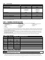
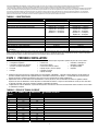
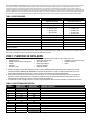
TABLE 1 - SPECIFICATIONS:
MODEL #
Max Generator Size in Watts
UTILITY MAIN breaker, Included
GEN MAIN breaker, included
Branch Circuit Breakers Provided from Factory
Max Load Combined
Max Watts @ 250 Volts
NEMA Type Enclosure
Configuration of Male Inlet
Max 1-pole Circuits* / Max 2-pole Circuits*
Min. gauge Cord Size
Required Main Breaker in load Center (installer provided)
6379
6381
7500 rated / 9300 surge
60 Amp
30 Amp
3 – 15 amp 1-pole
3 – 20 amp 1-pole
1 – 20 amp 2-pole
1 – 30 amp 2-pole
12500 rated / 15000 surge
100 Amp
50 Amp
3 – 15 amp 1-pole
3 – 20 amp 1-pole
1 – 20 amp 2-pole
1 – 30 amp 2-pole
1 – 50 amp 2-pole
50 Amp
12,500
NEMA 3R
CS6365
16 / 8
6/4 wire
2-pole 100 amp
30 Amp
7500
NEMA 3R
NEMA L14-30
16 / 8
10/4 wire
2-pole 60 amp
*Note: If Ground Fault Circuit Interrupters (GFCI) circuit breakers, Arc Fault Circuit Interrupters, or Surge Protector Circuit Breakers were used as the branch circuit protector
in the main load center, they MUST be used in the transfer switch. Because these circuit breakers typically take up more than one space, the overall maximum number of
circuits may be reduced from the number shown.
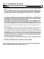
STEP 1: PLANNING YOUR INSTALLATION:
1. Determine the appliances, circuits or equipment you want to operate with generator power during a power outage, such as:
•
•
•
•
•
Refrigerator/Freezer,
Furnace Blower (gas/oil only)
TV / Radio
Lighting
Water Heater
•
•
•
•
•
Garage Door Opener
Microwave, Coffee Maker
Well / Septic Pump
Security System
Sump Pump
•
•
•
Computer, Fax and Printer, Phone
Medical Device(s)
Aquarium
2. Determine the amps required for each appliance by reading the label on the appliance. IMPORTANT: No appliance should have an amperage rating that
exceeds the GEN MAIN breaker rating in the transfer switch (See Table 1). The total amperage of all circuits can exceed the generator rating, but not all
circuits will be able to be used concurrently.
3. Assign the circuit # in the load center to a circuit (A2, B2, etc.) in the transfer switch matching the size of the circuit breaker in the load center to the
circuit breaker in the transfer switch. Once you’ve determined which circuits you want to connect and the appropriate amperage, you will be ready to
begin installing your transfer switch.
4. The location of your load center/electrical panel in your home or business will determine where the transfer switch will be installed outdoors.
TABLE 2 – CIRCUIT WORKSHEET
CIRCUIT #
MODEL 6379
MODEL 6381
A1
B1
A2
B2
A3
NA
NA
30A
30A
NA
50A
50A
30A
30A
20A
B3
A4
B4
A5
B5
A6
B6
A7
NA
15A
20A
15A
20A
20A
15A
20A
20A
20A
15A
20A
20A
15A
15A
NA
B7
20A
NA
APPLIANCE OR CIRCUIT
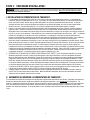
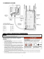
STEP 2: INSTALLATION PROCEDURE:
HAZARDOUS VOLTAGES ARE PRESENT INSIDE TRANSFER SWITCH ENCLOSURES THAT CAN CAUSE DEATH OR SEVERE PERSONAL INJURY. FOLLOW PROPER INSTALLATION,
OPERATION AND MAINTENANCE PROCEDURES TO AVOID HAZARDOUS VOLTAGES. TURN OFF THE MAIN CIRCUIT BREAKER IN THE LOAD CENTER BEFORE STARTING INSTALLATION.
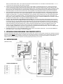
I. TRANSFER SWITCH INSTALLATION:
1.
Transfer switch can be installed on either the left or right side of the main load center. Transfer switch is provided with 21-1/2” of flexible conduit.
The connection to the main load center, using the provided wire harness, must be made through one of the two (2) knockouts (KO’s) provided in the
2