1
2.
3.
4.
5.
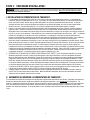
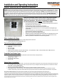
bottom of the manual transfer switch. The wire harness should enter the main load center in one of the bottom or lower side knockouts. A 1” or 11/4” KO can be cut in the lower side of the enclosure if necessary.
Remove the cover of the main load center and the transfer switch. Cut the conduit to a convenient length or use as is. Attach connectors to the
conduit. After attaching the flexible conduit to both boxes through the KOs, hold the transfer switch away from the load center against the wall on
which it is to be mounted and mark the holes on the wall for the anchoring screws. Be sure NOT to stress the flexible conduit, as it will break. (NOTE:
Mounting on LEFT side of existing load center is preferred method. Mounting to right side of existing load center and routing flexible conduit may
interfere with generator cord connection into transfer switch. Reducing washers (not provided) may be needed if using 2” KO on the bottom left.
After mounting the transfer switch to the wall, you are ready to terminate the wires in the manual transfer switch. Fish the bundle of wires provided
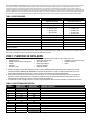
through the conduit. Strip each wire in the wire harness approximately 5/8” and insert and tighten the wires to the correspondingly marked circuit
breakers in the transfer switch. As you attach each marked wire to the circuit breaker, write on the label on the cover of the transfer switch with the
appliance on that circuit per the planning worksheet. The unmarked BLACK wires in the harness are inserted into the Utility 2-pole breaker in the
transfer switch. Attach the WHITE wire to the insulated neutral bar inside the transfer switch, and attach the GREEN wire to the ground bar. Reinstall
the dead front to the transfer switch. Cover may be re-installed and padlocked, if desired.
RECHECK TO BE SURE THE MAIN CIRCUIT BREAKER HAS BEEN TURNED OFF. The wires from the harness entering the load center can now be
terminated. Remove the wires of the appliances/loads that have been assigned to circuits in the transfer switch from the breakers in the load center.
Cut the harness wires to a convenient length and strip off approximately 5/8” and connect with the provided wire connectors (see wire connector
chart) using the appropriate labeled wire from the transfer switch. The unmarked BLACK wires in the harness are to be inserted into the NEW 2 pole
breaker (as required in the Other Items Needed section). Remove two adjacent single pole breakers from which the appliance/load wires were
removed. The 2-pole breaker should be located in a bus bar location where two adjacent full size single pole circuit breakers were removed.
Terminate the WHITE and GREEN wire in the harness in an open position in the Neutral and Ground bars respectively. If there is no separate ground
bar, insert the GREEN wire into an open position in the NEUTRAL bar, and tighten.
Reinstall the load center cover, and turn ON the MAIN breaker. Then turn ON ALL circuit breakers in both boxes. Turn on the UTILITY MAIN in the
manual transfer switch. Check that power is restored to all appliances.
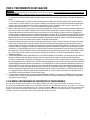
II. EXPANDING OR RECONFIGURING YOUR TRANSFER SWITCH:
This transfer switch ships from the factory with certain popular branch circuit breaker sizes. However, the circuit breaker assortment can be modified to suit specific
requirements, and this does not void the UL Listing. For example, if the 2-pole 20 amp circuit breaker is not needed, it may be removed from the panel and replaced
with any combination of the following: two separate full size breakers, four tandem (half size) breakers, one full size and two tandems, or a quad breaker. If
additional circuit(s) are added, the installer is responsible for providing appropriately sized wire(s) for each circuit.
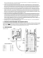
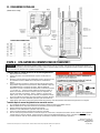
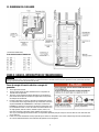
III. WIRING DIAGRAM
(Model 6381 shown)
CIRCUIT ID FOR MODEL 6381
3