1
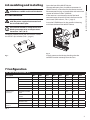
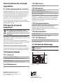
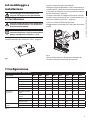
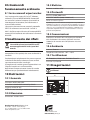
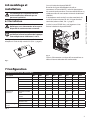
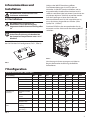
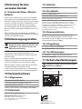
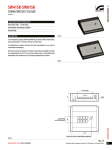
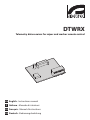
DTWRX
Telemetry data receiver for wiper and washer remote control
EN English - Instructions manual
IT Italiano - Manuale di istruzioni
FR Français - Manuel d’instructions
DE Deutsch - Bedienungslanleitung
DTWRX
Telemetry data receiver for wiper and washer remote control
1 About this manual
Before installing and using this unit, please read this
manual carefully. Be sure to keep it handy for later
reference.
1.1 Typographical conventions
DANGER!
High level hazard.
Risk of electric shock. Disconnect the
power supply before proceeding with any
operation, unless indicated otherwise.
WARNING!
Medium level hazard.
This operation is very important for the
system to function properly. Please read
the procedure described very carefully and
carry it out as instructed.
INFO
Description of system specifications.
We recommend reading this part carefully
in order to understand the subsequent
stages.
2 Notes on copyright and
information on trademarks
The quoted names of products or companies are
trademarks or registered trademarks.
3 Safety rules
The manufacturer declines all responsibility
for any damage caused by an improper use
of the appliances mentioned in this manual.
Furthermore, the manufacturer reserves
the right to modify its contents without any
prior notice. The documentation contained
in this manual has been collected with great
care, the manufacturer, however, cannot
take any liability for its use. The same thing
can be said for any person or company
involved in the creation and production of
this manual.
• The device must be installed only and exclusively
by qualified technical personnel.
• Before any technical work on the appliance,
disconnect the power supply.
• Do not use power supply cables that seem worn
or old.
• Never, under any circumstances, make any
changes or connections that are not shown in
this handbook: improper use of the appliance
can cause serious hazards, risking the safety of
personnel and of the installation.
• Use only original spare parts. Non-original spare
parts could cause fire, electrical discharge or other
hazards.
• Before proceeding with installation check the
supplied material to make sure it corresponds
to the order specification by examining the
identification labels (4.2 Product markings, page 2).
EN - English - Instructions manual 4 Identification
4.1 Product description and type
designation
The DTWRX receiver is an optional board for remote
control of wiper and washer pump. It works only
with WASPT pump series, where it can be easily
installed thanks to its connector. It allows the control
of wiper and washer functions when the housing is
stand-alone, not mounted on a P&T and then without
telemetry receiver.
4.2 Product markings
See the label attached to the outside of the package.
5 Preparing the product for
use
Any change that is not expressly approved
by the manufacturer will invalidate the
guarantee.
5.1 Unpacking and contents
5.1.1 Unpacking
When the product is delivered, make sure that the
package is intact and that there are no signs that it
has been dropped or scratched.
If there are obvious signs of damage, contact the
supplier immediately.
Keep the packaging in case you need to send the
product for repairs.
5.1.2 Contents
Check the contents to make sure they correspond
with the list of materials as below:
• Data receiver board
• Instructions manual
5.2 Safely disposing of packaging
material
The packaging material can all be recycled. The
installer technician will be responsible for separating
the material for disposal, and in any case for
compliance with the legislation in force where the
device is to be used.
Bear in mind that if the material has to be returned
due to a fault, using the original packaging for its
transport is strongly recommended.
2
6 Assembling and installing
6.3 Installation
Always make the electrical connections
with the power supply disconnected and
the circuit-breaker open.
Connect telemetry lines A and B to connector J9
(WASPT board) as described in the relative manual.
We recommend using a twisted cable with minimum
section of 0.22mm²/0.8in² (AWG24).
If the receiver is connected to one of the head
communication channels RS-485, the line must be
terminated (SW8 column, Tab. 1, page 3).
Insert the DTWRX board in the specific J8 housing
and close the box of the WASPT device.
The receiver includes a safety device that
blocks pump operation at temperatures
lower than -10°C (10°F).
Configure protocol, baud rate and receiver address
via the DS1 dip-switches (Tab. 1, page 3).
Fig. 2
Fig. 1
Supply power to the device, checking that the
controls function correctly from the start.
7 Configuration
Dip-switch configuration (DS1)
Description
Address
Protocol and
baud rate
Termination of RS485 line
SW 1
SW 2
SW 3
SW 4
SW 5
Not available
OFF
OFF
OFF
OFF
OFF
SW 6
SW 7
1
ON
OFF
OFF
OFF
OFF
2
OFF
ON
OFF
OFF
OFF
3
ON
ON
OFF
OFF
OFF
…
…
…
…
…
…
31
ON
ON
ON
ON
ON
VIDEOTEC MACRO
9600
OFF
OFF
VIDEOTEC MACRO
38400
ON
OFF
PELCO D 2400
OFF
ON
PELCO D 9600
ON
ON
SW 8
Line terminated
ON
Line not terminated
OFF
Tab. 1
3
Instructions manual - English - EN
Only specialised personnel should be
allowed to assemble and install the device.
Open the box of the WASPT device.
8 Instructions for normal
operation
8.1 Send wiper/washer controls
If Videotec keypads DCJ and DCT are used, use the
WIPER/WASHER buttons. Pressing these buttons will
activate the relative function, while releasing them
will stop execution (refer to the keypad manuals).
The devices that communicate via the PELCO D
protocol use AUX 3 and AUX 4 controls.
AUX 3 Set/Reset activates/deactivates the WIPER
function, while AUX 4 Set/Reset activates/deactivates
the WASHER function.
9 Disposal of waste
materials
This symbol mark and recycle system
are applied only to EU countries and not
applied to the countries in the other area of
the world.
Your product is designed and manufactured with
high quality materials and components which can be
recycled and reused.
This symbol means that electrical and electronic
equipment, at their end-of-life, should be disposed of
separately from your household waste.
Please dispose of this equipment at your local
Community waste collection or Recycling centre.
In the European Union there are separate collection
systems for used electrical and electronic products.
10 Technical data
10.3 Electrical
Power consumption: 0.5W
10.4 Protocols
PELCO D (2400, 9600 baud)
VIDEOTEC MACRO (9600, 38400 baud)
PELCO is registered trademark.
The product may be interfaced with devices not manufactured by
VIDEOTEC. It is possible that the interface protocols have changed or
are in a different configuration from earlier tested units by VIDEOTEC.
VIDEOTEC recommends a test prior to installation. VIDEOTEC will
not be liable for any installation costs or lost revenues in the event a
compatibility problem will occur.
10.5 Communications
Half duplex RS-485 serial interface for keypad
telemetry data reception (maximum distance
1200m/3940ft) and from SM matrix range (maximum
distance 1200m/73940ft)
10.6 Environment
Indoor / Outdoor
Operating temperature: -10°C / +50°C
10.7 Certifications
CE: EN60950-1, EN50130-4, EN55022 Class B
FCC Part 15, Class B
11 Technical drawings
The dimensions of the drawings are in
millimetres.
56
10.1 General
2 functions: WIPER, WASHER
43
31 selectable addresses through Dip Switch
Serial input RS-485
2 status LED: Stand-by and receiver control
10.2 Mechanical
Fig. 3DTWRX.
Dimensions: 43x56x13mm (1.7x2.2x0.51in)
Headquarters Italy Videotec S.p.A.
Via Friuli, 6 - I-36015 - Schio (VI) Italy
Tel. +39 0445 697411 - Fax +39 0445 697414
Email: [email protected]
www.videotec.com
MNVKDTWRX_1217_EN
DTWRX
Ricevitore dati per il controllo remoto del tergicristallo e della pompa
1 Informazioni sul presente
manuale
Prima di installare e utilizzare questa unità, leggere
attentamente questo manuale. Conservare questo
manuale a portata di mano come riferimento futuro.
1.1 Convenzioni tipografiche
PERICOLO!
Pericolosità elevata.
Rischio di scosse elettriche. Prima di
eseguire qualsiasi operazione assicurarsi di
togliere tensione al prodotto, salvo diversa
indicazione.
ATTENZIONE!
Pericolosità media.
L'operazione è molto importante per il
corretto funzionamento del sistema. Si
prega di leggere attentamente la procedura
indicata e di eseguirla secondo le modalità
previste.
INFO
Descrizione delle caratteristiche del
sistema.
Si consiglia di leggere attentamente per
comprendere le fasi successive.
2 Note sul copyright e
informazioni sui marchi
commerciali
I nomi di prodotto o di aziende citati sono marchi
commerciali o marchi commerciali registrati
appartenenti alle rispettive società.
3 Norme di sicurezza
Il produttore declina ogni responsabilità
per eventuali danni derivanti da un
uso improprio delle apparecchiature
menzionate in questo manuale. Si
riserva inoltre il diritto di modificarne il
contenuto senza preavviso. Ogni cura è
stata posta nella raccolta e nella verifica
della documentazione contenuta in questo
manuale, tuttavia il produttore non può
assumersi alcuna responsabilità derivante
dall'utilizzo della stessa. Lo stesso dicasi
per ogni persona o società coinvolta nella
creazione e nella produzione di questo
manuale.
• L'installazione e la manutenzione del dispositivo
deve essere eseguita solo da personale tecnico
qualificato.
• Prima di effettuare interventi tecnici
sull'apparecchio togliere l'alimentazione elettrica.
• Non utilizzare cavi di alimentazione con segni di
usura o invecchiamento.
• Non effettuare per nessun motivo alterazioni o
collegamenti non previsti in questo manuale:
l'uso di apparecchi non idonei può portare a
gravi pericoli per la sicurezza del personale e
dell'impianto.
• Utilizzare solo parti di ricambio originali. Pezzi di
ricambio non originali potrebbero causare incendi,
scariche elettriche o altri pericoli.
• Prima di procedere con l'installazione controllare
che il materiale fornito corrisponda alle specifiche
richieste esaminando le etichette di marcatura (4.2
Marcatura del prodotto, pagina 2).
4 Identificazione
IT - Italiano - Manuale di istruzioni 4.1 Descrizione e designazione
del prodotto
Il ricevitore DTWRX è una scheda opzionale per il
controllo remoto del tergicristallo e della pompa
acqua. Si utilizza solamente con le pompe della
serie WASPT e risulta facilmente installabile grazie
al connettore a pettine. Permette il controllo delle
funzioni tergicristallo e lavavetri quando la custodia
è installata senza brandeggio e senza ricevitore di
telemetria.
4.2 Marcatura del prodotto
Vedere l’etichetta posta all’esterno dell’imballo.
5 Preparazione del
prodotto per l'utilizzo
Qualsiasi cambiamento non espressamente
approvato dal costruttore fa decadere la
garanzia.
5.1 Disimballaggio e contenuto
5.1.1 Disimballaggio
Alla consegna del prodotto verificare che l'imballo
sia integro e non abbia segni evidenti di cadute o
abrasioni.
In caso di evidenti segni di danno all'imballo
contattare immediatamente il fornitore.
Conservare l'imballo nel caso sia necessario inviare il
prodotto in riparazione.
5.1.2 Contenuto
Controllare che il contenuto sia corrispondente alla
lista del materiale sotto elencata:
• Scheda ricevitore dati
• Manuale di istruzioni
5.2 Smaltimento in sicurezza dei
materiali di imballaggio
I materiali d'imballo sono costituiti interamente da
materiale riciclabile. Sarà cura del tecnico installatore
smaltirli secondo le modalità di raccolta differenziata
o comunque secondo le norme vigenti nel Paese di
utilizzo.
Si ricorda comunque che in caso di ritorno del
prodotto con malfunzionamenti è consigliato
l'imballaggio originale per il trasporto.
2
6 Assemblaggio e
installazione
Aprire la scatola del dispositivo WASPT.
6.3 Installazione
Eseguire sempre le connessioni elettriche in
assenza di alimentazione e con dispositivo
di sezionamento aperto.
Qualora il ricevitore sia collegato ad uno dei capi del
canale di comunicazione RS-485, la linea deve essere
terminata (colonna SW8, Tab. 1, pagina 3).
Inserire la scheda DTWRX nell’apposito
alloggiamento J8 e chiudere la scatola del dispositivo
WASPT.
Il ricevitore include un dispositivo di
sicurezza che blocca il funzionamento della
pompa a temperature inferiori a –10°C.
Configurare protocollo, baud rate e indirizzo del
ricevitore tramite i dip-switch DS1 (Tab. 1, pagina 3).
Fig. 2
Fornire alimentazione al dispositivo, controllando
all’inizio la corretta esecuzione dei comandi.
Fig. 1
7 Configurazione
Configurazione dip-switch (DS1)
Descrizione
Indirizzo
Protocollo e
baud rate
Terminazione linea
RS-485
SW 1
SW 2
SW 3
SW 4
SW 5
Non disponibile
OFF
OFF
OFF
OFF
OFF
SW 6
SW 7
1
ON
OFF
OFF
OFF
OFF
2
OFF
ON
OFF
OFF
OFF
3
ON
ON
OFF
OFF
OFF
…
…
…
…
…
…
31
ON
ON
ON
ON
ON
VIDEOTEC MACRO
9600
OFF
OFF
VIDEOTEC MACRO
38400
ON
OFF
PELCO D 2400
OFF
ON
PELCO D 9600
ON
ON
SW 8
Linea terminata
ON
Linea non terminata
OFF
Tab. 1
3
Manuale di istruzioni - Italiano - IT
L'assemblaggio e l'installazione vanno
eseguiti solo da personale specializzato.
Collegare le linee di telemetria A e B al connettore J9
(scheda WASPT) come descritto nel relativo manuale.
Si consiglia di utilizzare un cavo twistato con sezione
minima di 0.22mm² (AWG24).
8 Istruzioni di
funzionamento ordinario
8.1 Invio comandi wiper/washer
Se si impiegano le tastiere DCJ e DCT Videotec,
utilizzare i pulsanti WIPER/WASHER. Premendoli
essi attivano la relativa funzione, rilasciandoli ne
interrompono l’esecuzione (fare riferimento ai
manuali delle tastiere).
I dispositivi che comunicano tramite il protocollo
PELCO D utilizzano i comandi AUX 3 e AUX 4.
AUX 3 Set/Reset attiva/disattiva la funzione WIPER,
mentre AUX 4 Set/Reset attiva/disattiva la funzione
WASHER.
9 Smaltimento dei rifiuti
Questo simbolo e il sistema di riciclaggio
sono validi solo nei paesi dell'EU e non
trovano applicazione in altri paesi del
mondo.
10.3 Elettrico
Potenza assorbita: 0.5W
10.4 Protocolli
PELCO D (2400, 9600 baud)
VIDEOTEC MACRO (9600, 38400 baud)
PELCO è un marchio registrato.
Il prodotto può essere interfacciato con dispositivi non prodotti da
VIDEOTEC. È possibile che i loro protocolli siano cambiati o che questi
siano stati modificati rispetto a quelli testati da VIDEOTEC. VIDEOTEC
suggerisce un test prima di qualsiasi installazione. VIDEOTEC non è
responsabile di qualsiasi ulteriore costo d’installazione nel caso di
problemi di compatibilità.
10.5 Comunicazioni
Interfaccia seriale RS-485 half duplex per ricezione
dati di telemetria da tastiera (distanza massima
1200m) e da matrice serie SM (distanza massima
1200m)
10.6 Ambiente
Interno / Esterno
Il vostro prodotto è costruito con materiali e
componenti di alta qualità, che sono riutilizzabili o
riciclabili.
Temperatura di esercizio: -10°C / +50°C
Prodotti elettrici ed elettronici che portano questo
simbolo alla fine dell'uso devono essere smaltiti
separatamente dai rifiuti casalinghi.
CE: EN60950-1, EN50130-4, EN55022 Classe B
Vi preghiamo di smaltire questo apparecchio in un
Centro di raccolta o in un'Ecostazione.
11 Disegni tecnici
Nell'Unione Europea esistono sistemi di raccolta
differenziata per prodotti elettrici ed elettronici.
10 Dati tecnici
10.7 Certificazioni
FCC Part 15, Classe B
Le dimensioni dei disegni sono espresse in
millimetri.
56
10.1 Generale
2 funzioni: WIPER, WASHER
43
31 indirizzi selezionabili tramite Dip Switch
Ingresso seriale RS-485
2 LED di stato: Stand-by e ricezione comando
10.2 Meccanica
Fig. 3DTWRX.
Dimensioni: 43x56x13mm
Headquarters Italy Videotec S.p.A.
Via Friuli, 6 - I-36015 - Schio (VI) Italy
Tel. +39 0445 697411 - Fax +39 0445 697414
Email: [email protected]
www.videotec.com
MNVKDTWRX_1217_IT
DTWRX
Récepteur de données pour le contrôle à distance de l’essuie-glace et de la
pompe
1 À propos de ce mode
d’emploi
Avant d’installer et d’utiliser cet appareil, veuillez
lire attentivement ce mode d’emploi. Conservez-le à
portée de main pour pouvoir vous y reporter en cas
de besoin.
1.1 Conventions typographiques
DANGER!
Risque élevé.
Risque de choc électrique. Sauf indication
contraire, sectionner l'alimentation avant
de procéder à toute opération.
ATTENTION!
Risque moyen.
Opération extrêmement importante en vue
d’un fonctionnement correct du système;
lire avec attention les opérations indiquées
et s’y conformer rigoureusement.
REMARQUE
Description des caractéristiques du
système.
Il est conseillé de procéder à une
lecture attentive pour une meilleure
compréhension des phases suivantes.
2 Notes sur le copyright
et informations sur les
marques de commerce
Les noms de produit ou de sociétés cités sont des
marques de commerce ou des marques de commerce
enregistrées.
3 Normes de securité
Le producteur décline toute responsabilité
pour les dommages éventuels dus à une
utilisation non appropriée des appareils
mentionnés dans ce manuel. On réserve
en outre le droit d’en modifier le contenu
sans préavis. La documentation contenue
dans ce manuel a été rassemblée et vérifiée
avec le plus grand soin, cependant, le
producteur ne peut pas s’assumer aucune
responsabilité dérivante de l’emploi de
celle là. La même chose vaut pour chaque
personne ou société impliquées dans la
création et la production de ce manuel.
• L’installation et l’entretien du dispositif doivent
être exclusivement être effectués par un personnel
technique qualifié.
• Sectionner l’alimentation électrique avant toute
intervention technique sur l’appareil.
• Ne pas utiliser de câbles d’alimentation usés ou
endommagés.
• Ne procéder sous aucun prétexte à des
modifications ou des connexions non prévues
dans ce manuel: l'utilisation d’appareils non
adéquats peut comporter des dangers graves pour
la sécurité du personnel et de l’installation.
• Utiliser uniquement des pièces de rechange
d’origine. Les pièces non d’origine peuvent être
source d’incendies, de choc électrique ou autres.
• Avant de procéder à l’installation, contrôler que
le matériel fourni correspond à la commande
et examiner les étiquettes de marquage (4.2
Marquage du produit, page 2).
4 Identification
FR - Français - Manuel d'instructions 4.1 Description et désignation du
produit
Le récepteur DTWRX est une carte de télécommande
pour essuie-glace et lave- glace. Il fonctionne avec
les pompes de la série WASPTet il est facile à installer
grâce à son connecteur en forme de peigne. Il permet
le contrôle de l’essuie-glace et du lave glace dans le
cas où le caisson est installé sans la tourelle et par
conséquence, sans récepteur de télémétrie.
4.2 Marquage du produit
Voir l’étiquette á l’extérieur de l’emballage.
5 Préparation du produit en
vue de l’utilisation
Toute modification non approuvée
expressément par le fabricant entraînera
l’annulation de la garantie.
5.1 Déballage et contenu
5.1.1 Déballage
Lors de la livraison du produit, vérifier que
l’emballage est en bon état et l’absence de tout signe
évident de chute ou d’abrasion.
En cas de dommages évidents, contacter
immédiatement le fournisseur.
Conserver l’emballage en cas de nécessité
d’expédition du produit pour réparation.
5.1.2 Contenu
Contrôler que le contenu correspond à la liste
matériel indiquée ci-dessous:
• Carte du récepteur de données
• Manuel d'instructions
5.2 Élimination sans danger des
matériaux d’emballage
Le matériel d’emballage est entièrement composé
de matériaux recyclables. Le technicien chargé de
l’installation est tenu de l’éliminer conformément aux
dispositions en matière de collecte sélective et selon
les normes en vigueur dans le pays d’utilisation.
En cas de dysfonctionnement et de retour du produit,
il est conseillé d’utiliser l’emballage original pour le
transport.
2
6 Assemblage et
installation
Ouvrir la boîte du dispositif WASPT.
Brancher les lignes de télémétrie A et B au
connecteur J9 (carte WASPT), selon les descriptions
du manuel correspondant. Il est conseillé d'utiliser un
câble torsadé avec une section minimale de 0.22mm²
(AWG24).
L’assemblage et l’installation doivent
exclusivement être effectués par un
personnel spécialisé.
6.3 Installation
Toujours effectuer les connexions
électriques sans alimentation et lorsque le
dispositif de sectionnement est ouvert.
Manuel d'instructions - Français - FR
Si le récepteur est branché à une des extrémités du
canal de communication RS-485, la ligne doit être
terminée (colonne SW8, Tab. 1, page 3).
Insérer la carte DTWRX dans son logement J8 et
fermer la boîte du dispositif WASPT.
Le récepteur inclut un dispositif de sécurité
qui bloque le fonctionnement de la pompe
à des températures inférieures à -10°C.
Configurer le protocole, le baud rate et l'adresse du
récepteur à l'aide du dip-switch DS1 (Tab. 1, page 3).
Fig. 2
Fournir l'alimentation au dispositif, en contrôlant au
début la bonne exécution des commandes.
Fig. 1
7 Configuration
Configuration des dip-switch (DS1)
Description
Adresse
Protocole et
baud rate
Terminaison ligne
RS-485
SW 1
SW 2
SW 3
SW 4
SW 5
Pas disponible
OFF
OFF
OFF
OFF
OFF
SW 6
SW 7
1
ON
OFF
OFF
OFF
OFF
2
OFF
ON
OFF
OFF
OFF
3
ON
ON
OFF
OFF
OFF
…
…
…
…
…
…
31
ON
ON
ON
ON
ON
VIDEOTEC MACRO
9600
OFF
OFF
VIDEOTEC MACRO
38400
ON
OFF
PELCO D 2400
OFF
ON
PELCO D 9600
ON
ON
SW 8
Ligne terminée
ON
Ligne non terminée
OFF
Tab. 1
3
8 Instructions de
fonctionnement courant
8.1 Envoi des commandes essuie/
lave-glace
Si on utilise les pupitres DCJ et DCT Videotec, utiliser
les boutons WIPER/WASHER. En appuyant sur ces
boutons, ceux-ci activent la fonction correspondante,
en les relâchant, ils interrompent l'exécution de la
fonction (consulter les manuels des pupitres).
Les dispositifs communiquant par protocole PELCO D
utilisent les commandes AUX 3 et AUX 4.
AUX 3 Set/Reset active/désactive la fonction ESSUIEGLACE, alors que AUX 4 Set/Reset active/désactive la
fonction LAVE-GLACE.
9 Élimination des déchets
Ce symbole et le système de recyclage ne
sont appliqués que dans les pays UE et non
dans les autres pays du monde.
Votre produit est conçu et fabriqué avec des matèriels
et des composants de qualité supérieure qui peuvent
être recyclés et réutilisés.
Ce symbole signifie que les équipements électriques
et électroniques en fin de vie doivent être éliminés
séparément des ordures ménagères.
Nous vous prions donc de confier cet équipement à
votre Centre local de collecte ou Recyclage.
Dans l’Union Européenne, il existe des systèmes
sélectifs de collecte pour les produits électriques et
électroniques usagés.
10 Données techniques
10.3 Électrique
Puissance absorbée: 0.5W
10.4 Protocoles
PELCO D (2400, 9600 baud)
VIDEOTEC MACRO (9600, 38400 baud)
PELCO est une marques enregistrées.
Le produit peut être interfacée avec dispositifs pas manufacturé par
VIDEOTEC. Il est donc possible que les protocoles sont change ou
que ce dernier soit modifié par rapport à ceux soumis à essai par
VIDEOTEC. VIDEOTEC conseille par conséquent de procéder à un
essai avant toute installation. VIDEOTEC décline toute responsabilité
en cas de coûts d’installations supplémentaires entraînés par des
problèmes de compatibilité.
10.5 Communications
Interface sérielle RS-485 half duplex pour la réception
des données de télémétrie par pupitre (distance
maximale 1200m) et par matrice série SM (distance
maximale 1200m)
10.6 Environnement
Intérieur / Extérieur
Température d'exploitation: -10°C / +50°C
10.7 Certifications
CE: EN60950-1, EN50130-4, EN55022 Classe B
FCC Part 15, Classe B
11 Dessins techniques
Les dimensions des dessins sont exprimées
en millimètres.
56
10.1 Généralités
2 fonctions: WIPER, WASHER
43
31 adresses sélectionnables par Dip-switch
Entrée sérielle RS-485
2 LED d'état: Stand-by et réception de la commande
10.2 Mécanique
Fig. 3DTWRX.
Dimensions: 43x56x13mm
Headquarters Italy Videotec S.p.A.
Via Friuli, 6 - I-36015 - Schio (VI) Italy
Tel. +39 0445 697411 - Fax +39 0445 697414
Email: [email protected]
www.videotec.com
MNVKDTWRX_1217_FR
DTWRX
Datenempfänger für die Fernsteuerung des Scheibenwischers und der
Pumpe
1 Allgemeines
Lesen Sie bitte vor dem Installieren und dem
Verwenden dieses Gerätes die Bedienungsanleitung
sorgfältig durch. Bewahren Sie sie zum späteren
Nachschlagen auf.
1.1 Schreibweisen
GEFAHR!
Erhöhte Gefährdung.
Stromschlaggefahr. Falls nichts anderes
angegeben, unterbrechen Sie die
Stromversorgung, bevor die beschriebenen
Arbeiten durchgeführt werden.
ACHTUNG!
Mittlere Gefährdung.
Der genannte Vorgang hat große
Bedeutung für den einwandfreien Betrieb
des Systems: es wird gebeten, sich die
Verfahrensweise anzulesen und zu
befolgen.
ANMERKUNG
Beschreibung der Systemmerkmale.
Eine sorgfältige Lektüre wird empfohlen,
um das Verständnis der folgenden Phasen
zu gewährleisten.
2 Anmerkungen
zum Copyright und
Informationen zu den
Handelsmarken
Die angeführten Produkt- oder Firmennamen sind
Handelsmarken oder eingetragene Handelsmarken.
3 Sicherheitsnormen
Der Hersteller lehnt jede Haftung für
eventuelle Schäden ab, die aufgrund
unsachgemäßer Anwendung der in diesem
Handbuch erwähnten Geräte entstanden
ist. Ferner behält er sich das Recht vor, den
Inhalt ohne Vorkündigung abzuändern.
Die Dokumentation in diesem Handbuch
wurde sorgfältig ausgeführt und überprüft,
dennoch kann der Hersteller keine Haftung
für die Verwendung übernehmen. Dasselbe
gilt für jede Person oder Gesellschaft, die
bei der Schaffung oder Produktion von
diesem Handbuch miteinbezogen ist.
• Die Installation und Wartung der Vorrichtung ist
technischen Fachleuten vorbehalten.
• Vor technischen Eingriffen am Gerät muss die
Stromversorgung unterbrochen werden.
• Es dürfen keine Versorgungskabel mit Verschleißoder Alterungsspuren verwendet werden.
• Unter keinen Umständen dürfen Veränderungen
oder Anschlüsse vorgenommen werden, die
in diesem Handbuch nicht genannt sind: Der
Gebrauch ungeeigneten Geräts kann die Sicherheit
des Personals und der Anlage schwer gefährden.
• Es dürfen nur Original-Ersatzteile verwendet
werden. Nicht originale Ersatzteile können zu
Bränden, elektrischen Entladungen oder anderen
Gefahren führen.
• Vor der Installation ist anhand des
Kennzeichnungsschildes nachzuprüfen, ob das
gelieferte Material die gewünschten Eigenschaften
(4.2 Kennzeichnung des Produkts, Seite 2).
4 Identifizierung
DE - Deutsch - Bedienungslanleitung 4.1 Beschreibung und
Bezeichnung des Produktes
Der DTWRX- Empfänger ist eine wahlfreie Karte für
die Fernbedienung des Scheibenwischers und der
Pumpe. Er ist nur mit den Pumpen der Serie WASPT
anwendbar und dank des kammformigen Verbinders
leicht zu installieren. Der DTWRX ermöglicht
dann die Steuerung der Scheibenwischer- und
Pumpefunktionen, wenn das Gehäuse ohne S-N-Kopf
montiert ist und daher ohne Telemetrieempfänger.
4.2 Kennzeichnung des Produkts
Siehe das Schild außen auf der Verpackung.
5 Vorbereitung des
Produktes auf den
Gebrauch
Jede vom Hersteller nicht ausdrücklich
genehmigte Veränderung führt zum Verfall
der Gewährleistungsrechte.
5.1 Entfernen der Verpackung
und Inhalt
5.1.1 Entfernen der Verpackung
Bei der Lieferung des Produktes ist zu prüfen, ob die
Verpackung intakt ist oder offensichtliche Anzeichen
von Stürzen oder Abrieb aufweist.
Bei offensichtlichen Schadensspuren an der
Verpackung muss umgehend der Lieferant
verständigt werden.
Bewahren Sie die Verpackung auf für den Fall, dass
das Produkt zur Reparatur eingesendet werden muss.
5.1.2 Inhalt
Prüfen Sie, ob der Inhalt mit der nachstehenden
Materialliste übereinstimmt:
• Karte des Datenempfängers
• Bedienungslanleitung
5.2 Sichere Entsorgung der
Verpackungsmaterialien
Die Verpackungsmaterialien sind vollständig
wiederverwertbar. Es ist Sache des
Installationstechnikers, sie getrennt, auf jeden
Fall aber nach den geltenden Vorschriften des
Anwendungslandes zu entsorgen.
Es wird nochmals empfohlen, mit Fehlfunktionen
behaftetes Material in der Originalverpackung
zurückzusenden.
2
6 Zusammenbau und
Installation
Gehäuse der WASPT-Vorrichtung öffnen.
Die Telemetrieleitungen A und B an den an
Verbinder J9 (WASPT-Karte) anschließen, wie im
entsprechenden Handbuch beschrieben wird. Es
sollte ein verdrilltes Kabel mit einem Querschnitt von
mindestens 0,22mm² (AWG24) verwendet werden.
Zusammenbau und Installation sind
Fachleuten vorbehalten.
6.3 Installation
Die Karte DTWRX in den entsprechenden Sitz J8
einsetzen und das Gehäuse der Vorrichtung WASPT
schließen.
Bedienungslanleitung - Deutsch - DE
Die elektrischen Anschlüsse nur
durchführen, wenn die Versorgung
abgetrennt und die Trennvorrichtung offen
ist.
Falls der Empfänger an eines der Enden des
Kommunikationskanals RS-485 angeschlossen ist,
muss die Leitung abgeschlossen werden. (SW8
Spalte, Tab. 1, Seite 3).
Der Empfänger umfasst eine
Sicherheitsvorrichtung, die den Betrieb
der Pumpe bei Temperaturen unter -10 °C
blockiert.
Protokoll, Baudrate und Adresse des Empfängers über
den DIP-Schalter DS1 konfigurieren (Tab. 1, Seite 3).
Abb. 2
Vorrichtung mit Strom versorgen und dabei zu
Beginn die korrekte Ausführung der Befehle
kontrollieren.
Abb. 1
7 Konfiguration
Konfiguration der Dip-Switch (DS1)
Beschreibung
Adresse
Protokoll und
baud rate
Abschluss RS-485
Linie
SW 1
SW 2
SW 3
SW 4
SW 5
Nicht verfügbar
OFF
OFF
OFF
OFF
OFF
SW 6
SW 7
1
ON
OFF
OFF
OFF
OFF
2
OFF
ON
OFF
OFF
OFF
3
ON
ON
OFF
OFF
OFF
…
…
…
…
…
…
31
ON
ON
ON
ON
ON
VIDEOTEC MACRO
9600
OFF
OFF
VIDEOTEC MACRO
38400
ON
OFF
PELCO D 2400
OFF
ON
PELCO D 9600
ON
ON
SW 8
Abgeschlossene
Leitung
ON
Nicht abgeschlossene Leitung
OFF
Tab. 1
3
8 Anleitung für den
normalen Betrieb
8.1 Senden der Wiper-/WasherBefehle
Werden die Tastaturen DCJ und DCT von Videotec
verwendet, die Tasten WIPER/WASHER verwenden.
Bei ihrem Drücken aktivieren sie dich entsprechende
Funktion und beim Loslassen unterbrechen sie die
Ausführung (siehe Handbücher der Tastaturen).
Die Vorrichtungen, die mit dem Protokoll PELCO D
kommunizieren, verwenden die Befehle AUX 3 und
AUX 4.
AUX 3 Set/Reset aktiviert/deaktiviert die WIPERFunktion, wohingegen AUX 4 Set/Reset die WASHERFunktion aktiviert/deaktiviert.
9 Müllentsorgungsstellen
Dieses Symbol und das entsprechende
Recycling-System gelten nur für EULänder
und finden in den anderen Ländern der
Welt keine Anwendung.
10.3 Elektrik
Leistungsaufnahme: 0.5W
10.4 Protokolle
PELCO D (2400, 9600 baud)
VIDEOTEC MACRO (9600, 38400 baud)
PELCO ist eingetragene Markenzeichen.
Die Einheit kann über Schnittstellen mit Produkten verbunden
werden, die nicht von VIDEOTEC produziert sind. Es ist möglich,
dass die Protokolle sich geändert haben oder die in einer anderen
Konfiguration von früher von VIDEOTEC getesteten Einheiten sind.
Deshalb empfiehlt VIDEOTEC vor jeder Installation einen Test.
VIDEOTEC lehnt die Haftung für etwaige Installationskosten bei
Kompatibilitätsprobleme ab.
10.5 Kommunikation
Serielle Schnittstelle RS-485 Halbduplex für den
Empfang der Telemetriedaten von der Tastatur
(maximaler Abstand 1200m) und von der Matrix Serie
SM (maximaler Abstand 1200m)
10.6 Umgebung
Für innere / äußere Installationen
Betriebstemperatur: -10°C / +50°C
Ihr Produkt wurde entworfen und hergestellt
mit qualitativ hochwertigen Materialien und
Komponenten, die recycelt und wiederverwendet
werden können.
10.7 Zertifizierungen
Dieses Symbol bedeutet, daß elektrische und
elektronische Geräte am Ende ihrer Nutzungsdauer
von Hausmüll getrennt entsorgt werden sollen.
11 Technische Zeichnungen
Bitte entsorgen Sie dieses Gerät bei Ihrer örtlichen
Sammelstelle oder im Recycling Centre.
In der Europäischen Union gibt es unterschiedliche
Sammelsysteme für Elektrik- und Elektronikgeräte.
CE: EN60950-1, EN50130-4, EN55022 Klasse B
FCC Part 15, Klasse B
Die Abmessungen der Zeichnungen sind in
Millimeter angegeben.
56
10 Technische Daten
43
10.1 Allgemeines
2 Funktionen: WIPER, WASHER
31 mit Dipschaltern einstellbare Adressen
Serieller Eingang aus RS-485
2 Status-LED: Stand-by und Empfang des Befehls
Abb. 3DTWRX.
10.2 Mechanik
Abmessungen: 43x56x13mm
Headquarters Italy Videotec S.p.A.
Via Friuli, 6 - I-36015 - Schio (VI) Italy
Tel. +39 0445 697411 - Fax +39 0445 697414
Email: [email protected]
www.videotec.com
MNVKDTWRX_1217_DE
Headquarters Italy Videotec S.p.A.
UK Representative office
France Videotec France S.à.r.l.
Asia Pacific Videotec (HK) Ltd
Via Friuli, 6 - I-36015 - Schio (VI) Italy
Tel. +39 0445 697411 - Fax +39 0445 697414
Email: [email protected]
Voie du Futur, Zac des Portes - 27100 - Val-de-Reuil, France
Tel. +33 2 32094900 - Fax +33 2 32094901
Email: [email protected]
Tel./Fax +44 01353 775438 (Sales)
Tel. +44 0113 815 0047 (Technical support)
Tel. +44 0113 815 0031 (Orders/Shipping dept.)
Email: [email protected]
Unit C 24 Floor - Gold King Industrial Building
35-41, Tai Lin Pai Road - Kwai Chung, NT, Hong Kong
Tel. +852 2333 0601 - Fax +852 2311 0026
Email: [email protected]
Americas Videotec Security, Inc.
35 Gateway Drive, Suite 100 - Plattsburgh, NY 12901 - U.S.A.
Tel. +1 518 8250020 - Fax +1 425 648 4289
Email: [email protected] - www.videotec.us
www.videotec.com
MNVKDTWRX_1217