1
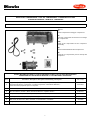
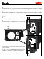
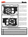
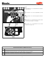
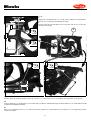
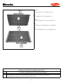
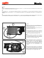
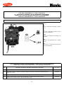
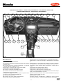
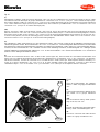
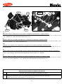
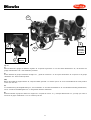
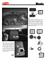
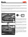
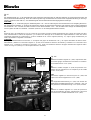
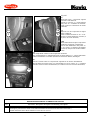
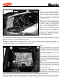
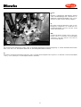
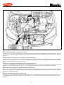
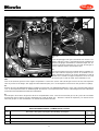
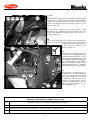
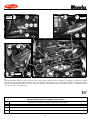
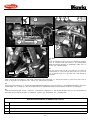
Fig.9C
(I)
Montare il gruppo climatizzatore “61“ sulla vettura nella medesima posizione occupata
originalmente
dal
gruppo
riscaldamento eliminato, inserendo la valvola ad espansione ed il condotto scarico
condensa rispettivamente attraverso il
foro rettangolare predisposto sul parafiamma ed il foro eseguito su gommino originale (vedi fig.7C). Fissare il gruppo
climatizzatore mediante elementi originali
conservati .
ATTENZIONE:
Non bloccare definitivamente la traversa
“T” di fissaggio gruppo climatizzatore
“61“ e di supporto cruscotto. Individuare
ed eliminare il connettore originale “X” (6
vie) dell’impianto elettrico della vettura e
sostituirlo con connettore fornito “111“
ed eseguire il collegamento al connettore
“110”, cablato all’impianto elettrico del
gruppo climatizzatore secondo le indicazioni di fig. 3C (vedi pos.9 dello schema
elettrico allegato).
ORIGINALE
ORIGINAL
ORIGINALI
ORIGINALS
T
ORIGINALI
ORIGINALS
61
(F)
Poser le groupe climatiseur "61" sur la voiture dans la même position du groupe réchauffeur éliminé et introduire la soupape à expansion et le tuyau de décharge eau
de condensation respectivément sur le trous rectangulaire disponible sur le pare-feu
et le trou percé sur le caoutchouc d’origine (voir fig. 7C). Fixer le groupe climatiseur
à l’aide des pièces de fixation d’origine gardées.
ATTENTION :
Ne serrez pas la traverse "T" de fixation groupe climatiseur "61" et de support tableau de bord. Eliminer le connecteur d’origine "X" (6 voies) du faisceau électrique de la
voiture et le remplacer par le connecteur fourni "111" à connecter au connecteur
"110" câblé au faisceau éLectrique du groupe climatiseur selon les indications de la
fig. 3C (voir pos. 9 du schéma électrique joint).
111
110
X
ELIMINARE
ELIMINER
DISCARD
ENTFERNEN
ELIMINAR
(GB)
Assemble the A/C unit "61" on the car in the same position of the discarded heater.
Insert the expansion valve and the condensate drainage hose on the rectangular hole
prepared on the firewall and on the hole drilled on the original rubber grommet (see
fig. 7C) respectively. Secure the A/C unit by means of the original fixing parts.
CAUTION :
Do not fix the transverse bar "T" which secures the A/C unit "61" and supports the
dashbaord. Discard the original connector "X" (6-way) of the car electric system and
replace it with the supplied connector "111". Effect the connection to the connector
"110", wired to the A/C unit electric system according to the indications of fig. 3C
(see pos. 9 of the enclosed wiring diagram).
40