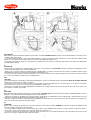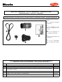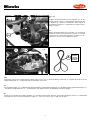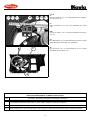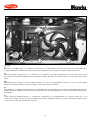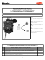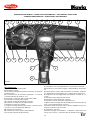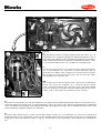
1
PEUGEOT 206
1.100i "EURO2"
(MOTORI/MOTEURS/ENGINES/DIE MOTORE/MOTORES) TU1JP/B-HDY(X)
1.400i "EURO2"
(MOTORI/MOTEURS/ENGINES/DIE MOTORE/MOTORES) TU3JP/B-KFY(X)
Con Servo Sterzo / Avec Direction Assistée
With Power Steering Mit Servolenkung
Con Servo
Codice/Code: 1PE13100E/1 + A03877
Istruzioni montaggio
condizionatore d’aria
Instructions pour monter le
conditionneur d’air
Air conditioning
installation instructions
Klimaanlage
Einbauanleitungen
Instrucciones para el montaje
del equipo aire acondicionado
DELPHI ITALIA AUTOMOTIVE SYSTEMS S.r.l. "Stabilimento Molinella"
Via Nobili, 2 40062 Molinella (Bologna) - Italy
Telefono (0039) 051.6906111 - Fax (0039) 051.6906287 - Email: [email protected]
PRESCRIZIONI PER IL MONTAGGIO DELL' IMPIANTO A/C DIAVIA OBBLIGATORIE PER IL TECNICO INSTALLATORE, IL QUALE, NEL CASO DI LORO INOSSERVANZA, SARA' DIRETTAMENTE ED ESCLUSIVAMENTE RESPONSABILE VERSO IL CLIENTE.
1. verificare il corretto serraggio della bulloneria fornita e rimossa e comunque di tutte le parti interessate al montaggio dell' impianto A/C;
2. verificare che non vi siano perdite d' acqua, olio e aria su motore, freni, servosterzo, servofreno, ecc.;
3. verificare tutti i livelli dei liquidi. Qualora venga rimosso il radiatore acqua, ricaricare nel circuito lo stesso liquido scarico e, se è necessario un rabbocco,
aggiungere il liquido anticongelante prescritto. Assicurarsi inoltre che lo spurgo aria sia fatto come prescritto dal costruttore;
4. accertarsi della giusta tensione di tutte le cinghie, e verificare lo stato di usura di quelle non sostituite;
5. verificare che non si abbiano interferenze critiche in qualunque condizione di funzionamento. In particolare accertarsi che siano garantite distanze di sicurezza fra tutti i particolari soggetti a movimento relativo.
6. garantirsi che non si abbiano fregamenti con conseguente usura tra le parti mediante un corretto serraggio e posizionamento delle stesse;
7. assicurarsi del corretto isolamento elettrico, della corretta installazione dei fusibili e di tutte le parti dell'impianto elettrico;
8. dopo aver effettuato la carica del refrigerante effettuare una accurata ricerca di eventuali perdite di gas;
9. eseguire comunque ogni operazione secondo norme di buona tecnica;
10. se durante l'operazione di installazione dell' impianto, vengono praticati fori o tagli, è obbligatorio proteggere tali parti con prodotto antiruggine.
PRESCRIPTIONS POUR LE MONTAGE DE L’EQUIPEMENT A/C DIAVIA A RESPECTER PAR LE TECHNICIEN INSTALLATEUR, CAR S’IL NE LES OBSERVAIT
PAS, IL SERAIT DIRECTEMENT ET EXCLUSIVEMENT RESPONSABLE EVERS LE CLIENT.
1. vérifier que la visserie fournie ou manipulée ainsi que toutes les parties concernées par le montage de l’équipement A/C sont serrées et fixées correctement;
2. vérifier qu’il n’y a pas des fuites d’eau, d’huile ou d’air sur le moteur, les freins, la servodirection, le servofrein, etc..;
3. vérifier tous les niveaux. Si un complément de liquide de refroidissement est à effectuer, utiliser le même liquide que celui qui est dans le circuit. Si le
circuit a été vidangé, faire le plein avec le liquide préconisé par le constructeur.
4. s’assurer que la tension des courroies est correcte et vérifier l’état d’usure de celles qui n’on pas été remplacées;
5. vérifier qu’il n’ y a pas d’interférence critique dans toutes les conditions de fonctionnement. S’assurer en particulier que les distances de sécurité entre
toutes les pièces sujettes à un mouvement relatif sont respectées;
6. s’assurer qu’il n’y a pas de frottement provoquant l’usure entre les parties à cause d’un défaut de serrage ou de positionnement de celles-ci;
7. s’assurer que l’isolation électrique, l’ installation des fusibles et de toutes les parties du faisceau électrique sont correctes;
8. après avoir realisé la charge du réfrigérant, effectuer une recherche minutieuse de fuite éventuelle de gaz;
9. de toute façon, effectuer toutes les opérations dans les régles de l’art;
10. si durant l’opération de mise en place de l’équipement des trous ou des coupes sont pratiquées, il est impératif de les protéger avec le produit antirouille.
INSTRUCTIONS FOR THE A/C SYSTEM FITTING TO BE FOLLOWED BY THE OPERATOR INSTALLING THE SYSTEM. IN CASE OF FAILURE TO COMPLY
WITH THEM, THE OPERATOR WILL BE DIRECTLY AND EXCLUSIVELY RESPONSIBLE TO THE CUSTOMER.
1. check the proper tightening of the supplied nuts and bolts and removal, and otherwise, of all parts involved in the assembly of the A/C system;
2. check that there are no water, oil or air leaks on the engine , brakes, power steering, power brakes, etc.;
3. check the level of all liquids. Should the water radiator be removed, refill the circuit with the same discharged liquid and, if it is necessary to top up ,
add the prescribed antifreeze liquid. Furthermore, make sure that the bleeding is carried out as prescribed by the manufacturer;
4. check the proper tension of all the belts and check the state of wear on those which have not been replaced;
5. check that there is no critical interference under any function condition. In particular check that the safety distances between all parts subject to relative
movement are guaranteed;
6. ensure that there is no rubbing between parts with consequent wear by means of proper tightening and positioning of the parts themselves;
7. check that electric insulation, fuse installation and all parts of the electric system are correct;
8. after the refrigerant charge, make a careful search for any gas leaks;
9. carry out all operations according to the rules of good technology;
10. should any holes or cuts be made during installation of the system, it is absolutely necessary to protect such parts with the rustpreventer.
VERBINDLICHE VORSCHRIFTTEN FÜR DEN EINBAUTECHNIKER BEI NICHTBEACHTUNG ERLISCHT JEDER ANSPRUCH AUF GARANTIE UND ERSATZTEILLIEFERUNG.
1. Jede DIAVIA-Klimaanlage ist gemäß der beigefügten Einbaueinleitung einzubauen;
2. Bei allen Einbauteilen der Klimaanlage ist auf die vorgeschriebene Anbringung an den vorgesehenen Punkten zu achten, ebenso auf die erforderliche Bewegungsfreiheit der einzelnen Aggregatteile.
3. Bei korrekter Positionierung und Befestigung der Teile sind Abnutzungen durch Reibung ausgeschlossen. Eventuell auftretende Störungen sind unverzüglich zu überprüfen;
4 . Alle Einbauteile, sowie die verwendeten Schrauben und Muttern sind auf ihre korrekte Spannung und festen Sitz hin zu überprüfen.
5. Alle Teile der elektrischen Anlage sowie die Sicherung sind auf Isolation und korrekte Installation hin zu überprüfen;
6. Nach Auffüllung der Klimaanlage mit dem Kältemittel muß die gesamte Anlage auf eventuelle Verluste von Gas überprüft werden;
7. Bei Inbetriebnahme der Klimaanlage ist die korrekte Spannung aller Keilriemen zu überprüfen. Nicht ersetzte Keilriemen sind auf ihre Abnutzung hin zu
untersuchen.
8. Nach Einbau der Klimaanlage ist zu überprüfen, daß Motor,Bremsen, Servolenkung und Servobremse keine Wasser-, Oel-,oder Luftverluste aufweisen;
9. Vor Übergabe des Wagens muß das Niveau aller Flüssigkeitsanzeigen überprüft werden. Falls beim Klimaanlageneinbau der Wasserkühler ausgebaut wurde, ist die entnommene Flüssigkeit im Umlauf wieder aufzufüllen und das erforderliche Frostschutzmittel nachzufüllen.
10. Im Falle, daß während der Installationsarbeiten der Anlage, Bohrungen oder Schnitte durchgeführt werden, ist es unbedingt notwendig, diese Teile mit
dem Rostschutzmittel zu schützen.
PRESCRIPCIONES PARA EL MONTAJE DE LA INSTALACIóN A/C OBLIGATORIAS PARA EL TECNICO INSTALADOR; EN CASO DE SUS INOBSERVANCIA,
ÉL SERÁ DIRECTAMENTE Y EXCLUSIVAMENTE RESPONSABLE HACIA EL CLIENTE.
1. verificad que los tornillos en dotación, los removidos y de todos modos todas las partes que se emplean para el montaje de la instalación A/C sean bien
apretadas;
2. verificad que no se producan pérdidas de agua, de aceite y de aire sobre el motor, los frenos, el servofreno, la servo dirección, etc;
3. verificad todos los niveles de los líquidos. En caso se remueva el radiador de agua, recargad en el circuito el mismo líquido descargado, y se es necesario
un relleno añadid el líquido anticongelamiento prescrito. Además, averiguad que el expurgo de aire sea hecho como está prescrito por el constructor;
4. averiguad que todas las correas sean bien tendidas y verificad el estado de desgaste de las que no han sido reemplazadas;
5. verificad que no se producan graves interferencias en cualquier condición de funcionamiento. En particular verificad de que sean garantizadas las distancias
de seguridad entre todos los elementos expuestos a movimiento relativo;
6. averiguad que no se producan fricaciones con consiguiente desgaste de las partes, apretándolas correctamente y poniendo esas mismas en posición correcta;
7. verificad el correcto aislamiento eléctrico, el correcto montaje de los fusibles y de todas las partes de la instalación eléctrica;
8. después de haber introducido el refrigerante, efectuad una busca diligente acerca de posibles pérdidas de gas;
9. de todos modos, efectuad cada operación según las normas de la mejor tecnología;
10. si durante la operación de puesta de la instalación se hacen agujeros o cortes les aconsejamos protejan estos puntos con un producto antioxido.
INDICE / INDEX / INDEX / INHALTSVERZEICHNIS / INDICE
Pag. / Page / Seite
NOTE DI MONTAGGIO
NOTES DE MONTAGE
FITTING NOTES
EINBAUANLEITUNGEN
NOTAS DE MONTAJE
4
TABELLA COPPIE DI SERRAGGIO
TABLEAU DES COUPLES DE SERRAGE
DRIVING TORQUES TABLE
TABELLE DER VERSCHRAUBUNSPAARE
TABLAS PARES DE TORSION
5
MONTAGGIO COMPRESSORE
POSE DU COMPRESSEUR
COMPRESSOR FITTING
KOMPRESSOREINBAU
MONTAJE COMPRESOR
7
MONTAGGIO CONDENSATORE-FILTRO ESSICCATORE
POSE DU CONDENSEUR-FILTRE DESHYDRATEUR
CONDENSER-RECEIVER DRIER FITTING
KONDENSATOR-TROCKNERFILTER EINBAU
MONTAJE CONDENSADOR- FILTRO SECADOR
13
MONTAGGIO COMPONENTI A.C. NELL’ABITACOLO
POSE DES COMPOSANTS A.C. DANS L’HABITACLE
A.C. COMPONENTS ASSEMBLY IN THE PASSENGER COMPARTMENT
EINBAU DER KLIMAANLAGEN-BESTANDTEILE IM WAGENINNEREN
MONTAJE COMPONENTES A.C. EN EL HABITACULO
27
COLLEGAMENTO TUBI GAS
INSTALLAZIONE COMPONENTI ELETTRICI NEL VANO MOTORE
RACCORDEMENT DES TUYAUX GAZ
INSTALLATION COMPOSANTS ELECTRIQUES DANS LE COMPARTIMENT MOTEUR
GAS PIPE CONNECTION
INSTALLATION OF ELECTRICAL COMPONENTS IN THE ENGINE COMPARTMENT
KAELTEMITTELSCHLAUCHVERBINDUNG
INSTALLATION DER ELEKTRISCHEN TEILE IM MOTORRAUM
CONEXION TUBOS GAS
INSTALACION COMPONENTES ELECTRICOS EN EL COMPARTIMENTO MOTOR
40
SCHEMA IMPIANTO ELETTRICO
SCHEMA DE L’INSTALLATION ELECTRIQUE
WIRING DIAGRAM
SCHEMA DER ELEKTRISCHEN ANLAGE
ESQUEMA INSTALLACION ELECTRICA
58
3
(I)
NOTE:
Lo schema di montaggio illustra l' impianto AC e comprende a volte dei componenti accessori (es. minimo veloce, radiatore, ecc.) che debbono
però essere ordinati separatamente, in aggiunta all' impianto base, consultando il ns. listino.
Tutte le indicazioni relative alla DESTRA ed alla SINISTRA sono riferite al senso di marcia: SINISTRA = lato guida, DESTRA = lato passeggero.
Tutti i numeri presenti nel testo e nelle figure, indicano componenti forniti del condizionatore e vanno pertanto riferiti ai kit di
figg.1A,1B,1.1B,1C,1D,1.1D.
Tutte le viti e i raccordi tubi gas vanno bloccati senza superare i valori massimi delle coppie di serraggio indicati nella tabella seguente, se non
diversamente specificato nel testo:
Per il corretto funzionamento ed affidabilità delle cinghie installate, eseguire le seguenti operazioni:
a) Avviare il motore con impianto AC inserito e dopo 15 minuti circa di funzionamento, ritensionare le cinghie.
b) La stessa operazione di tensionamento va ripetuta dopo 1500 Km dalla installazione dell'impianto AC.
Nella vettura provvista di dispositivi di sicurezza tipo AIR BAG o PROCON-TEN® lo smontaggio di tali componenti deve essere effettuato attenendosi
alle disposizioni delle rispettive case automobilistiche.
La quantità di gas R134a necessaria per la carica dell'impianto è di Kg. 0,700 (±0,025).
(F)
REMARQUE :
Le manuel d’instructions illustre l’équipement A/C et il comprend quelque fois des composants accessoires (par ex. : ralenti-accéléré, radiateur,
etc.) qui doivent cependant être commandés séparément, en plus de l’équipement de base, en consultant notre catalogue.
Toutes les indications de DROITE et de GAUCHE se réfèrent à la direction de marche : GAUCHE = côté conducteur, DROITE = côté passager.
Tous les numéros du texte et des figures indiquent les composants du conditionneur fourni.
ls doivent par conséquent être comparés aux kits
des fig.1A,1B,1.1B,1C,1D,1.1D.
Toutes les vis et les raccords des tuyaux gaz doivent être bloqués sans dépasser les valeurs maximales des couples de serrage indiqués dans le
tableau suivant, s’il n’y a pas de précision contraire.
Pour obtenir le bon fonctionnement et la fiabilité des courroies installées, effectuer les opérations suivantes :
a) Faire démarrer le moteur avec l’équipement d’air conditionné enclenché et après 15 minutes environ, tendre à nouveau les courroies.
b) Il faut répéter l’opération de tension de courroie 1500 Km après le montage de l’air conditionné.
Sur les voitures munies des systèmes de sécurité type AIR BAG ou PRECON-TEN®, le démontage de ces composants doit être effectué en suivant
scrupuleusement les dispositions de chaque Constructeur.
La quantité de gaz R134a nécessaire pour charger l’équipement est de Kg. 0,700 (±0,025).
(GB)
NOTE :
This instruction manual illustrates the A/C system and at times, includes accessories (ex.: idle-speed control, radiator, etc.). These parts, however,
must be ordered separately in addition to the basic kit according to our price list.
All references to RIGHT and LEFT hand are related to the driving direction : LEFT = driver’s side, RIGHT = passenger’s side.
All numbers quoted in the text and under the photos refer to the supplied componets of the air conditioning unit. One must therefore refer to the
kits shown in the figg.1A,1B,1.1B,1C,1D,1.1D.
All screws and gas pipes fittings must be locked without exceeding the maximum value of the driving torques indicated in the following table, if
not otherwise specified in the text.
Once fitting has been completed, spray an anticorrosive trasparent product on the installed metal parts.
To ensure functioning and reliability of installed belts, carry out the following procedures :
a) Start motor with A/C system switched on and after about 15 minutes adjust belt tension.
b) The same adjustment procedure should be repeated after 1500 Km from the installation of the A/C system.
In those vehicles with AIR-BAG or PRECON-TEN® safety devices, these components must be removed carefully following the instructions given by
the car manufacturers.
The quantity of R134a gas necessary for the system charge is Kg. 0,700 (±0,025).
(D)
ANMERKUNG:
Die Einbauanleitung beschreibt die Klimaanlage, in einigen Fällen gehören jedoch Bauteile hinzu (z.B. Leerlaufvorrichtung, Kühler, Lüfter usw.) die
separat zur Grundausstattung der Anlage zu bestellen sind, da es sich um Zusatzteile handelt, siehe unsere Preisliste. Alle Hinweise auf RECHTS
und LINKS beziehen sich auf die Fahrtrichtung: LINKS= Fahrerseite, RECHTS = Beifahrerseite.
Alle Ziffern im Text und der Abbildung 1A,1B,1.1B,1C,1D,1.1D beziehen sich auf vorhandene Bestandteile des Bausatzes.
Alle Schraub- und Schlauchverbindungen sind,falls nicht anders angegeben, gemäß unten stehender Tabelle anzuziehen .Nach beendetem Einbau
ist es ratsam auf die eingebauten Metallteile Schutzwachs aufzusprühen, um Rostbildungen zu verhindern. Für Funktions- und Lebensdauer der
Keilriemen ist folgendes zu beachten:
a) den Motor mit eingeschalteter Klimaanlage anlassen und nach ca. 15 Minuten der Funktion, die Riemen spannen.
b) Nach 1500 Km Riemen nachspannen.
Bei Fahrzeugen mit Sicherheitsvorrichtung wie AIR BAG oder PROCON-TEN® muß der Ausbau derselben, nur nach den Anleitungen der Automobilhäuser durchgeführt werden.
Die notwendige Menge des Gas R134a für die Auffüllung der Klimaanlage ist 0,700 (±0,025) Kg.
(E)
NOTAS:
El manual de instrucciones ilustra la instalación A.C. y a veces comprende componentes accesorios (por ejemplo: minimo acelerado, radiador, etc.)
que se deben ordenar separadamente, como agregado a la instalación base consultando nuesto listin.
Todas las indicaciones relativas a la DERECHA y a la IZQUIERDA se refieren al sentido de marcha: IZQUIERDA= lado conductor: DERECHA= lado
pasajero.
Todos los números presentes en el texto y en las figuras indican componentes abastecidos del equipo de aire acondicionado y se refieren a los kits
de las figuras 1A,1B,1.1B,1C,1D,1.1D.
Todos los tornillos y los racordes tubos gas tienen que ser bloqueados sin superar los valores máximos de las parejas de cerraje indicados por el
cuadro que sigue, si no diversamente especificado.
Una vez efectuado el montaje se aconseja aplicar en las paredes metálicas instaladas un producto spray transparente, de protección antioxidante.
Para la correcta puesta en marcha y fiabilidad de las correas montadas llevar a cabo las operaciones siguientes:
a) Arrancar el motor con el equipo de aire acondicionado conectado y después de 15 minudos de funcionamiento, volver a tensar las correas.
b) Hay que volver a repetir la misma operación de tensar la correa después de 1500 Kms. a partir del montaje del equipo.
En los coches provistos de dispositivos de seguridad modelo AIR BAG o PROCON-TEN® el desmontaje de estos componentes se debe efectuar
siguiendo las disposiciones de las respectivas casas automobilisticas.
La cantidad de gas R134a necesaria para cargar el equipo es de Kg. 0,700 (±0,025).
4
VALORI MASSIMI COPPIE DI SERRAGGIO PER VITI (in N.m)
VALEURS MAXIMUM DES COUPLES DE SERRAGE POUR LES VIS (en N.m)
MAXIMUM VALUES OF THE DRIVING TOURQUES FOR SCREWS (in N.m.)
MAXIMUMWERT DER VERSCHRAUBUNGEN FÜR DIE SCHRAUBEN (in N.m)
VALORES MAXIIMOS PAREJAS DE CERRAJE PARA TORNILLOS (en N.m)
Apertura in chiave (mm)
Ouverture en clef (mm)
Wrench opening (mm)
Schlüsselöffnung (mm)
Abertura en llave (mm)
Classe dell’acciaio della vite
Classe de l’acier de la vis
Screw steel class
Stahlklassifizierung der Schrauben
Clase del acero del tornillo
Filettatura
Filetage
Thread
Gewinde
Filetadura
5.8
8.8
10.9
M 4(x0.7)
1.8
2.9
4.2
M 5(x0.8)
3.4
5.5
7.5
8
M 6(x1)
6
10
13
10
M 7(x1)
11
16
21
11
M 8 (x1.25)
14
22
30
13
M 8x1
15
23
32
13
M10(x1.5)
27
45
61
17
M10 x1.25
31
50
67
17
M10 x1
33
53
71
17
M12 x1.5
51
78
105
19
M12 x1.25
60
94
125
19
M12 x1.75
84.8
119
143
19
M14 x1.5
80
120
165
22
M16 x1.5
120
185
255
24
M18 x1.5
165
265
350
27
M20 x1.5
225
360
490
30
M22 x1.5
295
480
640
32
M24 x2
390
610
805
36
RACCORDO
RACCORD
FITTINGS
VERBINDUNG
RACORDE
7
VALORI MASSIMI COPPIE DI SERRAGGIO
PER RACCORDI TUBI GAS (in N.m.)
VALEURS MAXIMUM DES COUPLES DE SERRAGE
POUR RACCORDS TUYAUX DU FREON (en N.m.)
MAXIMUM VALUES OF THE DRIVING TORQUES
FOR GAS PIPES FITTINGS (in N.m.)
MAXIMUMWERT DER VERSCHRAUBUNGSPAARE FÜR DIE
VERBINDUNGEN DER KÄLTEMITTELSCHLÄUCHE (in N.m.)
VALORES MAXMOS PAREJAS DE CERRAJE
PARA RACORDES TUBOS GAS (en N.m.)
5/8”
15.4÷17
3/4”
15.4÷17
7/8”
24.4÷27
1”
24.4÷27
- Lubrificare tutti i raccordi e gli O.R. con il nuovo olio refrigerante prima di collegarli
- Graisser tous les raccords et les O.R. avec le nuveau huile réfrigérant avant de les raccorder
- Lubricate all fittings and O-rings with new refrigerant oil
before connecting them
- Alle Verbindungsstücke und OR-Ringe vor deren Verbindung mit dem
neuen Kühlmittellöl ölen
- Lubrificar todos los empalmes y los O.R. con el nuevo aceite refrigerante antes de conectarlos
- Per avvitare a fondo o allentare i raccordi tubi gas usare due
chiavi per bilanciare coppia di torsione
- Pour visser à fond ou desserrer les raccords des tuyaux gaz,
utiliser le deux clés pour équilibrer le couple de torsion
- When tightening or loosening the fittings of the gas pipes, use
two wren- ches to equilize the torsion couple
- Um die Verbindungsstücke der Kältemittelschläuche gleichmäßig festzuschrauben oder zu lockern, zwei Schlüssel für das Verschraubungspaar verwenden
- Para enroscar a fondo o aflojar los empalmes tubos gas se deben usar dos
llaves para balancear el par de torsión
- Tagliare con utensile appropriato al materiale
- Couper à l’aide d’outil approprié
- Cut with a device suitable for the material
- Mit dem Material entsprechendem Werkzeug schneiden
- Cortar con herramienta apropiada al material
- Stagnare
- Étamer
- Tin
- Verzinnen
- Estañar
5
(I)
ATTENZIONE:
Nelle vetture dotate di marmitta catalitica è necessario controllare IN OGNI CASO la posizione di uscita dall'abitacolo del tubo scarico
condensa dell' evaporatore.
- Se il tubo dovesse risultare in prossimità della marmitta, in modo da essere investivo dalla fascia di calore emanata dalla marmitta
stessa, occorre tagliare il tubo subito dopo la sua uscita dall'abitacolo (riquadro "A").
- Se il tubo è provvisto di rompi-goccia (riquadro "B") bisogna bloccare il tubo ad elementi della vettura in posizione più distanziata
possibile dalla marmitta.
(F)
ATTENTION:
Sur les voitures munies de pot d’échappement à catalyse, il est nécessaire de TOUJOURS contrôler la position du dégorgement pour
condensat de l’évaporateur en sortie de l’habitacle.
- Dans le cas où le tuyau serait en proximité du pot d’échappement, ou dans la zone de trop forte chaleur, il faudrait couper le tuyau
immédiatement après le point de sortie de l’habitacle (illustration "A").
- Si le tuyau est muni de brise-gouttes (illustration "B"), il est nécessaire de le bloquer aux éléments de la voiture dans une position
qui est la plus lointaine possible du pot d’échappement.
(GB)
CAUTION:
The position where the evaporator condensate drainage hose comes out of the passenger compartment MUST BE ALWAIS CHECKED
whenever the vehicle has a catalytic converter.
- If the pipe is close enough to the converter to be heated by the heat generated by the converter itself, cut it down to just below
the point where it comes out of the passenger compartment (detail "A").
- If the pipe is provided with an anti-dripping device (detail "B"), the pipe must be secured to the vehicle at a point as far away from
the catalytic converter as possible.
(D)
ACHTUNG:
Bei Fahrzeugen mit Katalysator-Auspuff ist es notwendig, IN JEDEM FALL die Position des Kondenswasserabflußaustritts des Verdampfers am Austritt aus dem Fahrzeuginnenraum zu kontrollieren.
- Sollte der Schlauch in der Nähe des Auspuffs liegen, sodaß dieser im Hitzebereich des Auspuffs liegt, den Schlauch sofort am
Austritt aus dem Fahrzeuginnenraum abschneiden (Ausschnitt "A").
- Falls der Schlauch mit einer Tropfabdeckung ausgestattet ist (Ausschnitt "B"), den Schlauch so weit als möglich vom Auspuff verlegen und an Elemente des Fahrzeugs befestigen.
(E)
ATENCIÓN:
En los coches dotados de silenciador de escape catalítico es necesario controlar SIEMPRE la posición de salida del habitáculo del
tubo de drenaje condensación del evaporado.
- Si el tubo debiera resultar próximo al silenciador de escape y fuera embestido por la faja de calor que emana el silenciador mismo,
es necesario cortar el tubo después que sale del habitáculo (recuadro "A").
- Si el tubo está provisto de protección contra las gotas (recuadro "B") es necesario bloquear el tubo a elementos del coche en una
posición lo más lejos posible del silenciador del escape.
6
MONTAGGIO COMPRESSORE / POSE DU COMPRESSEUR / COMPRESSOR FITTING
KOMPRESSOREINBAU / MONTAJE COMPRESOR
MATERIALE FORNITO / MATERIEL FOURNI / SUPPLIED MATERIAL / GELIEFERTES MATERIAL / MATERIAL ABASTECIDO
Fig.1A
(I)
Vista componenti montaggio
compressore.
(F)
Vue des composants nécessaires au montage du compresseur.
1
4
(GB)
View of the components for
the compressor assembly.
5
3
(D)
Ansicht der Einbauteile des
Kompressors.
(E)
Vista de los componentes
para el montaje del compresor.
2
ELENCO MATERIALE FORNITO / LISTE DU MATERIEL FOURNI / LIST OF SUPPLIED MATERIALS
VERZEICHNIS DES GELIEFERTEN MATERIALS / LISTA MATERIAL ABASTECIDO
Pos.
Descrizione / Description / Description / Beschreibung / Descripción
Codice / Code
Kode / Codigo
1
Compressore / Compresseur / Compressor / Kompressor / Compresor
2
Piastra supporto compressore / Plaque support compresseur / Compressor support plate / Kompressorträger/
Placa soporte compresor
0011099/0
3
Puleggia galoppino / Poulie de renvoi / Idle pulley / Leitrollenriemenscheibe / Polea directriz
004052DV
4
Cinghia / Courroie / Belt / Riemen / Correa 6Kx1623
013558/0
5
Bulloneria / Boulonnerie / Nuts and bolts / Schraubensatz / Tornillería
037PE45
7
015179/0
OPERAZIONI PRELIMINARI / / OPERATIONS PRELIMINAIRES / PRELIMINARY OPERATIONS
VORBEREITUNGSARBEITEN / OPERACIONES PRELIMINARES
(I)
- Scollegare la batteria.
- Smontare la griglia presa aria posta superiormente alla mascherina frontale sede logo.
- Smontare la mascherina frontale sede logo.
- Smontare il gruppo fanali anteriori.
- Smontare il paraurti.
- Scollegare e sbloccare dalla propria sede il tiretto di chiusura cofano vano motore.
- Smontare il convogliatore aria completo di elettroventola, togliendo dalla propria sede il radiatore.
- Smontare la vaschetta di rabbocco liquido refrigerante, dal proprio supporto senza scollegare i tubi ad essa collegati.
- Smontare ed eliminare la cinghia di trasmissione (vedi fig. 2-3A).
(F)
- Débrancher la batterie.
- Déposer la grille de prise d’air placée partie supérieure de la plaque logo.
- Déposer la plaque logo.
- Déposer les blocs optiques avant.
- Déposer le pare-chocs.
- Débrancher le tirant de fermeture capot-moteur.
- Déposer l’ensemble convoyeur d’air et ventilateur en désolidarisant le radiateur de son logement.
- Désolidariser la cuve de nourrissage réfrigerant de son support sans déconnecter les tuyaux - raccordés à celle-ci.
- Eliminer la courroie de transmission (voir fig. 2-3A).
(GB)
- Disconnect the battery.
- Remove the air intake grille placed above the front logo mount.
- Remove the front logo mount.
- Remove the front headlight assy.
- Remove the bumper.
- Disconnet the hood fastener.
- Remove the air conveyor and associated fan by removing the radiator from its housing.
- Remove the refrigerant topping up tank from its support without disconnecting the hoses connected to it.
- Remove and discard the driving belt (see fig. 2-3A).
(D)
- Die Batterie abklemmen.
- Das Luftaufnahmegitter ober der Frontalblende des Markenzeichens ausbauen.
- Die Frontalblende des Markenzeichens ausbauen.
- Die vordere Scheinwerfergruppe ausbauen.
- Die Stosstange ausbauen.
- Die Zugstange der Motorhaubenverschliessung lösen und vom Gehäuse lockern.
- Die Luftführung mit dem Elektrolüfter ausbauen und den Kühler vom Gehäuse entfernen.
- Die Kühlerflüssigkeit-Nachfüllwanne von der Halterung ausbauen, ohne die daran angeschlossenen Schläuche abzuklemmen.
- Den Antriebsriemen ausbauen und entfernen (siehe Abb.2-3A).
(E)
- Desconectar la batería.
- Desmontar la rejilla toma de aire colocada en la parte superior de la placa porta mandos frontal del compartimiento del logotipo.
- Desmontar la placa porta mandos frontal del compartimiento del logotipo.
- Desmontar el grupo faros delanteros.
- Desmontar el parachoques.
- Desconectar y desbloquear de su alojamiento el tirante de cierre capó del compartimiento del motor.
- Desmontar el canalizador del aire completo de electroventilador, quitando de su compartimiento el radiador.
- Desmontar la vasca de llenado de líquido refrigerante, de su soporte sin desconectar los tubos a esa conectados.
- Desmontar y eliminar la correa de transmisión (véase fig. 2-3A).
8
Fig.2-3A
4
(I)
Togliere momentaneamente la vite originale "Vo" di fissaggio supporto motore, per permettere l’inserimento della cinghia "4" fornita in sostituzione della cinghia di
trasmissione originale "A". Posizionare la cinghia come indicato in figura.
(F)
Enlever momentanément la vis d’origine "Vo" de fixation
supérieure moteur pour introduire la courroie "4" fournie
à la place de la courroie de transmission d’origine "A". Positionner la courroie comme indiqué ci-contre.
Vo
4
Vo
A
ELIMINARE
ELIMINER
DISCARD
ENTFERNEN
ELIMINAR
(GB)
Temporarily remove the original engine support fixing screw "Vo" to allow the fitting of the belt "4" supplied in the place of the
original driving belt "A". Position the belt as indicated in the picture.
(D)
Die Originalschraube "Vo" zur Befestigung des Motorhalters vorübergehend entfernen, um die Einlegung des gelieferten Riemens "4"
- anstelle des Originalriemens "A" - zu ermöglichen. Den Riemen wie in der Abbildung ersichtlich anlegen.
(E)
Quitar por un momento los tornillos originales "Vo" de fijación del soporte del motor, para poder introducir la correa "4" suministrada
en sustitución de la correa de transmisión original "A". Colocar la correa como se indica en la figura.
9
a
b
FIG.4A
(I)
Vista dei fori filettati "a-b" del blocco motore, da utilizzare per il fissaggio della piastra di supporto compressore (2).
(F)
Vue des trous filétés "a-b" du bloc moteur à utiliser pour la fixation de la plaque compresseur (2).
(GB)
View of the engine block threaded holes "a-b" to be used for the compressor plate fixing (2).
(D)
Ansicht der Gewindebohrungen "a-b" am Motorblock für die Befestigung der Kompressorhalterplatte (2) zu verwenden.
(E)
Vista de los orificios fileteados "a-b" del bloque motor, que hay que utilizar para la fijación de la placa de soporte compresor (2).
10
2
b
a
b
10
6
a
10
9
1
6
11
3
10
7
FIG.5A
(I)
Rappresentazione schematico-riassuntiva dello staffaggio compressore con indicazione della relativa bulloneria di fissaggio.
10
8
(F)
Rèprèsentation schèmatique-rècapitulative des étriers compresseur avec indications de la boulonnerie de fixage correspondante.
(GB)
Recapitulatory diagram of the compressor bracketing and indications of the fixing nuts and bolts.
(D)
Schematische Gesamtdarstellung der Verbügelung des Kompressors, mit Hinweisen der entsprechenden Befestigungsschrauben und
-muttern.
(E)
Representación esquematica recopilativa del anclaje compresor, con indicaciones de la relativa tornilleria de ajuste.
BULLONERIA DA UTILIZZARE / BOULONNERIE A UTILISER / NUTS AND BOLTS TO BE USED
ZU BENUTZENDER SCHRAUBENSATZ / TORNILLERIA A UTILIZAR /
Pos.
Descrizione / Description / Description / Beschreibung / Descripción
6
Vite TE / Vis à tête à six pans / Hexagonal head screw / Sechskantschraube / Tornillo cabeza hexagonal M8x55
7
Vite TE / Vis à tête à six pans / Hexagonal head screw / Sechskantschraube / Tornillo cabeza hexagonal M8x95
8
Vite TE / Vis à tête à six pans / Hexagonal head screw / Sechskantschraube / Tornillo cabeza hexagonal M8x105
9
Vite TE / Vis à tête à six pans / Hexagonal head screw / Sechskantschraube / Tornillo cabeza hexagonal M10x45
10
Rondella piana / Rondelle plate / Plain washer / Flache U-Scheibe / Arandela llana φ 8
11
Rondella ondulata / Rondelle ondulée / Corrugated washer / Wellscheibe / Arandela ondulada φ 10
11
M
4
T
I
4
I
A
4
T
M
3
3
A
1
1
FIG.6A
(I)
Collegare la cinghia "4" come illustrato in figura e nello schema a lato.
SCHEMA GIRO CINGHIA:
M) Puleggia motore; I) Puleggia idroguida; T) Puleggia tendicinghia; A) Puleggia alternatore; 1) Elettropuleggia compressore;
3) Puleggia galoppino.
(F)
Raccorder la courroie "4" comme illustré sur la figure et sur le schéma ci-dessus.
SCHÉMA DU PARCOURS DE LA COURROIE:
M) Poulie moteur; I) Poulie direction assistée; T) Poulie de renvoi; A) Poulie alternateur; 1) Embrayage du compresseur;
3) Poulie de renvoi.
(GB)
Connect the belt "4" as illustrated in the picture and in the diagram.
BELT COURSE DIAGRAM:
M) Driving pulley; I) Power steering pulley; T) Guide pulley; A) Alternator pulley; 1) Compressor clutch; 3) Guide pulley.
(D)
Den Riemen "4" wie in der Abbildung und im Schema ersichtlich anlegen.
RIEMENUMLAUFSCHEMA:
M) Motorriemenscheibe; I) Servolenkungsriemenscheibe; T) Riemenspannerscheibe;
1) Kompressor-Elektroriemenscheibe; 3) Leitrollenriemenscheibe.
A)
Drehgeneratorriemenscheibe;
(E)
Conectar la correa "4" como se ilustra en la figura y en el esquema de al lado.
ESQUEMA TRAYECTORIA DE LA CORREA:
M) Polea motor; I) Polea de la servo dirección; T) Polea tensor de correa; A) Polea alternador; 1) Polea electromagnética del compresor; 3) Polea tensora.
12
MONTAGGIO CONDENSATORE - FILTRO ESSICCATORE / POSE DU CONDENSEUR - FILTRE DESHYDRATEUR
CONDENSER-RECEIVER FITTING / KONDENSATOR - TROCKNERFILTEREINBAU
MONTAJE CONDENSADOR - FILTRO SECADOR
MATERIALE FORNITO / MATERIEL FOURNI / SUPPLIED MATERIAL / GELIEFERTES MATERIAL / MATERIAL ABASTECIDO
31
Fig.1B
33
(I)
Vista componenti montaggio
condensatore.
(F)
Vue des composants nécessaires au montage du condenseur.
35
(GB)
View of the components for
the condenser assembly.
38
32
32
(D)
Ansicht der Einbauteile des
Kondensators.
34
37
36
(E)
Vista de los componentes para
el montaje del condensador.
39
ELENCO MATERIALE FORNITO / LISTE DU MATERIEL FOURNI / LIST OF SUPPLIED MATERIALS
VERZEICHNIS DES GELIEFERTEN MATERIALS / LISTA MATERIAL ABASTECIDO
Pos.
Descrizione / Description / Description / Beschreibung / Descripción
Codice / Code
Kode / Codigo
31
Condensatore / Condenseur / Condenser / Kondensator / Condensador
32
Staffa condensatore / Etrier condenseur / Condenseur bracket / Halterung Kondensator /
Abrazadera condensador
33
Elettroventola / Electroventilateur / Electric fan / Elektrogebläse / Electroventilador
34
Staffa di supporto elettroventola / Support électroventilateur / Electric fan support bracket /
Elektrogebläse-Haltebügel / Abrazadera de soporte electroventilador
0812288/0
35
Convogliatore aria / Convoyeur d’air / Air conveyor / Luftführung / Canalizador de aire
0361499/0
36
Sacchetto accessori / Sachet accessories / Bag of accessories / Säckchen mit Zubehörteilen /
Bolsita accesorios
0231399/1
37
Resistore / Résisteur / Resistor / Widerstand / Resistor
0681112/2
38
Protezione a spirale / Protection en spirale / Spiral protection / Spiralförmige Ummantelung /
Protección a espiral
070494/0
39
Fascetta / Collier / Clamp / Schelle / Banda
069715/0
13
022298OR/1
0812287/0
080151/0
MATERIALE FORNITO / MATERIEL FOURNI / SUPPLIED MATERIAL / GELIEFERTES MATERIAL / MATERIAL ABASTECIDO
Fig.1.1B
(I)
Vista componenti montaggio filtro essiccatore.
(F)
Vue des composants nécessaires au montage du filtre déshydrateur.
53
(GB)
View of the components for the receiver drier assembly.
(D)
Ansicht der Einbauteile des Trocknerfilters.
(E)
Vista de los componentes para el montaje del filtro secador.
52
51
ELENCO MATERIALE FORNITO / LISTE DU MATERIEL FOURNI / LIST OF SUPPLIED MATERIALS
VERZEICHNIS DES GELIEFERTEN MATERIALS / LISTA MATERIAL ABASTECIDO / LISTA DO MATERIAL FORNECIDO
Pos.
Descrizione / Description / Description / Beschreibung / Descripción
Codice / Code
Kode / Codigo
51
Staffa filtro / Etrier filtre / Receiver drier bracket / Filterbügel / Abrazadera filtro
52
Filtro essiccatore / Filtre déshydrateur / Receiver drier / Trocknerfilter / Filtro secador
017046/0
53
Pressostato / Pressostat / Pressure switch / Druckwächter / Presostato
043118/1
14
0361500/0
ASPORTARE
DETACHER
REMOVE
ENTFERNEN
QUITAR
F
E
ELIMINARE
ELIMINER
DISCARD
ENTFERNEN
ELIMINAR
C
CONSERVARE
GARDER
KEEP
AUFBEWAHREN
CONSERVAR
40mm
35mm
x
w
ASPORTARE
DETACHER
REMOVE
ENTFERNEN
QUITAR
ASPORTARE
DETACHER
REMOVE
ENTFERNEN
QUITAR
Fig.2B
(I)
Smontare ed eliminare dal convogliatore aria "C" l’elettroventola originale "E" (conservare i dadi di fissaggio). Asportare dal convogliatore aria le parti evidenziate "X" e "W" seguendo le indicazioni di figura. Asportare completamente la fusione "F" di supporto
elettroventola, tagliando lungo la linea evidenziata da tratteggio.
(F)
Eliminer le ventilateur d’origine "E" du convoyeur d’air "C" (garder les écrous de fixation). Désolidariser les parties "X" et "W" du
convoyeur d’air en suivant les indications de la figure. Eliminer la pièce moulée plastique "F" de support ventilateur en coupant suivant la ligne pointillée.
(GB)
Remove the original fan "E" from the air conveyor "C" (keep the fixing nuts). Remove the parts "X" and "W" from the air conveyor
according to the indications of the picture. Remove the fan support casting "F" by cutting along the dash lines.
15
Fig.2B
(D)
Den Originalelektrolüfter "E" von der Luftführung ausbauen und entfernen (die Befestigungsmuttern aufbewahren). Die gekennzeichneten Teile "X" und "W" - die Angaben der Abb. beachteten - von der Luftführung entfernen. Den Guss "F" zur Halterung des
Elektrolüfters entfernen, indem entlang der gekennzeichneten Schraffierung geschnitten wird.
(E)
Desmontar y eliminar del canalizador del aire "C" el electroventilador original "E" (conservar las tuercas de fijación). Quitar del canalizador de aire las piezas evidenciadas "X" y "W" siguiendo las indicaciones de la figura. Quitar completamente la unión "F" de
soporte del electroventilador, cortando a lo largo de la línea evidenciada por el pespunteo.
Fig.3B
(I)
Asportare dal convogliatore aria "C" le parti "J" e "Z" evidenziate nei particolari di figura, seguendo le indicazioni riportate.
ASPORTARE
DETACHER
REMOVE
ENTFERNEN
QUITAR
J
(F)
Désolidariser les parties "J" et "Z" du convoyeur d’air "C" comme ci-contre.
55 mm
15mm
C
20 mm
20mm
35mm 15mm
(GB)
Remove the parts "J" and "Z" from the air conveyor according to the indications of the picture.
(D)
Die Teile "J" und "Z" - im Detail der Abbildung gekennzeichnet - von der
Luftführung "C" entfernen und die angegebenen Hinweise beachten.
(E)
Quitar del canalizador de aire "C" las piezas "J" y "Z" evidenciadas en el
detalle de la figura, siguiendo las indicaciones indicadas.
16
Z
ASPORTARE
DETACHER
REMOVE
ENTFERNEN
QUITAR
Fig.4B
ORIGINALI
ORIGINALS
*
a
34
34.1 34.2
(I)
Posizionare l’elettroventola "33" sul convogliatore aria "C" come indicato in figura. Fissare la staffa di supporto "34"
all’elettroventola "33", utilizzando dadi
originali recuperati. Forare in opera φ6mm
sul convogliatore, in corrispondenza dei
punti "a" e fissarvi la staffa "34".
(F)
Positionner le ventilateur "33" sur le convoyeur d’air "C" comme indiqué sur la figure. Fixer le support "34" au ventilateur
"33" à l’aide des écrous d’origine. Percer
φ6mm sur le convoyeur en "a" et fixer
l’étrier "34".
a
34.1
ORIGINALI
ORIGINALS
34.2
*
33
a
C
34.3 34.4
(GB)
Position the fan "33" on the air conveyor
"C" as indicated in the picture. Secure the
support "34" to the fan "33" by means of
the original nuts. Drill φ6mm on the conveyor in the points "a" and secure the
bracket "34" .
(D)
Den Elektrolüfter "33" - wie in der Abbildung gekennzeichnet - an der Luftführung
"C" in Position bringen. Den Halterbügel
"34" mittels aufbewahrten Originalmuttern am Elektrolüfter "33" befestigen. In
Übereinstimmung mit den Punkten "a" an
der Luftführung Bohrungen von φ6mm
durchführen und den Bügel "34" befestigen.
C
33
34.4 34.3
(E)
Colocar el electroventilador "33" en el canalizador de aire "C" como se indica en la
figura. Fijar el soporte "34" en el electroventilador "33", utilizando las tuercas naturales recuperadas. Perforar durante el
trabajo φ6mm en el canalizador, en correspondencia con los puntos "a" y fijarlos
en el soporte "34".
a
ELEMENTI DI FISSAGGIO / PIECES DE FIXATION / FIXING PARTS / BEFESTIGUNGSELEMENTE / ELEMENTOS DE FIJACION
Pos.
Descrizione / Description / Description / Beschreibung / Descripción
*
Dado con rondella incorporata / Ecrou avec rondelle / Nut with washer / Mutter mit U-Scheibe / Tuerca con arandela M6
34.1
34.2
Vite TE / Vis à tête à six pans / Hexagonal head screw / Sechskantschraube / Tornillo cabeza hexagonal M6x16
Rondella piana / Rondelle plate / Plain washer / Flache U-Scheibe / Arandela llana φ6
34.3
Rondella piana / Rondelle plate / Plain washer / Flache U-Scheibe / Arandela llana φ6xφ18x2
34.4
Dado autobloccante / Ecrou autobloquant / Self-locking nut / Selbstsperrende Mutter / Tuerca autobloqueante M6
17
Fig.5B
34
37.1 37.2 37.3
37.3 37.2 37.1
(I)
Fissare il resistore "37", in corrispondenza dei fori predisposti sulla staffa "34".
(F)
Fixer la résistance "37" aux trous disponibles sur l’étrier
"34".
(GB)
Secure the resistor "37" to the holes prepared on the bracket "34".
(D)
Den Widerstand "37" in Übereinstimmung mit den vorhandenen Bohrungen am Bügel "34" befestigen.
37
(E)
Fijar el resistor "37", en correspondencia con los orificios
preparados en el soporte "34".
C
34
ELEMENTI DI FISSAGGIO / PIECES DE FIXATION / FIXING PARTS /
BEFESTIGUNGSELEMENTE / ELEMENTOS DE FIJACION
Pos.
Descrizione / Description / Description / Beschreibung / Descripción
37.1
Vite TCC / Vis à tête cylindrique avec calotte en forme de croix / Raised cheese head screw /
Linsen-Blechschraube mit Kreuzschlitz / Tornillo cabeza cilíndrica a forma de cruz M4x14
37.2
Rondella piana / Rondelle plate / Plain washer / Flache U-Scheibe / Arandela llana φ4
37.3
Dado autobloccante / Ecrou autobloquant / Self-locking nut / Selbstsperrende Mutter / Tuerca autobloqueante M4
18
Fig.6B
106 a
106
34
106 a
C
106 a
(I)
Sezionare dall’impianto elettrico
"106" (vedi fig.1D) il cablaggio
"106a", scollegando i connettori
evidenziati in figura.
Posizionare il cablaggio elettrico
"106a" come indicato in figura, e
collegarlo all’elettroventola "33" e
al resistore "37" (vedi pos. 34-35
dello schema elettrico allegato).
Bloccare il cablaggio in esame alla
staffa "34" mediante fascette a
strappo indicate da frecce in figura.
(F)
Désolidariser le câblage "106a" du
faisceau électrique "106" (voir fig.
1D) et débrancher les connecteurs
indiqués sur la figure.
Positionner le câblage "106a"
comme indiqué sur la figure et le
raccorder au ventilateur "33" et à
la résistance "37" (voir pos. 34-35
du schéma électrique joint). Fixer
le câblage à l’étrier "34" à l’aide
des colliers Velcro indiqués par les
flèches sur la figure.
(GB)
Remove the wiring "106a" from
the electric system "106" (see fig.
1D) by disconnecting the connectors indicated in the picture.
Position the electric wiring "106a"
as indicated in the picture and connect it to the fan "33" and to the
resistor "37" (see pos. 34-35 of
the enclosed wiring diagram). Secure the wiring to bracket "34" by
means of Velcro clamps indicated
by arrows in the picture.
37
106 a
(D)
Die Verkabelung "106a" von der elektrischen Anlage "106" (siehe Abb. 1D) trennen, indem die in der Abbildung gekennzeichneten
Steckverbinder getrennt werden. Die Elektroverkabelung "106a" , wie in der Abbildung ersichtlich, in Position bringen und an den
Elektrolüfter "33" und den Widerstand "37" (siehe Pos. 34-35 des beiliegenden Elektroschemas) anschliessen.Die Verkabelung mittels Abreisschellen, in der Abbildung mit Pfeilen gekennzeichnet, am Bügel "34" blockieren.
(E)
Seccionar de la instalación eléctrica "106" (véase fig. 1D) el cable "106a", desconectando los conectadores que están evidenciados
en la figura.Colocar el cable eléctrico "106a" como se indica en la figura, y conectarlo al electroventilador "33" y al resistor "37"
(véase pos. 34-35 del esquema eléctrico anexado). Bloquear el cable que se examina en el soporte "34" por medio de banda de
arrancar como se indica con las flechas en la figura.
19
Fig.7B
(I)
Eseguire sul convogliatore aria "C" i fori φ6,75mm in corrispondenza dei punti "b-c-d" seguendo le indicazioni di figura.
25mm
200mm
45mm
(F)
Percer les trous φ6,75mm sur le convoyeur d’air en "b-c-d" en suivant les
indications de la figure.
b
φ 6,75mm
C
25mm
φ 6,75mm
φ 6,75mm
d
13
0m
m
5mm
c
10mm
(GB)
Drill the holes φ6,75mm on the air conveyor "C" in the points "b-c-d" according to the indications of the picture.
(D)
Bohrungen von φ6,75mm in Übereinstimmung mit den Punkten "b-c-d" an der Luftführung "C" durchführen und die Angaben der
Abbildung beachten.
(E)
Efectuar en el canalizador de aire "C" los orificios φ6,75mm en correspondencia con los puntos "b-c-d-" siguiendo las indicaciones
de la figura.
20
C
39
39
Fig.8B
(I)
Inserire ad incastro le fascette fermacavo "39" sul convogliatore aria "C" in corrispondenza dei fori eseguiti.
(F)
Introduire les colliers "39" sur le convoyeur d’air "C" aux trous percés.
(GB)
Insert the clamps "39" on the air conveyor "C" in the holes previously drilled.
(D)
Die Schlauchhalterschellen "39" bis zum Einrasten an der Luftführung "C" in die ausgeführten Bohrungen einsetzen.
(E)
Introducir a encastre las abrazaderas de freno cable "39" en el canalizador de aire "C" en correspondencia con los orificios hechos.
21
Fig.9B
(I)
Fissare le staffe "32" al condensatore "31".
32
(F)
Fixer les étriers "32" au condenseur "31".
(GB)
Secure the brackets "32" to
the condenser "31".
31.1
(D)
Die Bügel "32" am Kondensator "31" befestigen.
(E)
Fijar las abrazaderas "32" en
el condensador "31".
31
31.1
32
ELEMENTI DI FISSAGGIO / PIECES DE FIXATION / FIXING PARTS /
BEFESTIGUNGSELEMENTE / ELEMENTOS DE FIJACION
Pos.
31.1
Descrizione / Description / Description / Beschreibung / Descripción
Vite autofilettante TCC / Vis autotaradeuse à tête cylindrique avec calotte en forme de croix /
Self-tapping raised cheese head screw / Selbstchneidende Linsen-Blechschraube mit Kreuzschnitz /
Tornillo autoenroscante cabeza clindrica a forma de cruz 4,2x9,5
22
31
φ
5mm
e
32.1 32.2 32.3
32
φ
5mm
e
32.1 32.2 32.3
C
Fig.10B
(I)
Posizionare il condensatore "31" sul convogliatore aria "C" come indicato in figura, in modo che risulti in battuta in corrispondenza
del lato evidenziato da frecce. Forare φ5mm sul convogliatore in corrispondenza dei punti "e", e fissare le staffe "32" di supporto
condensatore.
(F)
Positionner le condenseur "31" sur le convoyeur d’air "C" comme indiqué sur la figure de façon qu’il soit à battue sur le côté repéré
par les flèches.Percer φ5mm sur le convoyeur d’air en "e" et fixer les étriers condenseur "32" .
(GB)
Position the condenser "31" on the air conveyor "C" as indicated in the picture so that it is flush to the side indicated by arrows.Drill
φ5mm on the conveyor in the points "e" and secure the condenser brackets "32" .
(D)
Den Kondensator "31", wie in der Abbildung ersichtlich, an der Luftführung in Position bringen, sodass er sich im Anschlag mit dem
mit Pfeilen gekennzeichneten Rand befindet.Bohrungen von φ5mm in Übereinstimmung mit den Punkten "e" an der Luftführung durchführen und die Bügel "32" zur Kondensatorhalterung daran befestigen.
(E)
Colocar el condensador "31" en el canalizador de aire "C" como se indica en la figura, de manera que resulte a tope en correspondencia con el lado evidenciado por las flechas.Perforar φ5mm en el canalizador en correspondencia con los puntos "e", y fijar los
soportes "32" de soporte del condensador.
ELEMENTI DI FISSAGGIO / PIECES DE FIXATION / FIXING PARTS / BEFESTIGUNGSELEMENTE / ELEMENTOS DE FIJACION
Pos.
Descrizione / Description / Description / Beschreibung / Descripción
32.1
Vite TE / Vis à tête à six pans / Hexagonal head screw / Sechskantschraube / Tornillo cabeza hexagonal M5x16
32.2
Rondella piana / Rondelle plate / Plain washer / Flache U-Scheibe / Arandela llana φ5
32.3
Dado autobloccante / Ecrou autobloquant / Self-locking nut / Selbstsperrende Mutter / Tuerca autobloqueante M5
23
Fig.11B
53
115 mm
51
52
51
52
(F)
Introduire et serrer l’ensemble filtre déshydrateur "52" et pressostat "53" sur l’étrier "51" en
suivant les indications de la figure.
(GB)
Insert the dehydrator receiver "52" and associated pressure switch "53" on the bracket "51"
according to the indications of the picture.
(D)
Den Trockenfilter "52" komplet mit dem Druckwächter "53" am Bügel "51" einsetzen und
blockieren unddie Angaben der Abbildung beachten.
(E)
Introducir y bloquear el filtro secador "52" completo de presóstato "53" en el soporte "51"
siguiendo las indicaciones de la figura.
C
51.4 51.3 51.251.1
20mm
f
(I)
Inserire e bloccare il filtro essiccatore "52" completo di pressostato "53" sulla staffa "51",
seguendo le indicazioni di figura.
52
Fig.12B
(I)
Posizionare la staffa filtro "51" sul convogliatore aria "C" come visibile nel dettaglio di figura. Forare in opera φ6mm sul convogliatore
in corrispondenza dei punti "f" e procedere al fissaggio della staffa sul convogliatore.
(F)
Positionner l’étrier filtre "51" sur le convoyeur d’air "C" comme indiqué ci-dessus. Percer φ6mm sur le convoyeur en "f" et fixer
l’étrier sur le convoyeur.
ELEMENTI DI FISSAGGIO / PIECES DE FIXATION / FIXING PARTS / BEFESTIGUNGSELEMENTE / ELEMENTOS DE FIJACION
Pos.
Descrizione / Description / Description / Beschreibung / Descripción
51.1
Vite TE / Vis à tête à six pans / Hexagonal head screw / Sechskantschraube / Tornillo cabeza hexagonal M6x16
51.2
Rondella piana / Rondelle plate / Plain washer / Flache U-Scheibe / Arandela llana φ6
51.3
Rondella piana / Rondelle plate / Plain washer / Flache U-Scheibe / Arandela llana φ6x φ18x2
51.4
Dado autobloccante / Ecrou autobloquant / Self-locking nut / Selbstsperrende Mutter / Tuerca autobloqueante M6
24
Fig.12B
(GB)
Position the dehydrator receiver bracket "51" on the air conveyor "C" as shown in the picture. Drill φ6mm on the conveyor in the
points "f" and secure the bracket to the conveyor.
(D)
Den Filterbügel "51" , wie im Detail der Abbildung ersichtlich, an der Luftführung "C" in Position bringen. Bohrungen von φ6mm in
Übereinstimmung mit den Punkten "f" an der Luftführung durchführen und die Befestigung des Bügels an der Luftführung durchführen.
(E)
Colocar el soporte del filtro "51" en el canalizador de aire "C" como se ve en el detalle de la figura. Perforar durante el trabajo φ6mm
en el canalizador en correspondencia con los puntos "f" y proceder a la fijación del soporte en el canalizador.
Fig.13B
31
13/32"
CC
38
31
13/32"
CC
(I)
Inserire il tubo gas 13/32"CC attraverso il foro predisposto sul convogliatore aria "35". Applicare sul
tubo gas in esame per il tratto indicato in figura la
protezione a spirale "38". Collegare il tubo gas al
condensatore "31". Fissare il convogliatore aria al
condensatore come indicato in figura .
(F)
Introduire le tuyau gaz 13/32"CC sur le trou disponible sur le convoyeur d’air "35". Appliquer la protection spiralée "38" sur le tuyau gaz dans la zone
indiquée sur la figure. Raccorder le tuyau gaz au
condenseur "31". Fixer le convoyeur d’air au condenseur comme indiqué sur la figure.
(GB)
Insert the 13/32"CC gas hose in the hole prepared
on the air conveyor "35". Apply the spiral screen
"38" on the area indicated in the picture. Connect
the gas hose to the condenser "31". Secure the air
conveyor to the condenser as indicated in the picture.
35
(D)
Den Kältemittelschlauch 13/32"CC durch die
vorhandene Öffnung an der Luftführung "35" einführen. Die spiralenförmige Ummantelung "38"
am gekennzeichneten Teil des Kältemittelschlauches anlegen. Den Kältemittelschlauch am Kondensator "31" anschliessen. Die Luftführung, wie
in der Abbillung sichtbar, am Kondensator befestigen.
35.1
13/32"
CC
(E)
Introducir el tubo del gas 13/32" CC a través del
orificio preparado en el canalizador del aire "35".
Colocar en el tubo del gas que se está examinando, en el trecho indicado la protección de espiral
"38". Conectar el tubo del gas al condensador
"31". Fijar el canalizador de aire en el condensador
como se indica en la figura.
ELEMENTI DI FISSAGGIO / PIECES DE FIXATION / FIXING PARTS / BEFESTIGUNGSELEMENTE / ELEMENTOS DE FIJACION
Pos.
35.1
Descrizione / Description / Description / Beschreibung / Descripción
Vite autofilettante TE / Vis autotaradeuse à tête à six pans / Self-tapping hexagonal head screw /
Selbstschneidende Sechskantschraube / Tornillo autoenroscante cabeza hexagonal 4,2x13
25
13/32"
CC
52
31
C
33
FIG.14B
(I)
Rimontare il convogliatore aria "C", completo di: condensatore "31", elettroventola "33" e filtro essiccatore "52", sulla vettura come
in origine. Reinserire il radiatore nelle proprie sedi inferiori. Ricollegare il tiretto al gancio di chiusura cofano vano motore.
(F)
Reposer l‘ensemble convoyeur d’air "C", condenseur "31", ventilateur "33" et filtre déshydrateur "52" sur la voiture dans sa position. Introduire de nouveau le radiateur dans ses logements inférieurs. Raccorder de nouveau le tirant au crochet de fermeture capotmoteur.
GB)
Reassemble the air conveyor "C" and associated condenser "31", fan "33" and dehydrator receiver "52" on the car in the original
position. Fit again the radiator in its lower housings. Connect again the hood fastener.
(D)
Die Luftführung "C" komplett mit Kondensator "3", Elektrolüfter "33" und Trockenfilter "52" wieder in die Originalposition des Fahrzeuges einbauen. Den Kühler wieder in der unteren Position einsetzen. Die Zugstange wieder mit dem Verschlusshaken der Motorhaube verbinden.
(E)
Volver a montar el canalizador de aire "C", completo de: condensador "31", electroventilador "33" y el filtro secador "52", en el
coche como en origen. Volver a introducir el radiador en sus propios alojamientos inferiores. Conectar nuevamente el tirante al gancho de cierre del capó del compartimiento del motor.
26
MONTAGGIO COMPONENTI A.C. NELL’ABITACOLO
POSE DES COMPOSANTS A.C. DANS L’HABITACLE
A.C. COMPONENTS ASSEMBLY IN THE PASSENGER COMPARTMENT
EINBAU DER KLIMAANLAGEN-BESTANDTEILE IM WAGENINNEREN
MONTAJE COMPONENTES A.C. EN EL HABITACULO
MATERIALE FORNITO / MATERIEL FOURNI / SUPPLIED MATERIAL / GELIEFERTES MATERIAL / MATERIAL ABASTECIDO
Fig.1C
(I)
Vista componenti montaggio evaporatore.
64
(F)
Vue des composant nécessaire au montage de l’évaporateur.
(GB)
View of the evaporator assembly components.
62
(D)
Ansicht der Einbauteile des Verdampfers.
63
(E)
Vista de los componentes para el montaje del evaporador.
61
ELENCO MATERIALE FORNITO / LISTE DU MATERIEL FOURNI / LIST OF SUPPLIED MATERIALS
VERZEICHNIS DES GELIEFERTEN MATERIALS / LISTA MATERIAL ABASTECIDO
Pos.
Descrizione / Dèscription / Description / Beschreibung / Descripción
Codice / Code
Kode / Codigo
61
Gruppo climatizzatore / Groupe climatiseur / Climate control unit / Heizklimagerät / Grupo climatizador
0301029/1
62
Sacchetto accessori / Sachet accessoires / Bag of accessories / Säckchen mit Zuberhörteilen /
Bolsita accesorios
029595/0
63
Flangia tubi gas / Bride tuyaux gaz / Gas pipe flange / Kältemittelschlauchflansch / Brida tubos gas
043061/1
64
Mastice anticondensa / Mastic anti-condensation / Condensation-proofing material /
Kondenserwasserdichtemasse / Masilla anticondensación
039055/0
27
OPERAZIONI PRELIMINARI / OPERATIONS PRELIMINAIRES / PRELIMINARY OPERATIONS
VORBEREITUNGSARBEITEN / OPERACIONES PRELIMINARES
D
Z
G
A
B
V
E
C
C
O
N
D
Q
R
I
M
L
L
S
Z
P
T
F
U
G
H
Fig.2C
(I)
NELL’ABITACOLO:
A) Smontare AIR BAG® lato guida.
B) Smontare il volante.
C) Smontare il semiguscio superiore ed inferiore di copertura
piantone sterzo.
D) Smontare la leva di comando tergicristallo , e la leva di
comando indicatori di direzione - luci.
E) Smontare il coperchio della scatola porta fusibili.
F) Smontare il cassetto porta-oggetti.
G) Smontare i fianchetti laterali del cruscotto.
H) Smontare il tunnel freno di stazionamento.
I) Sollevare la cuffia leva cambio.
L) Togliere i fissaggi del tunnel leva cambio e spostare il tunnel verso la zona posteriore dell’abitacolo
M) Smontare il posacenere.
N) Smontare la cornice quadro strumentazione.
O) Smontare il quadro strumentazione.
P) Smontare il vano di predisposizione o se presente l’autoradio.
Q) Smontare la cornice dell’ orologio e dell’interruttore di emergenza.
R) Smmontare la cornice della mascherina di comando: ventilazione, distribuzione e miscelazione aria; completa di bocchette aria.
S) Togliere le viti di fissaggio della mascherina di comando al cruscotto.
T) Smontare la bocchetta laterale destra.
U) Smontare la parte destra del cruscotto.
V) Smontare la sede dispositivo regolazione fari.
Togliere le viti di fissaggio alla vettura della barra trasversale di supporto, posta internamente al cruscotto.
Spostare la barra trasversale verso l’interno dell’abitacolo per permettere la rimozione del cruscotto.
Z) Smontare il cruscotto.
Smontare il gruppo riscaldamento, scollegando i manicotti acqua
sul lato vano motore, conservare tutti gli elementi di fissaggio.
28
Fig.2C
(F)
DANS L’HABITACLE:
A) Déposer l’AIR BAG côté conduite.
B) Déposer le volant.
C) Déposer la demie-enveloppe supérieure et inférieure de la colonne de direction.
D) Déposer le levier de commande essuie-glace et le levier de commande feux de direction-blocs optiques.
E) Déposer le couvercle de la boîte à fusibles.
F) Déposer la boîte à gants.
G) Déposer les panneuax latéraux du tableau de bord.
H) Déposer le tunnel du levier frein de stationnement.
I) Soulever le soufflet du levier de changement de vitesse
L) Désolidariser les pièces de fixation tunnel levier de changement de vitesse et déplacer le tunnel vers l’ arrière de l‘habitacle.
M) Déposer le cendrier.
N) Déposer le cadre du tableau de bord.
O) Déposer le tableau de bord.
P) Déposer le logement autoradio ou l’autoradio, si présent.
Q) Déposer le cadre de l’horloge et de l’interrupteur de secours.
R) Déposer le cadre de la plaque des commandes ventilation, distribution, mélange d’air et les prises air.
S) Eliminer les vis de fixation de la plaque des commandes au tableaud e bord.
T) Déposer la prise air latérale droite.
U) Déposer la partie droite du tableau de bord.
V) Déposer le logement du dispositif de réglage feux.
Eliminer les vis de fixation à la voiture de la barre transversale de support placée à l’intérieur du tableau de bord.
Déplacer la barre transversale vers l’intérieur de l’habitacle pour permettre la dépose du tableau de bord.
Z) Déposer le tableau de bord.
Déposer le réchauffeur en déconnectant les manchons de l’eau sur le côté logement moteur, garder toutes les pièces de fixation.
(GB)
IN THE PASSENGER COMPARTMENT :
A) Remove the AIR BAG on driver’s side.
B) Remove the steering wheel.
C) Remove the steering column upper and lower half-envelopes.
D) Remove the windscreen wiper control lever and the turn indicators-headlights control.
E) Remove the cover of the fuse box.
F) Remove the glove box.
G) Remove the dashboard side panels.
H) Remove the parking brake tunnel.
I) Lift the gear lever guard.
L) Remove the gear lever tunnel fixings and move the tunnel to the passenger compartment rear area.
M) Remove the ash-tray.
N) Remove the cluster frame.
O) Remove the cluster
P) Remove the prepared car radio housing or the car radio if present.
Q) Remove the clock and emergency switch frame.
R) Remove the ventilation, distribution and air mixing controls mount frame and associated air inlet grilles.
S) Remove the control mount fixing screws to the dashboard.
T) Remove the right side air inlet grille.
U) Remove the dashboard right part.
V) Remove the headlights adjusting device housing.
Remove the transverse bar fixing screws to the car placed inside the dashboard.
Move the transverse bar towards the passenger compartment inside to allow the dashboard removal.
Z) Remove the dashboard.Remove the heater by disconnecting the water sleeves on engine compartment side.
Keep all the fixing parts.
29
Fig.2C
(D)
IM FAHRZEUGINNEREN:
A) Den Lenker-AIR-BAG ausbauen.
B) Das Lenkrad ausbauen.
C) Das obere und untere Halbgehäuse zur Lenksäulenabdeckung ausbauen.
D) Den Scheibenwischerhebel und den Fahrtrichtungsanzeiger-Licht-Hebel ausbauen.
E) Den Deckel der Sicherungsdose ausbauen.
F) Den Handschuhkasten ausbauen.
G) Die Seitenteile des Armaturenbrettes ausbauen.
H) Den Tunnel der Handbremse ausbauen.
I) Die Schutzhaube des Ganghebels anheben.
L) Die Befestigungen des Ganghebel-Tunnels entfernen und den Tunnel in die obere Zone des Fahrzeuges verlegen.
M) Den Aschenbecher ausbauen.
N) Den Rahmen der Instrumentenfafel ausbauen.
O) Die Instrumententafel ausbauen.
P) Das vorbereitete Gehäuse oder wenn vorhanden , das Autoradio ausbauen.
Q) Den Rahmen der Uhr und des Alarmblinker-Schalters ausbauen.
R) Den Rahmen der Blende zur Steuerung der: Lüftung, Verteilung und Luftmischung, komplet mit Lufteinlassgitter, ausbauen.
S) Die Befestigungsschrauben der Steuerblende am Armaturenbrett ausbauen.
T) Das seitliche rechte Einlassgitter ausbauen.
U) Den rechten Teil des Armaturenbrettes ausbauen.
V) Das Gehäuse der Lichtregelungsvorrichtung ausbauen.
Die Befestigungsschrauben am Fahrzeug des Querträgers zur Halterung, im Inneren des Armaturenbrettes, entfernen.
Den Querträger ins Fahrzeuginnere verlegen, um die Entfernung des Armaturenbrettes zu erleichtern.
Z) Das Armaturenbrett ausbauen.
Die Heizungsgruppe ausbauen, indem die Wasserschläuche an der Motorraumseite abgeklemmt werden, alle Befestigungssteile aufbewahren.
(E)
EN EL HABITÁCULO:
A) Desmontar la bolsa neumática del lado del conductor.
B) Desmontar el volante.
C) Desmontar la semienvoltura superior e inferior de protección de la columna de dirección.
D) Desmontar la palanca de mando de limpiaparabrisas, y la palanca de mando de los indicadores de dirección – luces.
E) Desmontar la tapa de la caja del porta fusibles.
F) Desmontar la caja del portaguantes.
G) Desmontar las protecciones laterales del tablero de instrucciones.
H) Desmontar el túnel del freno de aparcamiento.
I) Levantar la protección de la palanca de cambio.
L) Quitar las fijaciones del túnel de la palanca de cambio y mover el túnel hacia la zona posterior del habitáculo.
M) Desmontar el cenicero.
N) Desmontar el marco del cuadro de los instrumentos.
O) Desmontar el cuadro de instrumentos.
P) Desmontar el compartimiento de preparación de la radio si hay.
Q) Desmontar el marco del reloj y del interruptor de emergencia.
R) Desmontar el marco de la placa porta mandos + mandos: ventilación, distribución y mezcla del aire; completa de bocas de entrada
del aire.
S) Quitar los tornillos de fijación de la placa porta mandos del tablero de instrucciones.
T) Desmontar la boca lateral derecha.
U) Desmontar la parte derecha del tablero de instrucciones.
V) Desmontar el alojamiento del dispositivo de regulación de los faros.
Quitar al vehículo los tornillos de fijación de la barra transversal de soporte, colocada en el interior del tablero de instrucciones.
Mover la barra transversal hacia el interior del habitáculo para poder quitar el tablero de instrucciones.
Z) Desmontar el tablero de instrucciones.
Desmontar el grupo de calefacción, desconectando los manguitos del agua en el lado del compartimiento del motor, conservar todos
los elementos de fijación.
30
61
112
106 b
109
110
112
111
106
106 b
Fig.3C
(I)
Sezionare dall’impianto elettrico "106" il cablaggio "106b" (vedi fig.1D), scollegando i connettori evidenziati in figura. Cablare ai
cavi dell’impianto elettrico del gruppo climatizzatore i connettori "110" e "111" (vedi pos. 7-9 dello schema elettrico allegato). Collegare al connettore "111" il cablaggio elettrico "106b" (vedi pos. 8 dello schema elettrico allegato) e posizionarlo sul gruppo climatizzatore "61" come visibile in figura (vedi anche figura seguente). Collegare il cavo elettrico "GIALLO-ROSSO" "112" al connettore
"110" e al connettore "111" (vedi pos. 6 dello schema elettrico allegato).
31
Fig.3C
(F)
Désolidariser le câblage "106b" du faisceau électrique "106" (voir fig. 1D) et débrancher les connecteurs indiqués ci-dessus. Câbler
aux câbles du faisceau électrique du groupe climatiseur les connecteurs "110" et "111" (voir pos. 7-9 du schéma électrique joint).
Raccorder le câblage "106b" au connecteur "111" (voir pos. 8 du schéma électrique joint) et le positionner sur le groupe climatiseur
"61" comme visible sur la figure (voir la figure suivante aussi). Raccorder le fil "JAUNE-ROUGE" "112" au connecteur "110" et au
connecteur "111" (voir pos. 6 du schéma électrique joint).
(GB)
Remove the wiring "106b" from the electric system "106" (see fig. 1D) by disconnecting the connectors indicated in the picture.
Wire the connectors "110" and "111" to the A/C unit electric system cables (see pos. 7-9 of the enclosed wiring diagram). Connect
the electric wiring "106b" to the connector "111" (see pos. 8 of the enclosed wiring diagram) and position it on the A/C unit "61"
as shown in the picture (see also the following picture). Connect the "YELLOW-RED" electric cable "112" to the connector "110"
and to the connector "111" (see pos. 6 of the enclosed wiring diagram).
(D)
Die Verkabelung "106b" (siehe Abb.1D) von der elektrischen Anlage "106" trennen, indem die in der Abbildung ersichtlichen Steckverbinder getrennt werden. Die Steckverbinder "110" und "111" (siehe Pos. 7-9 des beiliegenden Elektroschemas) mit den Kabeln
der elektrischen Anlage des Heizklimagerätes verkabeln. Die elektrische Verkabelung "106b" (siehe Pos. 8 des beiliegenden Elektroschemas) mit dem Steckverbinder "111" verbinden und wie in der Abbildung ersichtlich, am Klimaheizgerät "61" anbringen ( siehe
folgende Abbildung). Den Elektrokabel "GELB-ROT" "112" an den Steckverbinder "110" und den Steckverbinder "111" anschliessen
(siehe Pos.6 des beiliegenden Elektroschemas).
(E)
Seccionar de la instalación eléctrica "106" el cable "106b" (véase figura 1D), desconectando los conectadores evidenciados en la
figura. Unir a los cables de la instalación eléctrica del grupo climatización los conectadores "110" y "111" (véase pos. 7-9 del esquema eléctrico anexado). Conectar al conectador "111" el cable eléctrico "106b" (véase pos. 8 del esquema eléctrico anexado) y colocarlo en el grupo climatización "61" como se ve en la figura (también véase figura siguiente). Conectar el cable eléctrico
"AMARILLO–ROJO" "112" al conectador "110" y al conectador "111" (véase pos. 6 del esquema eléctrico anexado).
Fig.4C
61
(I)
Vista del posizionamento del cablaggio
elettrico "106b" sul gruppo climatizzatore
"61".
(F)
Vue du positionnement du câblage électrique "106b" sur le groupe climatiseur
"61".
(GB)
View of the electric wiring "106b" positioning on the A/C unit "61".
(D)
Ansicht der Anbringung der Elektroverkabelung "106b" am Heizklimagerät "61".
(E)
Vista de la colocación del cable eléctrico
"106b" en el grupo climatización "61".
106 b
106 b
32
106 b
ORIGINALE
ORIGINAL
61
S
a
119
117
106 b
118
106 b
Fig.5C
(I)
Operazione valida per modelli vetture che prevedono l’installazione di compressore a cilindrata variabile.
Sfilare la sonda "S" dalla propria sede fissarla in corrispondenza dei fori "a" presenti sul gruppo climatizzatore "61" mediante fascette
"118". Sigillare il foro della sede sonda mediante tappo "117".
(F)
Opération valide pour les modèles disponibles pour l’installation du compresseur à cylindrée variable.
Retirer la sonde "S" de son logement et la fixer aux trous "a" disponibles sur le groupe climatiseur "61" à l’aide des colliers "118".
Introduire l’obturateur "117" dans le logement sonde.
(GB)
Operation to be effected on car models which are prepared for the variable displacement compressor fitting.
Remove the probe "S" and secure it to the holes "a" present on the A/C unit "61" by means of clamps "118". Insert the cap "117"
on the probe hole.
(D)
Gültiger Arbeitsvorgang bei Fahrzeigmodellen für die der Einbau eines Kompressors mit veränderlichen Hubraum vorgesehen ist.
Den Fühler "S" aus dem Gehäuse herausziehen und in Übereinstimmung mit den Bohrungen "a" am Heizklimagerät "61" mittels
Schelle "118" befestigen. Die Öffnung des Fühlergehäuses mit dem Stopfen"117" abdichten.
(E)
Operación válida para modelos de vehículos que prevén la instalación del compresor de cilindrada variable.
Extraer la sonda "S" de su proprio alojamiento fijarla en correspondencia con los orificios "a" que se hallan en el grupo de climatización "61" por medio de abrazaderas "118". Sellar el orificio del alojamiento por medio de tapa "117".
ELEMENTI DI FISSAGGIO / PIECES DE FIXATION / FIXING PARTS /
BEFESTIGUNGSELEMENTE / ELEMENTOS DE FIJACION
Pos.
119
Descrizione / Description / Description / Beschreibung / Descripción
Vite autofilettante TCC / Vis autotaradeuse à tête cylindrique avec calotte en forme de croix /
Self-tapping raised cheese head screw/Selbstchneidende Linsen-Blechschraube mit Kreuzschnitz /
Tornillo autoenroscante cabeza clindrica a forma de cruz 4x10
33
61
G
R
ELIMINARE
ELIMINER
DISCARD
ENTFERNEN
ELIMINAR
G
ORIGINALE
ORIGINAL
D
D
ORIGINALE
ORIGINAL
Fig.6C
(I)
Prima di eliminare il gruppo riscaldatore originale "R" recuperare il gommino "G" e il blocchetto distanziatore "D", da rimontare sul
gruppo climatizzatore "61" nella medesima posizione.
(F)
Avant d’éliminer le groupe réchauffeur d’origine "R", garder le caoutchouc "G" et la pièce intercalaire "D" à reposer sur le groupe
climatiseur "61" dans la même position.
(GB)
Before discarding the original heater "R", keep the rubber grommet "G" and the spacer "D" to be reassembled in the same position
on the A/C unit "61".
(D)
Vor der Entfernung der Originalheizung "R", die Gummitülle "G" und den Abstandsblock "D" zur Wiederverwendung aufbewahren,
um sie wieder am Heizklimagerät "61" in der gleichen Position einzubauen.
(E)
Antes de eliminar el grupo de calefacción original "R" recuperar el caucho "G" y el bloque distanciador "D", que hay que volver a
montar en el grupo climatización "61" en la misma posición.
34
ELIMINARE
ELIMINER
DISCARD
ENTFERNEN
ELIMINAR
A
Fig.7C
(I)
Eliminare l’imbottitura pretranciata e il sottostante gommino in corrispondeza del foro rettangolare predisposto sul parafiamma per la fuoriuscita
della valvola d’espansione del gruppo climatizzatore (zona A). Eliminare l’imbottitura pretranciata
e conservare il gommino sottostante "W" (zona
B). Eseguire il forare φ22mm nel centro del gommino in esame, quindi reinserirlo nella propria
sede originale.
ELIMINARE
ELIMINER
DISCARD
ENTFERNEN
ELIMINAR
CONSERVARE
GARDER
KEEP
AUFBEWAHREN
CONSERVAR
B
(F)
Eliminer l’embourrure prédécoupée
et le caoutchouc situé au-dessous
au niveau du trou rectangulaire disponible sur le pare-feu pour la sortie de la soupape à expansion du
groupe climatiseur (zone A). Eliminer l’embourrure prédécoupée et
garder le caoutchouc situé au-dessous "W" (zone B). Percer φ22mm
au centre du caoutchouc et ensuite
le introduire de nouveau dans son
logement d’origine.
B
W
W
φ22mm
35
Fig.7C
(GB)
Discard the pre-shorn padding and the rubber grommet situated below over the rectangular hole prepared on the firewall for the A/
C unit expansion valve coming out (area A). Discard the pre-shorn padding and keep the rubber grommet "W" situated below (area
B). Drill φ22mm in the center of the rubber grommet and then insert it again on its original housing.
(D)
Die vorgeschnittene Polsterung und die darunter befindliche Gummitülle in Übereinstimmung mit der rechteckigen Öffnung am Flammschott für den Ausgang des Expansionsventiles des Heizklimagerätes, entfernen (Zone A). Die vorgeschnittene Polsterung entfernen und die darunter befindliche Gummitülle "W" aufbewahren (Zone B). Eine Bohrung von φ22mm im Zentrum der Gummitülle
ausführen, dann wieder in die Originalposition einsetzen.
(E)
Eliminar el relleno pretranzado y el caucho puesto debajo en correspondencia con los orificios rectangulares preparados en el parafuego para que salga de la válvula de expansión del grupo climatización (zona A). Eliminar el relleno pretranzado y conservar el caucho
puesto debajo "W" (zona B). Perforar φ22mm en el centro del caucho que se está examinando, luego volverlo a introducir en el proprio
alojamiento original.
T
ELIMINARE
ELIMINER
DISCARD
ENTFERNEN
ELIMINAR
Fig.8C
P
ASPORTARE
DETACHER
REMOVE
ENTFERNEN
QUITAR
(I)
Eliminare il tappo "T" di fissaggio rivestimento interno ed
eliminare il sottostante prigioniero "P". Forare in opera
φ27mm in corrispondenza del prigioniero eliminato. Applicare uno strato di antiruggine sul bordo del foro eseguito.
(F)
Eliminer le bouchon "T" de fixation revêtement intérieur et
le prisonnier "P" situé au-dessous. Percer φ27mm au niveau du prisonnier éliminé. Appliquer une couche de produit
antirouille sur le rebord du trou percé.
(GB)
Discard the inner carpet fixing cap "T" and the stud bolt
"P" situated underneath. Drill φ27mm on the discarded
stud bolt area. Apply a coat of rust preventer on the hole
edge.
65
φ27mm
(D)
Den Stopfen "T" zur Befestigung der Innenverkleidung und
den darunter befindlichen Stift "P" entfernen. Eine
Bohrung von φ27mm in Übereinstimmung des entfernten
Stiftes durchführen. Eine Schicht des Rostschutzmittels
am Rand der ausgeführten Bohrung auftragen.
(E)
Eliminar la tapa "T" de fijación de revestimiento interior y
eliminar el prisionero puesto debajo "P". Perforar durante
el trabajo φ27mm en correspondencia con el prisionero eliminado. Aplicar una capa de anti oxido en el borde del orificio realizado.
36
Fig.9C
(I)
Montare il gruppo climatizzatore "61" sulla vettura nella medesima posizione occupata
originalmente
dal
gruppo
riscaldamento eliminato, inserendo la valvola ad espansione ed il condotto scarico
condensa rispettivamente attraverso il
foro rettangolare predisposto sul parafiamma ed il foro eseguito su gommino originale (vedi fig.7C). Fissare il gruppo
climatizzatore mediante elementi originali
conservati .
ATTENZIONE:
Non bloccare definitivamente la traversa
"T" di fissaggio gruppo climatizzatore
"61" e di supporto cruscotto. Individuare
ed eliminare il connettore originale "X" (6
vie) dell’impianto elettrico della vettura e
sostituirlo con connettore fornito "111"
ed eseguire il collegamento al connettore
"110", cablato all’impianto elettrico del
gruppo climatizzatore secondo le indicazioni di fig. 3C (vedi pos.9 dello schema
elettrico allegato).
ORIGINALE
ORIGINAL
ORIGINALI
ORIGINALS
T
ORIGINALI
ORIGINALS
61
(F)
Poser le groupe climatiseur "61" sur la voiture dans la même position du groupe réchauffeur éliminé et introduire la soupape à expansion et le tuyau de décharge eau
de condensation respectivément sur le trous rectangulaire disponible sur le pare-feu
et le trou percé sur le caoutchouc d’origine (voir fig. 7C). Fixer le groupe climatiseur
à l’aide des pièces de fixation d’origine gardées.
ATTENTION :
Ne serrez pas la traverse "T" de fixation groupe climatiseur "61" et de support tableau de bord. Eliminer le connecteur d’origine "X" (6 voies) du faisceau électrique de la
voiture et le remplacer par le connecteur fourni "111" à connecter au connecteur
"110" câblé au faisceau éLectrique du groupe climatiseur selon les indications de la
fig. 3C (voir pos. 9 du schéma électrique joint).
111
110
X
ELIMINARE
ELIMINER
DISCARD
ENTFERNEN
ELIMINAR
(GB)
Assemble the A/C unit "61" on the car in the same position of the discarded heater.
Insert the expansion valve and the condensate drainage hose on the rectangular hole
prepared on the firewall and on the hole drilled on the original rubber grommet (see
fig. 7C) respectively. Secure the A/C unit by means of the original fixing parts.
CAUTION :
Do not fix the transverse bar "T" which secures the A/C unit "61" and supports the
dashbaord. Discard the original connector "X" (6-way) of the car electric system and
replace it with the supplied connector "111". Effect the connection to the connector
"110", wired to the A/C unit electric system according to the indications of fig. 3C
(see pos. 9 of the enclosed wiring diagram).
37
Fig.9C
(D)
Das Heizklimagerät "61" in die Originalposition der entfernten Heizungsgruppe im Fahrzeug einbauen und das Expansionsventil und
die Kondenswasserabflussleitung durch die rechteckige Öffnung am Flammschott und durch die ausgeführte Bohrung an der Originaltülle, einführen (siehe Abb.7C). Das Heizklimagerät mittels aufbewahrten Befestigungsteilen befestigen.
ACHTUNG:
Den Querträger "T" zur Befestigung des Heizklimagerätes "61" und zur Halterung des Armaturenbrettes nicht entgültig blockieren.
Den Originalsteckverbinder "X" (6-Weg) der elektrischen Anlage des Fahrzeuges bestimmen und entfernen, dann mit dem gelieferten
Steckverbinder "111" ersetzen und den Anschluss an den Steckverbinder "110" - mit der elektrischen Anlage des Heizklimagerätes
nach Angaben der Abb.3C verkabelt - herstellen (siehe Pos. 9 des beiliegenden Elektroschemas).
(E)
Montar el grupo de climatización "61" en el vehículo en la misma posición ocupada originalmente por el grupo de calefacción eliminado, introduciendo la válvula de expansión y el conducto de descarga de la condensación respectivamente a través del orificio
rectangular preparado en el para-fuego y el orificio realizado en el caucho original (véase fig. 7C). Fijar el grupo climatización por
medio de elementos originales conservados.
ATENCIÓN:
No bloquear definitivamente el travesaño "T" de fijación del grupo de climatización "61" y de soporte del tablero de instrucciones.
Individualizar y eliminar el conectador original "X" (6 vías) de la instalación eléctrica del vehículo y sustituirlo con conectador suministrado "111" y efectuar la conexión al conectador "110", unido a la instalación eléctrica del grupo climatización según las indicaciones de la fig. 3C (véase pos. 9 del esquema eléctrico anexado).
Fig.10C
ELIMINARE
ELIMINER
DISCARD
ENTFERNEN
ELIMINAR
(I)
Eliminare il fusibile originale "F" (20A) di protezione elettroventola gruppo climatizzatore ed inserire in sostituzione il fusibile fornito "113" (30A).
20A
F
(F)
Eliminer le fusible d’origine "F" (20A) de protection ventilateur groupe climatiseur et le remplacer par le fusible
fourni "113" (30A).
(GB)
Discard the original A/C unit fan assy fuse "F" (20A) and
replace it with the supplied fuse "113" (30A).
113
38
(D)
Die Originalschmelzsicherung "F" (20A) zum Schutz der
Elektrolüfter-Heizklimagerät-Gruppe entfernen und mit
der gelieferten Schmelzsicherung "113" (30A) ersetzen.
(E)
Eliminar los fusibles originales "F" (20A) de protección
del electroventilador del grupo climatización e introducir
en sustitución el fusible suministrado "113" (30A).
Fig.11C
(I)
Rimontare tutti i componenti originali
all’interno dell’abitacolo.
Fissare il cruscotto, in corrispondenza
dei punti "b-c" mediante viti autofilettanti fornite (in sostituzione dei rivetti
eliminati).
66
66
c
b
(F)
Reposer tous les composants d’origine
dans l’habitacle.
Fixer le tableau de bord en "b-c" à l’aide des vis autotaraudeuses fournies (à
la place des rivets éliminés).
(GB)
Reassemble all the original components
inside the passenger compartment.
Secure the dashboard to the points "bc" by means of supplied self-tapping
screws (in the place of the discarded rivets).
(D)
Alle Originalteile wieder im Fahrzeuginneren einbauen.
Das Armaturenbrett, in Übereinstimmung mit den Punkten "b-c", mittels gelieferten
selbstschneidenden Schrauben (anstelle der entfernten Nieten) befestigen.
(E)
Volver a montar todos los componentes originales en el interior del habitáculo.
Fijar el tablero de instrucciones, en correspondencia con los puntos "b -c", mediante
tornillos autorroscantes suministrados (en sustitución de los remaches eliminados).
61
ELEMENTI DI FISSAGGIO / PIECES DE FIXATION / FIXING PARTS
BEFESTIGUNGSELEMENTE / ELEMENTOS DE FIJACION
Pos.
66
Descrizione / Description / Description / Beschreibung / Descripción
Vite autofilettante TCC / Vis autotaradeuse à tête cylindrique avec calotte en forme de croix
Self-tapping raised cheese head screw/Selbstchneidende Linsen-Blechschraube mit Kreuzschnitz
Tornillo autoenroscante cabeza clindrica a forma de cruz 5,5x12
39
COLLEGAMENTO TUBI GAS-INSTALLAZIONE COMPONENTI ELETTRICI NEL VANO MOTORE
RACCORDEMENT DES TUYAUX GAZ-INSTALLATION COMPOSANTS ELECTRIQUES DANS LE COMPARTIMENT MOTEUR
GAS PIPE CONNECTION-INSTALLATION OF ELECTRICAL COMPONENTS IN THE ENGINE COMPARTMENT
KAELTEMITTELSCHLAUCHVERBINDUNG-INSTALLATION DER ELEKTRISCHEN TEILE IM MOTORRAUM
CONEXION TUBOS GAS-INSTALACION COMPONENTES ELECTRICOS EN EL COMPARTIMENTO MOTOR
MATERIALE FORNITO / MATERIEL FOURNI / SUPPLIED MATERIAL / GELIEFERTES MATERIAL / MATERIAL ABASTECIDO
Fig.1D
*
(I)
Vista componenti fissaggio tubi gas.
49
40
38
(F)
Vue des composants pour la fixation des tuyaux gaz.
(GB)
View of the gas pipes fixing components.
43
(D)
Ansicht der Kältemittelschlauch-Befestigungselemente.
42
(E)
Vista de los componentes sujeción tubos gas.
45
36
47
46
44
48
41
40
MATERIALE FORNITO / MATERIEL FOURNI / SUPPLIED MATERIAL / GELIEFERTES MATERIAL / MATERIAL ABASTECIDO
A03877
Fig.1.1D
(I)
Vista componenti Impianto Elettrico
(forniti con Kit A03877).
107
(F)
Vue des composants du faisceau
électrique (fournis dans le kit
A03877).
120
(GB)
View of the electric system components (supplied in KIT A03877).
(D)
Ansicht der Einbauteile der elektrischen Anlage (Mit A03877 gelieferten).
106
116
108
109
118
0282065/0
* *
116.1 115
114
111
113
110
117
119
*
(E)
Vista de los componentes de la instalación eléctrica (abastecidos en el KIT
A03877).
Componenti da non utilizzare nella presente installazione
Composants à ne pas utlser dans cette installation
Components not to be used in this installation
Die im folgenden Einbau nicht zu verwendenden Einbauteile
Componentes a no utilizar en la este instalación
41
112
ELENCO MATERIALE FORNITO / LISTE DU MATERIEL FOURNI / LIST OF SUPPLIED MATERIALS
VERZEICHNIS DES GELIEFERTEN MATERIALS / LISTA MATERIAL ABASTECIDO
Pos.
Descrizione / Dèscription / Description / Beschreibung / Descripción
Codice / Code
Kode / Codigo
36
Sacchetto accessori / Sachet accessories / Bag of accessories / Säckchen mit Zubehörteilen /
Bolsita accesorios
Protezione a spirale / Protection en spirale / Spiral protection / Spiralförmige Ummantelung /
Protección a espiral
Fascetta in gomma / Collier en caoutchouc / Rubber clamp / Gummischelle / Banda de goma
Staffa tubo gas / Etrier tuyau gaz / Gas pipe bracket / Kältemittelschlauch-Bügel / Abrazadera tubo gas
Fermatubo / Fixation tuyau / Pipe clamp / Schlauchbinder / Detiene tubo φ18
Fermatubo / Fixation tuyau / Pipe clamp / Schlauchbinder / Detiene tubo φ24
Sacchetto flangia / Sachet bride / Bag of flanges / Säckchen mit Flansch / Bolsita brida
Bulbo termostatico / Bulbe thermostatique / Termoswitch / Thermostatschalter / Bulbo termostático
Raccordo per bulbo termostatico / Raccord pour bulbe thermostatique / Thermoswitch coupling /
Thermostatkolbenverbindung / Récord bulbo termostático
Rondella per bulbo termostatico /Rondelle pour bulbe thermostatique / Thermoswitch coupling /
Scheibe für den Thermostatkolben / Arandela para bulbo termostático φ14xφ20x1
Fascetta TORRO / Bande TORRO / Clamp TORRO / Schelle TORRO / Banda TORRO 8-16/9
Fascetta in gomma / Collier en caoutchouc / Rubber clamp / Gummischelle / Banda de goma
0231399/1
Impianto elettrico / Faisceau électrique / Electrical system / Elektrische Anlage / Instalación eléctrica
0282065/0
38
40
41
42
43
44
45
46
47
48
49*
106 l
107
108
070494/0
069032/0
036210/0
069635/0
069637/0
043183/0
0681209/0
0681096/1
007145/0
036074/0
069033/0
Protezione Relè / Couvre-Relais / Relay cover / Relais-Verkleidung / Cubre realais
0361255/0
Giunzione RAYCHEM BLU / Raccord RAYCHEM BLEU / BLUE RAYCHEM connector /
064273/0
RAYCHEM Verbindung BLAU / Junta RAYCHEM TURQUI
109 l Sacchetto accessori impianto elettrico / Sachet accessoires faisceau électrique /
Bag of accessories for electric system / Zubehörbeutel für die elektrische Anlage /
Bolsa para accesorios de la instalación eléctrica
110
Connettore 6 vie + terminal / Connecteur à 6 voies + bornes / 6-way connector + terminals /
6-Weg-Steckverbinder + Endstücke / Conectador 6 vías + terminales
111
Connettore 6 vie + terminal / Connecteur à 6 voies + bornes / 6-way connector + terminals /
6-Weg-Steckverbinder + Endstücke / Conectador 6 vías + terminales
112
Cavo / Fil / Cable / Kabel / Cable
113
Fusibile / Fusible / Fuse / Schmelzsicherung / Fusible 30A
068300/0
114* Connecteur PACKARD à 1 voie / 1-way PACKARD connector / 1-Weg-PACKARD-Steckverbinder /
Conectador PACKARD de 1 vía
115* Connecteur PACKARD à 1 voie / 1-way PACKARD connector / 1-Weg-PACKARD-Steckverbinder /
Conectador PACKARD de 1 vía
Connettore PACKARD a 2 vie + cavo di massa / Connecteur PACKARD à 2 voies + fil de masse /
116
2-way PACKARD connector + earth wire / 2-Weg-PACKARD-Steckverbinder + Massekabel /
Conectador PACKARD de 2 vías + cable de masa
116.1 Secondary-lock / Secondary-lock / Secondary-lock / Secondary-lock / Secondary-lock
117
Tappo copriforo / Obturateur / Hole cap / Schutzstopfen für Bohrungen / Tapa cubre orificio
118
Fascetta looping / Collier Looping / Looping clamp / Looping-Schelle / Abrazadera looping
069100/0
119
Vite autofilettante TCC / Vis autotaradeuse à tête cylindrique avec calotte en forme de croix /
Self-tapping raised cheese head screw/Selbstchneidende Linsen-Blechschraube mit Kreuzschnitz /
Tornillo autoenroscante cabeza clindrica a forma de cruz 4X10
Gommino passacavi / Pièce en caoutchouc passe-câble / Rubber wires lead / Kabeldurchgang /
069121/0
120
Goma pasacables
Componenti da non utilizzare nella presente installazione / Composants à ne pas utiliser dans cette installation /
Components not to be used in this installation / Die im folgenden Einbau nicht zu verwendenden Einbauteile /
Componentes a no utilizar en la este instalación
Componente fornito nel Kit A03877 / Composant fourni dans le kit A03877 / Component supplied in KIT A03877
l
Mit Einbausatz A03877 gelieferte Einbauteile / Componente abastecido en el KIT A03877
MATERIALE FORNITO NON ILLUSTRATO / MATERIEL FOURNI NON ILLUSTRE / SUPPLIED MATERIAL NOT SHOWN
GELIEFERTES,NICHT ILLUSTRIERTES MATERIAL / MATERIAL SUMMINISTRADO NO ILUSTRADO
Tubo gas 5/16"CF (condensatore-filtro) / Tuyau gaz 5/16"CF (condenseur-filtre) / 5/16"CF gas hose (condenser-filter)
806GGC581
*
5/16"CF kaeltemittelschlauch (Kondensator-Filter) / Tubo gas 5/16"CF (condensador-filtro)
Tubo gas 5/16"FE (filtro-evaporatore) / Tuyau gaz 5/16"FE (filtre-évaporateur) / 5/16"FE gas hose (filter-evaporator) /
5/16"FE kaeltemittelschlauch (Filter-Verdampfer) / Tubo gas 5/16"FE (filtro-evaporador)
Tubo gas 13/32"CC (compressore-condensatore) / Tuyau gaz 13/32"CC (compresseur-condenseur) /
13/32"CC gas hose (compressor-condenser) / 13/32"CC kaeltemittelschlauch (Kompressor-Kondensator) /
Tubo gas 13/32"CC(compresor-condensador)
Tubo gas 1/2"EC (evaporatore-compressore) / Tuyau gaz 1/2"EC (évaporateur-compresseur) /
1/2"EC gas hose (evaporator-compressor) / 1/2"EC kaeltemittelschlauch (Verdampfer-Kompressor) /
Tubo gas 1/2"EC (evaporador-compresor)
42
806GGC557
808GGC629
710GA142
Fig.2D
(I)
Rappresentazione schematica riassuntiva del posizionamento cavi impianto elettrico fornito, con indicazione dei relativi collegamenti
da effettuare (confrontare con figure seguenti e con schema elettrico allegato):
A) Gruppo relè-fusibili-diodi; B) Collegamento con il morsetto positivo di derivazione batteria (terminale ad occhiello); C) Collegamento
a massa su vite originale predisposta (terminale ad occhiello); D) Collegamento ai cavi originali del bulbo termostatico radiatore (terminale di giunzione RAYCHEM); E) Collegamento al pressostato (connettore a 4 vie); F) Collegamento intermedio (connetore
PACKARD a 1via); G) Collegamento intermedio (connetore PACKARD a 2 vie); H) Collegamento all’elettroventola (connettore a 2
vie); I) Collegamento al resistore (terminali a 1 via); L) Collegamento intermedio (connetore a 5 vie); M) Collegamento intermedio
(connetore a 1 via); N) Collegamento al cablaggio elettrico del gruppo climatizzatore (connetore a 6 vie); O) Collegamento alla centralina elettronica (terminali a 1 via); P) Collegamento al bulbo termostatico fornito (connettori a 1via); Q) Collegamento all’elettropuleggia del compressore (Connettore PACKARD a 2 vie); R) Collegamento a massa su vite predisposta sull’involucro compressore
(terminale ad occhiello.
(F)
Synthèse schématique du positionnement des fils du faisceau électrique fourni avec indications des raccordements à effectuer (comparer avec les figures suivantes et avec le schéma électrique joint) :
A) Groupe relais-fusibles-diodes; B) Raccordement à la borne positive de dérivation batterie (borne en anneau); C) Raccordement à
la masse sur la vis d’origine (borne en anneau); D) Raccordement aux fils d’origine du bulbe thermostatique du radiateur (raccord
RAYCHEM); E) Raccordement au pressostat (connecteur à 4 voies); F) Raccordement intermédiaire (connecteur PACKARD à 1 voie);
G) Raccordement intermédiaire (connecteur PACKARD à 2 voies); H) Raccordement au ventilateur (connecteur à 2 voies); I) Raccordement à la résistance (bornes à 1 voie); L) Raccordement intermédiaire (connecteur à 5 voies); M) Raccordement intermédiaire (connecteur à 1 voie); N) Raccordement au câblage électrique du groupe climatiseur (connecteur à 6 voies); O) Raccordement au dispositif
de contrôle électronique (bornes à 1 voie); P) Raccordement au bulbe thermostatique fourni (connecteurs à 1 voies); Q) Raccordement à l’embrayage du compresseur (connecteur PACKARD à 2 voies); R) Raccordement à la masse sur vis disponible sur l’enveloppe
du compresseur (borne en anneau).
43
Fig.2D
(GB)
Recapitulatory diagram of the supplied electric system cables positioning with indications of the connections to be effected (compare
to the following pictures and to the enclosed wiring diagram) :
A) Relay-fuse-diode assy; B) Connection to the battery positive terminal (ring terminal); C) Connection to earth on the original screw
(ring terminal); D) Connection to the radiator thermoswitch original cables (RAYCHEM splice) ; E) Connection to the pressure switch
(4-way connector); F) Intermediate connection (1-way PACKARD connector); G) Intermediate connector (2-way PACKARD connector); H) Connection to the fan (2-way connector); I) Connection to the resistor (1-way terminals); L) Intermediate connection (5way connector); M) Intermediate connection (1-way connector); N) Connection to the A/C unit electric wiring (6-way connector);
O) Connection to the electronic control box (1-way terminal); P) Connection to the supplied thermoswitch (1-way connectors); Q)
Connection to the compressor clutch (2-way PACKARD connector); R) Connection to earth on screw prepared on the compressor
envelope (ring terminal).
(D)
Zusammenfassende schematische Darstellung der Kabelpositonen der gelieferten elektrischen Anlage mit Hinweisen für die auszuführenden Anschlüsse (mit den folgenden Abbildungen und dem beiliegenden Elektroschema zu vergleichen):
A) Relais-Schmelzsicherungs-Dioden-Gruppe; B) Anschluss an die Positivklemme der Batterie-Abzweigung (Ösenendstück); C) Masseanschluss an die vorbereitete Originalschraube (Ösenendstück); D) Anschluss an die Originalkabel des Kühler-Thermostatkolbens
(Endstück der RAYCHEM-Verbindung); E) Druckwächteranschluss (4-Weg-Steckverbinder); F) Zwischenanschluss (1-WegPACKARD-Steckverbinder); G) Zwischenanschluss (2-Weg-PACKARD-Steckverbinder); H) Elektrolüfteranschluss (2-Weg-Steckverbinder); I) Widerstandanschluss (1-Weg-Endstücke); L) Zwischenanschluss (5-Weg-Steckverbinder); M) Zwischenanschluss (1-WegSteckverbinder); N) Anschluss an die Elektroverkabelung des Heizklimagerätes (6-Weg-Steckverbinder); O) Anschluss an das elektronische Steuergerät (1-Weg-Endstücke); P) Anschluss an den gelieferten Thermostatkolben (1-Weg-Steckverbinder); Q) Anschluss
an die Kompressor-Elektroriemenscheibe (2-Weg-PACKARD-Steckverbinder); R) Masseanschluss an die vorbereitete Schraube an der
Kompressor-Abdeckung (Ösenendstück).
(E)
Representación esquemática recapitulativa de la colocación de los cables de la instalación eléctrica, con indicación de las relativos
conexiones por efectuar (comparar con las figuras siguientes y con el esquema eléctrico anexado):
A) Grupo relé – fusibles – diodos; B) Conexión con la mordaza positiva de derivación de la batería (terminal en forma de anillo); C)
Conexión a masa en tornillo original preparado (terminal en forma de anillo): D) Conexión a los cables originales del bulbo termostático
del radiador (terminal de unión RAYCHEM); E) Conexión al presóstato (conectador de 4 vías); F) Conexión intermedia (conectador
PACKARD de 1 vía); G) Conexión intermedia (conectador PACKARD de 2 vías); H) Conexión al electroventilador (conectador de 2
vías); I) Conexión al resistor (terminales de 1 vía): L) Conexión intermedia (conectador de 5 vías); M) Conexión intermedia (conectador
de 1 vía); N) Conexión al cable eléctrico del grupo climatización (conectador de 6 vías); O) Conexión a la centralita electrónica (terminal de 1 vía); P) Conexión al bulbo termostático suministrado (conectador de 1 vía); Q) Conexión a la polea electromagnética del
compresor (Conectador PACKARD de 2 vías); R) Conexión a masa en los tornillos preparados en la envoltura del compresor (terminal
en forma de anillo).
44
107
106
ORIGINALE
ORIGINAL
I
106.1
a
Fig.3D
(I)
Montare il gruppo relè-fusibili-diodi dell’impianto elettrico "106" a fianco dell’interruttore inerziale "I", bloccando la staffa di supporto
in corrispondenza del prigioniero presente sul retro del supporto ammortizzatore (punto"a"). Inserire ad incastro la protezione "107"
sul gruppo relè-fusibili-diodi.
(F)
Poser l’ensemble relais-fusibles-diodes du faisceau électrique "106" à côté de l’interrupteur "I" et fixer l’étrier au niveau du prisonnier
situé à l’arrière du support amortisseur (point "a"). Coiffer de la protection "107" l’ensemble relais-fusibles-diodes.
(GB)
Assemble the electric system "106" relay-fuse-diode assy beside the switch "I" and secure the bracket to the stud bolt present in
the back of the shock absorber support (point "a"). Insert the screen "107" on the relay-fuse-diode assy.
(D)
Die Relais-Schmelzsicherungs-Dioden-Gruppe der elektrischen Anlage "106" neben dem Inertialschalter "I" einbauen, indem der Halterbügel in Übereinstimmung mit dem vorhandenen Stift an der Rückseite des Stossdämpfer-Halters blockiert wird (Punkt "a"). Die
Schutzabdeckung "107" bis zum Einrasten an der Relais-Schmelzsicherungs-Dioden-Gruppe einsetzen.
(E)
Montar el grupo relé – fusibles – diodos de la instalación eléctrica "106" al lado del interruptor inercial "I", bloqueando el soporte en
correspondencia con el prisionero que se halla en la parte posterior del soporte del amortizador (punto "a"). Introducir a encastre la
protección "107" en el grupo relé – fusibles – diodos.
ELEMENTI DI FISSAGGIO / PIECES DE FIXATION / FIXING PARTS
BEFESTIGUNGSELEMENTE / ELEMENTOS DE FIJACION
Pos.
Descrizione / Description / Description / Beschreibung / Descripción
106.1
Dado con rondella mobile / Ecrou avec rondelle mobile / Nut with movable washer / Mutter mit beweglicher U-Scheibe
Tuerca con arandela móvil M6
45
Fig.4D
Vista dall’interno del vano motore
Vue de l’intérieur compartiment moteur
View from the inside engine compartiment
Ansicht des Inneren Motorraum
Vista de l’interior del espacio motor
(I)
Introdurre all’interno dell’abitacolo attraverso il foro eseguito
in precedenza (vedi figura 8C) i connettori a 5 vie ed a 1 via
dell’impianto elettrico "106". Sigillare il foro mediante gommino "120" predisposto sull’impianto elettrico. Effettuare i
collegamenti elettrici tra l’impianto elettrico "106" e il cablaggio "106b" installato sul gruppo climatizzatore "61" (vedi pos.18 dello schema elettrico allegato).
120
(F)
Introduire les connecteurs à 5 voies et à 1 voie du faisceau
électrique "106" dans l’habitacle à travers le trou precédemment percé (voir fig. 8C). Introduire le caoutchouc "120", disponible sur le faisceau électrique, sur le trou. Effectuer les
branchements électriques entre le faisceau électrique "106"
et le câblage "106b" installé sur le groupe climatiseur "61"
(voir pos. 18 du schéma électrique joint).
(GB)
Insert the 5-way and 1-way connectors of the electric system "106" on the hole previously drilled (see fig. 8C). Insert
the rubber grommet "120" prepared on the electric system
on the hole. Effect the electric connections between the
electric system "106" and the wiring "106b" installed on the
A/C unit "61" (see pos. 18 of the enclosed wiring diagram).
106
(D)
Innenansicht des MotorraumesDie 5-Weg- und 1-Weg-Steckverbinder der elktrischen Anlage "106" durch die vorher
ausgeführte Bohrung (siehe Abb.8C) ins Fahrzeuginnere einführen. Die Bohrung mittels vorbereiteter Gummitülle "120"
an der elektrischen Anlage, abdichten. Die elektrischen Anschlüsse der elektrischen Anlage "106" mit der am Heizklimagerät "61" eingebauten Verkabelung "106b" herstellen
(siehe Pos.18 des beiliegenden Elektroschemas).
106 b
106
61
Vista dall’interno dell’abitacolo / Vue de l’intérieur de l’habitacle
View from inside the passenger’s compartement
Innenansicht des Fahrzeuginnenraums
Vista desde el interior de habitaculo
46
(E)
Introducir en el interior del habitáculo a través del orificio realizado anteriormente (véase figura 8C) los conectadores de
5 vías y de 1 vía de la instalación eléctrica "106". Sellar el
orificio con el caucho "120" preparado en la instalación eléctrica. Efectuar las conexiones eléctricas entre la instalación
eléctrica "106" y el cable "106b" instalado en el grupo de
climatización "61" (véase pos. 18 del esquema eléctrico
anexado).
ORIGINALE
ORIGINAL
Fig.5D
108
106
108
(I)
Individuare i cavi originali "GIALLO-VERDE" e
"AZZURRO" cablati al connettore del bulbo termostatico del radiatore e collegarvi rispettivamente i cavi "NERO" e "GRIGIO" dell’impianto
elettrico "106" mediante terminali di giunzione
RAYCHEM "108" (vedi pos. 39-40 dello schema elettrico allegato).
(F)
Repérer les fils d’origine "JAUNE-VERT" et
"D’AZUR" câblés au connecteur du bulbe thermostatique et y raccorder respectivément les
fils "NOIR" et "GRIS" du faisceau électrique
"106" à l’aide des bornes RAYCHEM "108"
(voir pos. 39-40 du schéma électrique joint).
(GB)
Locate the original "YELLOW-GREEN" and "LIGHT BLUE" cables wired to the radiator thermoswitch connector and connect the
"BLACK" and "GREY" cables of the electric system "106" to it respectively by means of
RAYCHEM splices "108" (see pos. 39-40 of
the enclosed wiring diagram).
(D)
Die am Steckverbinder des Kühler-Thermostatkolbens angeschlossenen Originalkabel "GELB-GRÜN" und "HELLBLAU" bestimmen
und mittels RAYCHEM-Verbindungs-Endstücken "108"an die Kabel "SCHWARZ" und "GRAU" der elektrischen Anlage "106" anschliessen (siehe Pos.39-40 des beiliegenden Elektroschemas).
(E)
Individualizar los cables originales "AMARILLO-VERDE" y "AZUL" unidos al conectador del bulbo termostático del radiador, y conectarlos respectivamente a los cables "NEGRO" y "GRIS" de la instalación eléctrica "106" por medio de terminales de unión
RAYCHEM "108" (véase pos. 39 – 40 del esquema eléctrico anexado).
Fig.6D
(I)
Togliere momentaneamente il coperchio della
scatola porta fusibili e morsetti di derivazione
cavi batteria e collegare il cavo "ROSSO"
dell’impianto elettrico "106" al morsetto indicato da freccia in figura (vedi pos. 25 dello
schema elettrico allegato).
(F)
Eliminer momentanément le couvercle de la
boîte à fusibles et bornes de dérivation fils de
batterie et raccorder le fil "ROUGE" du faisceau électrique "106" à la borne indiquée par la
flèche sur la figure (voir pos. 25 du schéma
électrique joint).
(GB)
Temporarily remove the fuse box and battery
terminals cover and connect the electric system "106" "RED" cable to the terminal indicated in the picture (see pos. 25 of the
enclosed wiring diagram).
(D)
Den Deckel der Sicherungsdose und die
Abzweigklemmen der Batteriekabel vorübergehend entfernen und den Kalbel "ROT" der
elektrischen Anlage "106" an die in der Abbildung mit Pfeilen gekennzeichneten Klemme anschliessen (siehe Pos.25 des beiliegenden Elektroschemas).
(E)
Quitar por un momento la tapa de la caja porta fusibles y mordazas de derivación cables de la batería y conectar el cable "ROJO"
de la instalación eléctrica "106" en la mordaza indicada por la flecha en la figura (véase pos. 25 del esquema eléctrico anexado).
106
47
Fig.7D
Ce
Y
106
(I)
Smontare momentaneamente la centralina elettronica "Ce" dalla propria sede, scollegare il connettore
"Y" e sbloccare il secondary lock per poter accedere
ai PIN interni. Inserire i cavi "ROSA" e "VIOLA"
dell’impianto elettrico "106" rispettivamente in corrispondenza dei PIN 26 e 50 (vedi pos. 23 dello schema elettrico allegato).
(F)
Désolidariser momentanément le dispositif de contrôle électronique "Ce" de son logement, débrancher le
connecteur "Y" et le secondary-lock pour accéder
aux pins internes. Introduire les fils "ROSE" et "VIOLET" du faisceu électrique "106" respectivément sur
les PINS 26 et 50 (voir pos. 23 du schéma électrique
joint).
106
(GB)
Temporarily remove the electronic control box "Ce", disconnect the connector "Y" and the secondary lock to get to the inner PINS.
Insert the "PINK" and "VIOLET" cables of the electric system "106" on the PINS 26 and 50 respectively (see pos. 23 of the enclosed
wiring diagram).
(D)
Das elektronische Steuergerät "Ce" vorübergehend vom Gehäuse ausbauen, den Steckverbinder "Y"abklemmen und das SecondaryLock lockern, um an die inneren PIN zu gelangen. Die Kabel "ROSA" und "VIOLETT" der elektrischen Anlage "106" in Übereinstimmung mit den Pin 26 und 50 einführen (siehe Pos.23 des beiliegenden Elektroschemas).
(E)
Desmontar por un momento la centralita electrónica "Ce" de su proprio alojamiento, desconectar el conectador "Y" y desbloquear
el secondary lock para poder acceder a los PIN interiores. Introducir los cables "ROSA" y "VIOLETA" de la instalación eléctrica "106"
respectivamente en correspondencia con los PIN 26 y 50 (véase pos. 23 esquema eléctrico anexado).
48
106
106
116.1
116
4
4
Fig.8D
(I)
Collegare l’impianto elettrico "106" al cablaggio del compressore "4" utilizzando: connettore PACKARD "116" ed annesso cavo di
massa "NERO" e secondary-lock "116.1". Collegare a massa il cavo "NERO" in corrispondenza della vite predisposta sull’involucro
del compressore (vedi pos.42-44 dello schema elettrico allegato).
(F)
Raccorder le faisceau électrique "106" au câblage du compresseur "4" en utilisant le connecteur PACKARD "116" , le fil de masse
"NOIR" et le secondary-lock "116.1". Raccorder à la masse le fil "NOIR" au niveau de la vis disponible sur l’enveloppe du compresseur (voir pos. 42-44 du schéma électrique joint).
(GB)
Connect the electric system "106" to the compressor wiring "4" by means of the PACKARD connector "116", "BLACK" earth cable
and secondary lock "116.1".Connect to earth the "BLACK" cable over the screw prepared on the compressor (see pos. 42-44 of
the enclosed wiring diagram).
(D)
Die elektrische Anlage "106" an die Verkabelung des Kompressors "4" anschliessen, indem PACKARD-Steckverbinder "116", der
dazugehörige Massekabel "SCHWARZ" und Secondary-Lock "116.1" verwendet werden. Einen Masseanschluss in Übereinstimmung mit der vorbereiteten Schraube an der Kompressor-Abdeckung herstellen (siehe Pos.42-44 des beiliegenden Elektroschemas).
(E)
Conectar la instalación eléctrica "106" al cable del compresor "4" utilizando: conectador PACKARD "116" y anexo cable de masa
"NEGRO" Y secondary-lock "116.1". Conectar a masa el cable "NEGRO" en correspondencia con los tornillos preparados en la envoltura del compresor (véase pos. 42–44 del esquema eléctrico anexado).
49
45
230mm
ORIGINALE
ORIGINAL
46
ORIGINALE
ORIGINAL
T1
T1
48
106
46
47
48
ELIMINARE
ELIMINER
DISCARD
ENTFERNEN
ELIMINAR
45
Fig.9D
(I)
Tagliare il tubo acqua originale "T1" in corrispondenza del
punto indicato in figura. Collegare il bulbo termostatico "45"
al raccordo "46", utilizzando rondella di tenuta "47". Inserire
il raccordo "46" lungo il tubo "T" e bloccarlo mediante fascette "48". Collegare l’impianto elettrico "106" al bulbo termostatico; eliminare il connettore di ponteggio presente
all’atto della fornitura (vedi pos.45 dello schema elettrico allegato).
(F)
Couper le tuyau de l’eau d’origine "T1" à l’emplacement indiqué sur la figure.Raccorder le bulbe thermostatique "45" au raccord
"46" en utilisant la rondelle "47".Introduire le raccord "46" sur le tuyau "T" et le fixer à l’aide des colliers "48". Raccorder le faisceau électrique "106" au bulbe thermostatique; éliminer le connecteur fourni (voir pos. 45 du schéma électrique joint).
(GB)
Cut the original water pipe "T1" in the point indicated in the picture. Connect the thermoswitch "45" to the coupling "46" by
means of the washer "47". Insert the coupling "46" on the pipe "T" and secure it by means of clamps "48". Connect the electric
system "106" to the thermoswitch; discard the original connector (see pos. 45 of the enclosed wiring diagram).
(D)
Den Originalwasserschlauch "T1" in Übereinstimmung mit dem in der Abbildung gekennzeichneten Punkt, abschneiden. Den Thermostatkolben "45" mittels Stützscheibe "47" mit dem Verbindungsstück "46" verbinden. Das Verbindungsstück "46" entlang des
Schlauches "T" einführen und mittels Schelle "48" blockieren. Die elektrische Anlage "106" an den Thermostatkolben anschliessen; das in der Lieferung vorhandene Passtück entfernen (siehe Pos.45 des beiliegenden Elektroschemas).
(E)
Cortar el tubo del agua original "T1" en correspondencia con el punto indicado en la figura. Conectar el bulbo termostático "45"
al racord "46", utilizando arandela de estanqueidad "47". Introducir el racord "46" a lo largo del tubo "T" y bloquearlo por medio
de abrazaderas "48". Conectar la instalación eléctrica "106" al bulbo termostático: eliminar el conectador de puente que se halla
en el momento que se suministra (véase pos. 45 del esquema eléctrico anexado).
50
Fig.10D
(I)
Vista complessiva passaggio tubi gas nel vano motore.
Alle posizioni "b-c-d" sono evidenziati i punti di fissaggio tubi alla vettura,descritti in particolare nelle figure che seguono. Alla posizione "K" sono evidenziate le posizioni delle valvole di carica impianto aria condizionata predisposte sui raccordi tubi gas 1/2"EC e
13/32"CC.
(F)
Vue d’ensemble du passage des tuyaux gaz dans le compartiment moteur.
Au niveau des pos. "b-c-d" sont mis en évidence les points de fixage des tuyaux à la voiture décrits dans les détails sur le figures
qui suivront. Au niveau de la pos. "K" sont mises en évidence les positions des vannes de charge de l’installation A/C prédisposées
sur le raccords des tuyaux gaz 1/2"EC et 13/32"CC.
(GB)
Overall view of passage of the gas pipes through the engine compartement.
The points where the pipes are secured to the vehicle are indicated by pos."b-c-d". They are described in detail in the following
figures. Pos."K" indicates the position of the A.C. system charge valve located on the 1/2"EC and 13/32"CC gas pipes.
(D)
Gesamtansicht des Durchgangs der Kältemittelschläuche im Motorraum.
Bei Pos. "b-c-d" sind die Befestigungspunkte der Schläuche am Fahrzeug hervorgehoben, die im Detail in den folgenden Abbildung
beschrieben sind. Bei Pos. "K" sind die Positionen des Füllventils der Klimaanlage auf den Anschlussen der 1/2"EC und 13/32"CC
Kältemittelschlauchen dargestellt.
(E)
Vista total del passaje tubos gas en al aspacio motor.
En las pos."b-c-d" se evidencian los puntos de ajuste tubos al coche descritos en particular en las figuras que siguen.
En la pos."K" se evidencian las posiciones de las valvulas de carga instalaciòn A.C. predispuestas en los empalmes de los tubos de
gas 1/2"EC y 13/32"CC.
51
40.2 40.1
b
40
63
1/2"
EC
5/16"
FE
5/16"
FE
Fig.11D
(I)
Vista del passaggio tubi gas
1/2"EC e 5/16"FE nel vano
motore. Collegare i tubi gas in
esame alla valvola d’espansione del gruppo climatizzatore
mediante flangia "63". Rivestire la valvola d’espansione ed i
raccordi tubi gas mediante mastice anticondensa (65). Fissare il tubo gas 5/16"FE in
corrispondenza del prigionniero presente al punto "b" mediante fascetta "40". Bloccare
il tubo gas 1/2"EC al tubo originale "T2" mediante fermatubi "42-43".
63.1 63.2
1/2"
EC
5/16"
FE
T2
1/2"
EC
ORIGINALE
ORIGINAL
42
43
ELEMENTI DI FISSAGGIO / PIECES DE FIXATION / FIXING PARTS
BEFESTIGUNGSELEMENTE / ELEMENTOS DE FIJACION
Codice / Code
Kode / Codigo
Pos.
Descrizione / Description / Description / Beschreibung / Descripción
40.1
Rondella piana / Rondelle plate / Plain washer / Flache U-Scheibe / Arandela llana φ 6
-
40.2
Dado autobloccante / Ecrou autobloquant / Self-locking nut / Selbstsperrende Mutter /
Tuerca autobloqueante M6
-
63
Flangia tubi gas / Bride tuyaux gaz / Gas pipe flange / Kältemittelschlauchflansch / Brida tubos gas
043061/1
63.1
Rondella ondulata / Rondelle ondulée / Corrugated washer / Wellscheibe / Arandela ondulada φ6
-
63.2
Dado / Ecrou / Nut / Mutter / Tuerca M6
-
52
Fig.11D
(F)
Vue du passage des tuyaux gaz 1/2"EC et 5/16"FE dans le logement moteur. Raccorder les tuyaux gaz à la soupape à expansion du
groupe climatiseur à l’aide de la bride "63".Appliquer le mastic anticondensation (65) sur la soupape à expansion et les raccords
tuyaux gaz. Fixer le tuyau gaz 5/16"FE au prisonnier en "b" à l’aide du collier "40". Fixer le tuyau gaz 1/2"EC au tuyau d’origine
"T2" à l’aide des colliers "42-43".
(GB)
View of the 1/2"EC and 5/16"FE gas hoses in the engine compartment. Connect the gas hoses to the A/C unit expansion valve by
means of the flange "63". Apply the anticondensate putty (65) on the expansion valve and on the gas hoses couplings. Secure the
5/16"FE gas hose to the stud bolt in the point "b" by means of clamp "40". Secure the 1/2"EC gas hose to the original hose "T2"
by means of clamps "42-43".
(D)
Ansicht des 1/2"EC und 5/16"FE-Kältemittelschlauchverlaufs im Motorraum. Die Kältemittelschläuche mittels Flansch "63" an das
Expansionsventil des Heizklimagerätes anschliessen. Das Expansionsventil und die Verbindungsstücke der Kältemittelschläuche mit
dem Antikondenswasserkitt (65) überziehen. Den Kältemittelschlauch 5/16"FE mittels Schelle "40" in Übereinstimmung mit dem
Stift am Punkt "b" befestigen. Den Kältemitelschlauch 1/2"EC mittels Schlauchbinder "42-43" am Originalschlauch "T2" blockieren.
(E)
Vista del paso de los tubos del gas 1/2" EC y 5/16" FE en el compartimiento motor. Conectar los tubos del gas que se está examinado
a la válvula de expansión del grupo climatizador por medio de brida "63". Revestir la válvula de expansión las uniones de los tubos
del gas con material anticondensación (65). Fijar el tubo del gas 5/16 " FE en correspondencia con el prisionero que se halla en el
punto "b" por medio de abrazadera "40". Bloquear el tubo del gas 1/2 "EC en el tubo original "T2" por medio de detiene tubos "42
- 43".
53
38
c
c
40.3
40.4
5/16"
FE
40.5
40
5/16"
FE
Fig.12D
(I)
Vista del passaggio tubo gas 5/16"FE diretto e collegato al filtro essiccatore "52". Applicare sul tubo gas in esame la protezione a
spirale "38" per il tratto indicato in figura. Bloccare il tubo in esame in corrispondenza del foro esistente al punto "c", mediante
fascetta "40".
(F)
Vue du passage du tuyau gaz 5/16"FE raccordé au filtre déshydrateur "52". Appliquer la protection spiralée "38" sur le tuyau sur la
zone indiquée sur la figure. Fixer le tuyau au trou en "c" à l’aide du collier "40".
(GB)
View of the 5/16"FE gas hose connected to the dehydrator receiver "52". Apply on the gas hose the spiral protection "38" in the
area indicated in the picture. Secure the hose to the hole "c" by means of clamp "40".
(D)
Ansicht des in Richtung Trockenfilter "52" verlaufenden und daran angeschlossenen 5/16"FE-Kältemittelschlauch. Die spiralenförmige Ummantelung "38" entlang der in der Abbildung gekennzeichneten Länge am Kältemittelschlauch anlegen. Den oben angeführten Kältemittelschlauch mittels Schelle "40" in Übereinstimmung mit der am Punkt "c" vorhandenen Bohrung blockieren.
(E)
Vista del paso de los tubos del gas 5/16 "FE dirigido y conectado al filtro secador "52". Poner en el tubo del gas que se examina la
protección de espiral "38" en el trecho indicado en la figura. Bloquear el tubo en examen en correspondencia con el orificio que existe
en el punto "c", por medio de abrazadera "40".
ELEMENTI DI FISSAGGIO / PIECES DE FIXATION / FIXING PARTS /
BEFESTIGUNGSELEMENTE / ELEMENTOS DE FIJACION
Pos.
40.3
Descrizione / Description / Description / Beschreibung / Descripción
Vite TE / Vis à tête à six pans / Hexagonal head screw / Sechskantschraube / Tornillo cabeza hexagonal M6x16
40.4
Rondella piana / Rondelle plate / Plain washer / Flache U-Scheibe / Arandela llana φ 6
40.5
Dado autobloccante / Ecrou autobloquant / Self-locking nut / Selbstsperrende Mutter / Tuerca autobloqueante M6
54
5/16"
FE
31
106
39
52
5/16"
CF
106
Fig.13D
5/16"
FE
(I)
Vista dei tubi gas 5/16"CF e 5/16"FE collegati al filtro essiccatore "52" e al
condensatore "31". Eseguire il collegamento dell’impianto elettrico "106" al
pressostato ed al cablaggio "106a" installato in precedenza sul convogliatore aria (vedi fig. 6B). Bloccare la guaina dei cavi dell’impianto elettrico "106"
in corrispondenza delle fascette "39" installate sul convogliatore aria.
5/16"
CF
(F)
Vue des tuyaux gaz 5/16"CF et 5/16"FE raccordés au filtre déshydrateur
"52" et au condenseur "31". Raccorder le faisceau électrique "106" au
pressostat et au câblage "106a" installé sur le convoyeur d’air (voir fig. 6B).
Fixer la gaîne des fils du faisceau électrique "106" au niveau des colliers
"39" installés sur le convoyeur d’air.
(GB)
View of the 5/16"CF and 5/16"FE gas hoses connected to the dehydrator
receiver "52" and to the condenser "31". Connect the electric system
"106" to the pressure switch and to the wiring "106a" previously installed
on the air conveyor (see fig. 6B). Secure the cables sheath of the electric
system "106" to the clamps "39" installed on the air conveyor.
52
(D)
Ansicht der am Trockenfilter "52" und am Kondensator "31" angeschlossenen Kältemittelschläuche 5/16"CF und 5/16"FE. Den Anschluss der elektrischen Anlage "106" an den Druckwächter und an die vorher an die Luftführung angeschlossenen Verkabelung
"106a" durchführen (siehe Abb.6B). Den Kabelschutz der Kabel der elektrischen Anlage "106" in Übereinstimmung mit den vorher
an der Luftführung angelegten Schellen "39" blockieren.
(E)
Vista de los tubos del gas 5/16 "CF y 5/16 "FE conectados al filtro secador "52" y al condensador "31". Efectuar la conexión de la
instalación eléctrica "106" al presóstato y al cable "106a" instalado anteriormente en el canalizador de aire (véase fig. 6B). Bloquear
la tapa de los cables de la instalación eléctrica "106" en correspondencia con las abrazaderas "39" instaladas en el canalizador de
aire.
55
13/32"
CC
44.2 44.3
1/2"
EC
1/2"
EC
44.1
13/32"
CC
4
Fig.14D
(I)
Vista dei tubi gas 1/2"EC e 13/32"CC collegati al compressore "4" mediante: flangia "44", vite e rondella.
(F)
Vue des tuyaux gaz 1/2"EC et 13/32"CC raccordés au compresseur "4" à l’aide de la bride "44", vis et rondelle.
(GB)
View of the 1/2"EC and 13/32"CC gas hoses connected to the compressor "4" by means of flange "44", screw and washer.
(D)
Ansicht der mittels Flansch "44", Schraube und Scheibe am Kompressor "4" angeschlossenen Kältemittelschläuche 1/2"EC und 13/
32"CC.
(E)
Vista de los tubos del gas 1/2" EC y 13/32 "CC conectados al compresor "4" por medio de brida "44", tornillo y arandela.
ELEMENTI DI FISSAGGIO / PIECES DE FIXATION / FIXING PARTS
BEFESTIGUNGSELEMENTE / ELEMENTOS DE FIJACION
Pos.
Descrizione / Description / Description / Beschreibung / Descripción
Codice / Code
Kode / Codigo
44.1
Flangia tubi gas / Bride tuyaux gaz / Gas pipe flange / Kältemittelschlauchflansch / Brida tubos gas
44.2
Vite TCE / Vis à tête cylindrique avec hexagone / Hexagonal cheese-head screw /
Sechskant-Zylinderschraube / Tornillo cabeza cilindrica con hexágono M8x25
-
44.3
Rondella piana / Rondelle plate / Plain washer / Flache U-Scheibe / Arandela llana φ8
-
56
043182
Fig.15D
(I)
Fissare il tubo gas 1/2"EC in corrispondenza della
vite originale esistente al punto "d" utilizzando staffa "41", fascetta "40" e bulloneria M6.
Bloccare il tubo gas 1/2"EC ed i cavi dell’impianto
elettrico "106" al supporto cavi originali nelle posizioni di figura utilizzando fascette a strappo, evidenziate da frecce in figura.
1/2"
EC
(F)
Fixer le tuyau gaz 1/2"EC à la vis d’origine en "d" à
l’aide de l’étrier "41", collier "40" et boulonnerie
M6.Fixer le tuyau gaz 1/2"EC et les fils du faisceau
électrique "106" au support fils d’origine dans les
emplacements de la figure à l’aide des colliers Velcro repérés par les flèches sur la figure.
106
1/2"
EC
d
41
ORIGINALE
ORIGINAL
(GB)
Secure the 1/2"EC gas hose to the original screw in
the point "d" by means of bracket "41", clamp "40"
and M6 nuts and bolts. Secure the 1/2"EC gas hose
and the electric system cables "106" to the original
cables support in the position of the picture by means of Velcro clamps indicated by arrows in the picture.
(D)
Den Kältemittelschlauch 1/2"EC mittels Bügel "41",
Schelle "40" und Schraubensatz M6 in Übereinstimmung mit der Originalschraube am Punkt "d" befestigen.Den Kältemittelschlauch 1/2"EC und die
Kabel der elektrischen Anlage "106" am Halter der
Originalkabel in den der Abbildung ersichtlichen Positionen mittels Abreisschellen - in der Abbildung
mit Pfeilen gekennzeichnet - blockieren.
(E)
Fijar el tubo del gas 1/2" EC en correspondencia con
el tornillo original que existe en el punto "d" utilizando abrazadera "41", abrazadera "40" y tornillería
M6.Bloquear el tubo del gas 1/2" EC y los cables de
la instalación eléctrica "106" en el soporte de los
cables originales en las posiciones de la figura utilizando tiras de arrancar, evidenciadas por las flechas
de la figura.
41.1
41.2
41.3
40
1/2"
EC
ELEMENTI DI FISSAGGIO / PIECES DE FIXATION / FIXING PARTS
BEFESTIGUNGSELEMENTE / ELEMENTOS DE FIJACION
Pos.
Descrizione / Description / Description / Beschreibung / Descripción
41.1
Vite TE / Vis à tête à six pans / Hexagonal head screw / Sechskantschraube / Tornillo cabeza hexagonal M6x16
41.2
Rondella piana / Rondelle plate / Plain washer / Flache U-Scheibe / Arandela llana φ6
41.3
Dado autobloccante / Ecrou autobloquant / Self-locking nut / Selbstsperrende Mutter / Tuerca autobloqueante M6
57
58
N.
1
Descrizione / Description / Description
Beschreibung / Descripción
Connettore 10 vie
Connecteur à 10 voies
10-way connector
10-weg-Steckverbinder
Conector 10 vías
Funzione / Fonction / Function / Funktion / Función
Collegamento con mascherina serigrafica (illuminazione, lunotto termico, interruttore A/C. selettore ventilazione a 4 velocità)
Connexion à la grille sérigrafique (allumage, lunette thermique, interrupteur A/C, selecteur de ventilation à 4 vitesse)
Connection to the serygraphic plate (lighting, rear window defrost, A/C switch, 4 speed fan selector).
Anschluß mit Blende (Beleuchtung, Heckscheibenheizung, Klimaanlageschalter, Belüftungswähler 4 Geschwindigkeiten)
Connection to the serygraphic plate (lighting, rear window defrost, A/C switch, 4 speed fan selector).
2
Connettore 12 vie
Connecteur à 12 voies
12-way connector
12-weg-Steckverbinder
Conector 12 vías
Collegamento con centralina di controllo impianto A/C
Connexion au dispositif de contrôle de l’installation A/C
Connection to the A/C system control unit
Anschluß mit Kontrollbox der Klimaanlage
Conexión con central de control instalación A/C
3
Connettore 6 vie
Connecteur à 6 voies
6-way connector
6-weg-Steckverbinder
Conector 6 vías
Collegamento con resistore
Connexion au résistance
Connection to resistor
Anschluß mit Widerstand
Conexión con resistor
4
Elettroventola abitacolo
Pulseur de l'habitacle
Passenger compartment air blower
Elektrolüfter im Fahrzeuginnenraum
Electroventilador del habitáculo
5
Sonda antibrina
Sonde antigivrage
No frost sensor
Abtaufühler
Sonda anti-escarcha
6
Cavo (GIALLO-ROSSO)
Fil (JAUNE-ROUGE)
Cable (YELLOW-RED)
Kabel (GELB-ROT)
Cable (AMARILLO-ROJO)
7
Connettore 6 vie
Connecteur à 6 voies
6-way connector
6-weg-Steckverbinder
Conector 6 vías
8
Prolunga
Rallonge
Extension wire
Verlängerungskabel
Prolongador
9
Connettore 6 vie
Connecteur à 6 voies
6-way connector
6-weg-Steckverbinder
Conector 6 vías
18
Connettore 5 vie
Connecteur à 5 voies
5-way connector
5-weg-Steckverbinder
Conector 5 vías
Da collegare, tramite terminali forniti, ai cavi originali GIALLI e ROSSO per presa positivo (+15)
A connecter, au moyen des bornes fournies, aux fils JAUNE et ROUGE pour la prise positive
(+15)
To be connected to the YELLOW and RED wires for the positive outlet (+ 15). Use the supplied
terminals
Mit gelieferten Steckern an Gabel GELB und ROT für Plus-Aufnahme (+15) anschließen
A conectar, por medio de terminales abastecidos, a los cables AMARILLOS y ROJOS para toma
positivo (+15)
Collegamento di n. 6 cavi elettrici, originariamente cablati al connettore 12 vie da eliminare, con
prolunga
Connexion (de n° 6 fils électriques, connectés à l’origine au connecteur à 12 voies à éliminer) à
la rallonge
Conexión, de 6 cables eléctricos, en origen cableados al conector 12 vías a eliminar, con extensible
Anschluß Nr. 6 elektrische Kabel ,die im Original an den zu entfernenden 12-weg Steckverbinder
angeschlossen waren, an Verlängerungskabel.
Conexión, de 6 cables eléctricos, en origen cableados al conector 12 vías a eliminar, con extensible
Collegamento cablaggio elettrico gruppo riscaldamento-evaporatore (n.6 cavi elettrici originariamente cablati al connettore 12 vie da eliminare) con cablaggio elettrico vettura
Connexion du câblage électrique du groupe chauffage-évaporateur (n° 6 fils électriques connectés à l’origine au connecteur à 12 voies, à éliminer) au câblage électrique de la voiture
Connection of the heating-evaporator assembly wiring (no. 6 wires originally wired to the 12-pin
connector which has be discarded) to the vehicle wiring.
Anschluß Nr. 6 elektrische Kabel ,die im Original an den zu entfernenden 12-weg Steckverbinder
angeschlossen waren, an Verlängerungskabel.
Conexión cableado eléctrico grupo calefacción-evaporador (6 cables eléctricos en origen cableados al conector 12 vías a eliminar) con cableado eléctrico coche
Allacciamento interno-esterno
Branchement interne-externe
Inner-outer connection
Innen-Außenanschluß
Unión interno-externo
59
22
Connettore 1 via
Connecteur à 1 voie
1-way connector
1-weg-Steckverbinder
Conector 1 vía
23
Centralina IE (IAW 1AP)
Dispositif de contrôle à injection électronique
(IAW 1AP)
Electronic injection box unit (IAW 1AP)
Elektronisches Einspritzgehäuse (IAW 1AP)
Centralita IE (IAW 1AP)
Comando minimo accelerato e centralina di controllo impianto A/C
Commande ralenti-accéléré et dispositif de contrôle de l’installation A/C
25
Terminale ad occhiello
Borne en boutonniére
Ring terminal
ösenstecker
Terminal a ojillo
Collegamento con +30 al polo positivo di derivazione batteria
Connexion +30 au pôle positif de dérivation de la batterie
Connection of + 30 to the positive terminal of the battery.
Anschluß mit +30 an Plus-Pol der Batterieableitung
Conexión con + 30 al polo positivo de derivación batería
26
Relay temporizzato 2”
Relais temporisé 2”
Timed relay 2”
Zeitrelais 2”
Realais temporizado 2”
Comando relays n. 27-30
Commande relais n. 27-30
Controls relays no.27-30
Relais Nr. 27-30 Steuerung
Comando realais n.27-30
27
Relay deviatore 25-30A
Relais 25-30A de commutation
Deviator relay 25-30A
Relaisverteiler 25-30A
Realais desviador 25-30A
Comando elettroventola n. 34 (1. velocità)
Commande électroventilateur n.34 (1e vitesse)
Controls electric fan no.34 (1st speed)
Elektrolüftersteuerung N. 34 (1. Geschwindigkeitsstufe)
Comando electroventilador n. 34 (1° velocidad)
28
Fusibile 20A
Fusible 20A
20A Fuse
Schmelzsicherung 20A
Fusible 20A
29
Diodo
Diode
Diode
Diode
Diodo
30
Relay deviatore 25-30A
Relais 25-30A de commutation
Deviator relay 25-30A
Relaisverteiler 25-30A
Realais desviador 25-30A
31
Fusibile 30A
Fusible 30A
30A Fuse
Schmelzsicherung 30A
Fusible 30A
32
Diodo
Diode
Diode
Diode
Diodo
33
Punto di massa
Point de masse
Ground point
Massepunkt
Punto de masa
34
Elettroventola
Electroventilateur
Fan
Elektrolüfter
Electroventilador
35
Resistore
Résistance
Resistor
Widerstand
Resistor
Controls idel-speed system and A/C system control unit
Kontrollbox der Klimaanlage und Leerlauf Steuerung
Comando minimo acelerado y central de control instalación A/C
Comando elettroventola n. 34 (2. velocità)
Commande électroventilateur n.34 (2e vitesse)
Controls electric fan no.34 (2nd speed)
Elektrolüftersteuerung N. 34 (2. Geschwindigkeitsstufe)
Comando electroventilador n. 34 (2° velocidad)
Raffreddamento radiatore e condensatore
Refroidissement radiateur et condenseur
Radiator and condenser cooling
Kühler- und Kondensatorkühlung
Enfriamento radiator y condensador
60
36
Connettore 2 vie
Connecteur à 2 voies
2-way connector
2-weg-Steckverbinder
Conector 2 vías
37
Connettore 1 via
Connecteur à 1 voie
1-way connector
1-weg-Steckverbinder
Conector 1 vía
38
Bulbo termostatico radiatore normalmente aperto (97°C)
Bulbe thermostatique radiateur normalement
ouvert (97°C)
Radiator thermoswitch normally open (97°C)
Kühler Thermostat-Schalter normal geöffnet
(97°C)
Bulbo termostático radiator normalmente abierto (97°C)
Comando relay temporizzato n.26
39
Giunzione Raychem (BLU)
Raccord Raychem (BLEU)
Raychem splice (BLUE)
Raychem-Verbindung (BLAU)
Acoplamiento Raychem (TURQUI)
Collegamento con bulbo termostatico radiatore n.38
Connexion au ulbe thermostatique radiateur n.38
Connection to radiator thermoswitch no.38
Anschluß mit Kühler Thermostat-Schalter N.38
Conexión con bulbo termostático radiator n.38
40
Giunzione Raychem (BLU)
Raccord Raychem (BLEU)
Raychem splice (BLUE)
Raychem-Verbindung (BLAU)
Acoplamiento Raychem (TURQUI)
Collegamento con bulbo termostatico radiatore n.38
Connexion au ulbe thermostatique radiateur n.38
Connection to radiator thermoswitch no.38
Anschluß mit Kühler Thermostat-Schalter N.38
Conexión con bulbo termostático radiator n.38
41
Pressostato
Pressostat
Pressure switch
Druckwächter
Presostato
Protezione impianto A/C
Protection équipement A/C
A/C system safety device
Klimaanlagen-Überlastungsschutz
Protección de la instalación A/C
42
Giunto elettromagnetico compressore
Embrayage électromagnetique du compresseur
Compressor electromagnetic clutch
Elektromagnetische Kupplung des Kompressors
Junta electromagnética del compresor
43
Punto di massa
Point de masse
Ground point
Massepunkt
Punto de masa
44
Prolunga
Rallonge
Extension wire
Verlängerungskabel
Prolongador
45
Bulbo termostatico radiatore normalmente chiuso (115-110°C)
Bulbe thermostatique radiateur normalement
fermée (115-110°C)
Radiator thermoswitch normally closed (115110°C)
Kühler Thermostat-Schalter normal geschlossen
(115-110°C)
Bulbo termostático radiato normalmente cerrado
(115-110°C)
46
Logica funzionamento elettroventola (n.34)
Logique
fonctionnement
électroventilateur
(n.34)
Electric fan logic (n.34)
Betriebslogik der Elektrolüfter (n.34)
Logica funcionamiento electroventilador (n.34)
Commande relais temporisé n.26
Controls timed relay no.26
Zeitrelais N.26 Steuerung
Comando realais temporizado n.26
61
(I)
N.B.:
Le parti in tratteggio rappresentano componenti dell’impianto elettrico originale.
(F)
N.B.:
Les parties hachurées représentent des
composants du faisceau électrique d’origine.
(GB)
N.B.:
The dashed parts represent components of
the original electric system.
(D)
N.B.:
Die gestrichelten Teile stellen Bauteile der
urspruenglichen Anlage dar.
(E)
N.B.:
Les partes discontinuas rapresentan components de la instalaciòn eléctrica original.
ITALIANO
FRANCAIS
ENGLISH
DEUTSCH
ESPANOL
Arancio
Orange
Orange
Orange
Naranjado
Azzurro
D’azur
Light blue
Hellbrau
Azul
Bianco
Blanc
White
Weiss
Blanco
Blu
Bleu
Blue
Blau
Turqui
Giallo
Jaune
Yellow
Gelb
Amarillo
Grigio
Gris
Gray
Grau
Gris
Marrone
Marron
Brown
Braun
Marron
Nero
Noir
Black
Schwarz
Negro
Rosa
Rose
Pink
Rosa
Rosa
Rosso
Rouge
Red
Rot
Rojo
Verde
Vert
Green
Grun
Verde
Viola
Violet
Violet
Violett
Violado
62
(I)
DELPHI ITALIA mira ad un costante miglioramento dei propri prodotti. La Casa si riserva il diritto di apportare in
qualunque momento e senza preavviso modifiche ai modelli e ai componenti descritti in questa pubblicazione per
ragioni di natura tecnica o commerciale. Per ulteriori informazioni rivolgersi al servizio assistenza DELPHI.
(F)
DELPHI ITALIA vise à une amélioration constante des ces produits. La maison se réserve le droit d'apporter, à tout
moment et sans préavis, des modifications aux modèles et aux composants décrits dans cette publication pour des
raisons d'ordre technique ou commerciale. Pour d'ultérieures informations s'adresser au service d'assistance
DELPHI.
(GB)
DELPHI ITALIA focuses on constant upgrading of its products. The Manufacturer reserves the right to modify the
models and components described in the present publication at any time for technical or commercial reasons and
without prior notice. For further information, contact DELPHI technical services.
(D)
DELPHI ITALIA ist stets bestrebt die eigenen Produkte zu verbessern. Die Herstellerfirma behält sich das Recht
vor, aus technischen oder Verkaufsgründen, zu jeder Zeit und ohne vorherige Ankündigung, Abänderungen an den
Modellen und den in dieser Veröffentlichung beschriebenen Einbauteile vorzunehmen. Für weitere Informationen
bitten wir Sie, sich an unseren DELPHI Kundendienst zu wenden.
(E)
DELPHI ITALIA aspira a un constante mejoramiento de su producción. La Fábrica se reserva el derecho de aportar
en cualquier momento y sin preaviso modificaciones a los modelos y los componentes descritos en esta publicación
por razones técnicas o comerciales. Para ulteriores informaciones dirigirse al servicio asistencia DELPHI.
VENDITA E SERVIZIO
VENTE ET SERVICE
MOD. SCHPE107/1
VERKAUF UND SERVICE
SALE AND SERVICE
XII / ’02
(2002)
Questa pubblicazione è stata curata da DELPHI ITALIA-Diavia
Ufficio Fitting Instructions - Stabilimento Molinella
This publication has been edited by DELPHI ITALIA-Diavia
Fitting Instructions Office - Factory Molinella
DELPHI ITALIA AUTOMOTIVE SYSTEMS S.r.l.
Stabilimento Molinella
Via Nobili, 2 40062 Molinella (Bologna)-Italy
Telefono (0039) 051.6906111
Fax
(0039) 051.6906287
Email: [email protected]