1
VOLKSWAGEN LUPO
1400 16v
con Servo Sterzo / avec Direction Assistée
with Power Steering / mit Servolenkung / con Servo
“Motore AHW/ Moteur AHW / AHW Engine / AHW-Motor / Motor AHW”
CODICE/CODE:1VW20400E/2 + MAN039/1
Istruzioni montaggio
condizionatore d’aria
Air conditioning installation
instructions
Instructions pour monter le
conditionneur d’air
Klimaanlage
Einbauanleitungen
Instrucciones para el montaje
del equipo aire acondicionado
Instruções de montagem
do ar acondicionado
40062 Molinella (Bologna) Italy - Via Nobili, 2 - Telefono (051) 69.06.111 - Fax (051) 69.06.287
PRESCRIZIONI PER IL MONTAGGIO DELL' IMPIANTO A/C DIAVIA OBBLIGATORIE PER IL TECNICO INSTALLATORE, IL QUALE, NEL CASO DI LORO INOSSERVANZA, SARA' DIRETTAMENTE ED ESCLUSIVAMENTE RESPONSABILE VERSO IL CLIENTE.
1. verificare il corretto serraggio della bulloneria fornita e rimossa e comunque di tutte le parti interessate al montaggio dell' impianto A/C;
2. verificare che non vi siano perdite d' acqua, olio e aria su motore, freni, servosterzo, servofreno, ecc.;
3. verificare tutti i livelli dei liquidi. Qualora venga rimosso il radiatore acqua, ricaricare nel circuito lo stesso liquido scarico e, se è necessario un rabbocco,
aggiungere il liquido anticongelante prescritto. Assicurarsi inoltre che lo spurgo aria sia fatto come prescritto dal costruttore;
4. accertarsi della giusta tensione di tutte le cinghie, e verificare lo stato di usura di quelle non sostituite;
5. verificare che non si abbiano interferenze critiche in qualunque condizione di funzionamento. In particolare accertarsi che siano garantite distanze di sicurezza fra tutti i particolari soggetti a movimento relativo.
6. garantirsi che non si abbiano fregamenti con conseguente usura tra le parti mediante un corretto serraggio e posizionamento delle stesse;
7. assicurarsi del corretto isolamento elettrico, della corretta installazione dei fusibili e di tutte le parti dell' impianto elettrico;
8. dopo aver effettuato la carica del refrigerante effettuare una accurata ricerca di eventuali perdite di gas;
9. eseguire comunque ogni operazione secondo norme di buona tecnica;
10. se durante l' operazione di installazione dell' impianto, vengono praticati fori o tagli, è obbligatorio proteggere tali parti con prodotto antiruggine fornito
con l' impianto.
PRESCRIPTIONS POUR LE MONTAGE DE L’EQUIPEMENT A/C DIAVIA A RESPECTER PAR LE TECHNICIEN INSTALLATEUR, CAR S’IL NE LES OBSERVAIT
PAS, IL SERAIT DIRECTEMENT ET EXCLUSIVEMENT RESPONSABLE EVERS LE CLIENT.
1. vérifier que la visserie fournie ou manipulée ainsi que toutes les parties concernées par le montage de l’équipement A/C sont serrées et fixées correctement;
2. vérifier qu’il n’y a pas des fuites d’eau, d’huile ou d’air sur le moteur, les freins, la servodirection, le servofrein, etc..;
3. vérifier tous les niveaux. Si un complément de liquide de refroidissement est à effectuer, utiliser le même liquide que celui qui est dans le circuit. Si le
circuit a été vidangé, faire le plein avec le liquide préconisé par le constructeur.
4. s’assurer que la tension des courroies est correcte et vérifier l’état d’usure de celles qui n’on pas été remplacées;
5. vérifier qu’il n’ y a pas d’interférence critique dans toutes les conditions de fonctionnement. S’assurer en particulier que les distances de sécurité entre
toutes les pièces sujettes à un mouvement relatif sont respectées;
6. s’assurer qu’il n’y a pas de frottement provoquant l’usure entre les parties à cause d’un défaut de serrage ou de positionnement de celles-ci;
7. s’assurer que l’isolation électrique, l’ installation des fusibles et de toutes les parties du faisceau électrique sont correctes;
8. après avoir realisé la charge du réfrigérant, effectuer une recherche minutieuse de fuite éventuelle de gaz;
9. de toute façon, effectuer toutes les opérations dans les régles de l’art;
10. si durant l’opération de mise en place de l’équipement des trous ou des coupes sont pratiquées, il est impératif de les protéger avec le produit antirouille
fourni avec l’équipement.
INSTRUCTIONS FOR THE A/C SYSTEM FITTING TO BE FOLLOWED BY THE OPERATOR INSTALLING THE SYSTEM. IN CASE OF FAILURE TO COMPLY
WITH THEM, THE OPERATOR WILL BE DIRECTLY AND EXCLUSIVELY RESPONSIBLE TO THE CUSTOMER.
1. check the proper tightening of the supplied nuts and bolts and removal, and otherwise, of all parts involved in the assembly of the A/C system;
2. check that there are no water, oil or air leaks on the engine , brakes, power steering, power brakes, etc.;
3. check the level of all liquids. Should the water radiator be removed, refill the circuit with the same discharged liquid and, if it is necessary to top up ,
add the prescribed antifreeze liquid. Furthermore, make sure that the bleeding is carried out as prescribed by the manufacturer;
4. check the proper tension of all the belts and check the state of wear on those which have not been replaced;
5. check that there is no critical interference under any function condition. In particular check that the safety distances between all parts subject to relative
movement are guaranteed;
6. ensure that there is no rubbing between parts with consequent wear by means of proper tightening and positioning of the parts themselves;
7. check that electric insulation, fuse installation and all parts of the electric system are correct;
8. after the refrigerant charge, make a careful search for any gas leaks;
9. carry out all operations according to the rules of good technology;
10. should any holes or cuts be made during installation of the system, it is absolutely necessary to protect such parts with the rustpreventer supplied with
the system.
VERBINDLICHE VORSCHRIFTTEN FÜR DEN EINBAUTECHNIKER BEI NICHTBEACHTUNG ERLISCHT JEDER ANSPRUCH AUF GARANTIE UND ERSATZTEILLIEFERUNG.
1. Jede DIAVIA-Klimaanlage ist gemäß der beigefügten Einbaueinleitung einzubauen;
2. Bei allen Einbauteilen der Klimaanlage ist auf die vorgeschriebene Anbringung an den vorgesehenen Punkten zu achten, ebenso auf die erforderliche Bewegungsfreiheit der einzelnen Aggregatteile.
3. Bei korrekter Positionierung und Befestigung der Teile sind Abnutzungen durch Reibung ausgeschlossen. Eventuell auftretende Störungen sind unverzüglich zu überprüfen;
4 . Alle Einbauteile, sowie die verwendeten Schrauben und Muttern sind auf ihre korrekte Spannung und festen Sitz hin zu überprüfen.
5. Alle Teile der elektrischen Anlage sowie die Sicherung sind auf Isolation und korrekte Installation hin zu überprüfen;
6. Nach Auffüllung der Klimaanlage mit dem Kältemittel muß die gesamte Anlage auf eventuelle Verluste von Gas überprüft werden;
7. Bei Inbetriebnahme der Klimaanlage ist die korrekte Spannung aller Keilriemen zu überprüfen. Nicht ersetzte Keilriemen sind auf ihre Abnutzung hin zu
untersuchen.
8. Nach Einbau der Klimaanlage ist zu überprüfen, daß Motor,Bremsen, Servolenkung und Servobremse keine Wasser-, Oel-,oder Luftverluste aufweisen;
9. Vor Übergabe des Wagens muß das Niveau aller Flüssigkeitsanzeigen überprüft werden. Falls beim Klimaanlageneinbau der Wasserkühler ausgebaut wurde, ist die entnommene Flüssigkeit im Umlauf wieder aufzufüllen und das erforderliche Frostschutzmittel nachzufüllen.
10. Im Falle, daß während der Installationsarbeiten der Anlage, Bohrungen oder Schnitte durchgeführt werden, ist es unbedingt notwendig, diese Teile mit
dem bei der Anlage mitgelieferten Rostschutzmittel zu schützen.
PRESCRIPCIONES PARA EL MONTAJE DE LA INSTALACIóN A/C OBLIGATORIAS PARA EL TECNICO INSTALADOR; EN CASO DE SUS INOBSERVANCIA,
ÉL SERÁ DIRECTAMENTE Y EXCLUSIVAMENTE RESPONSABLE HACIA EL CLIENTE.
1. verificad que los tornillos en dotación, los removidos y de todos modos todas las partes que se emplean para el montaje de la instalación A/C sean bien
apretadas;
2. verificad que no se producan pérdidas de agua, de aceite y de aire sobre el motor, los frenos, el servofreno, la servo dirección, etc;
3. verificad todos los niveles de los líquidos. En caso se remueva el radiador de agua, recargad en el circuito el mismo líquido descargado, y se es necesario
un relleno añadid el líquido anticongelamiento prescrito. Además, averiguad que el expurgo de aire sea hecho como está prescrito por el constructor;
4. averiguad que todas las correas sean bien tendidas y verificad el estado de desgaste de las que no han sido reemplazadas;
5. verificad que no se producan graves interferencias en cualquier condición de funcionamiento. En particular verificad de que sean garantizadas las distancias
de seguridad entre todos los elementos expuestos a movimiento relativo;
6. averiguad que no se producan fricaciones con consiguiente desgaste de las partes , apretándolas correctamente y poniendo esas mismas en posición
correcta;
7. verificad el correcto aislamiento eléctrico, el correcto montaje de los fusibles y de todas las partes de la instalación eléctrica;
8. después de haber introducido el refrigerante, efectuad una busca diligente acerca de posibles pérdidas de gas;
9. de todos modos, efectuad cada operación según las normas de la mejor tecnología;
10. si durante la operación de puesta de la instalación se hacen agujeros o cortes les aconsejamos protejan estos puntos con un producto antioxido abastecido
con la instalación.
INDICE / INDEX / INDEX / INHALTSVERZEICHNIS / INDICE
Pag. / Page / Seite
NOTE DI MONTAGGIO
NOTES DE MONTAGE
FITTING NOTES
EINBAUANLEITUNGEN
NOTAS DE MONTAJE
4
TABELLA COPPIE DI SERRAGGIO
TABLEAU DES COUPLES DE SERRAGE
DRIVING TORQUES TABLE
TABELLE DER VERSCHRAUBUNSPAARE
TABLAS PARES DE TORSION
5
MONTAGGIO COMPRESSORE
POSE DU COMPRESSEUR
COMPRESSOR FITTING
KOMPRESSOREINBAU
MONTAJE COMPRESOR
7
MONTAGGIO FILTRO ESSICCATORE
POSE DU FILTRE DESHYDRATEUR
RECEIVER DRIER ASSEMBLY
TROCKNERFILTER EINBAU
MONTAJE DEL FILTRO SECADOR
20
MONTAGGIO CONDENSATORE
POSE DU CONDENSEUR
CONDENSER FITTING
KONDENSATOREINBAU
MONTAJE CONDENSADOR
22
MONTAGGIO COMPONENTI A.C. NELL’ABITACOLO
MONTAGGIO COMPONENTI A.C. NELL’ABITACOLO
A.C. COMPONENTS ASSEMBLY IN THE PASSENGER COMPARTMENT
EINBAU DER KLIMAANLAGEN-BESTANDTEILE IM WAGENINNEREN
MONTAJE COMPONENTES A.C. EN EL HABITACULO
26
COLLEGAMENTO TUBI GAS
INSTALLAZIONE COMPONENTI ELETTRICI NEL VANO MOTORE
RACCORDEMENT DES TUYAUX GAZ
INSTALLATION COMPOSANTS ELECTRIQUES DANS LE COMPARTIMENT MOTEUR
GAS PIPE CONNECTION
INSTALLATION OF ELECTRICAL COMPONENTS IN THE ENGINE COMPARTMENT
KAELTEMITTELSCHLAUCHVERBINDUNG
INSTALLATION DER ELEKTRISCHEN TEILE IM MOTORRAUM
CONEXION TUBOS GAS
INSTALACION COMPONENTES ELECTRICOS EN EL COMPARTIMENTO MOTOR
58
SCHEMA IMPIANTO ELETTRICO
SCHEMA DE L’INSTALLATION ELECTRIQUE
WIRING DIAGRAM
SCHEMA DER ELEKTRISCHEN ANLAGE
ESQUEMA INSTALLACION ELECTRICA
75
3
(I)
NOTE:
Lo schema di montaggio illustra l' impianto AC e comprende a volte dei componenti accessori (es. minimo veloce, radiatore, ecc.) che debbono però
essere ordinati separatamente, in aggiunta all' impianto base, consultando il ns. listino.
Tutte le indicazioni relative alla DESTRA ed alla SINISTRA sono riferite al senso di marcia: SINISTRA = lato guida, DESTRA = lato passeggero.
Tutti i numeri presenti nel testo e nelle figure, indicano componenti forniti del condizionatore e vanno pertanto riferiti ai kit di
figg.1A,1.1A,1B,1C,1D,1.1D,1E,1.1E.
Tutte le viti e i raccordi tubi gas vanno bloccati senza superare i valori massimi delle coppie di serraggio indicati nella tabella seguente, se non diversamente specificato nel testo:
Per il corretto funzionamento ed affidabilità delle cinghie installate, eseguire le seguenti operazioni:
a) Avviare il motore con impianto AC inserito e dopo 15 minuti circa di funzionamento, ritensionare le cinghie.
b) La stessa operazione di tensionamento va ripetuta dopo 1500 Km dalla installazione dell'impianto AC.
Nella vettura provvista di dispositivi di sicurezza tipo AIR BAG o PROCON-TEN® lo smontaggio di tali componenti deve essere effettuato attenendosi
alle disposizioni delle rispettive case automobilistiche.
La quantità di gas R134a necessaria per la carica dell'impianto è di Kg.0,700 (±0,025).
(F)
REMARQUE :
Le manuel d’instructions illustre l’équipement A/C et il comprend quelque fois des composants accessoires (par ex. : ralenti-accéléré, radiateur, etc.)
qui doivent cependant être commandés séparément, en plus de l’équipement de base, en consultant notre catalogue.
Toutes les indications de DROITE et de GAUCHE se réfèrent à la direction de marche : GAUCHE = côté conducteur, DROITE = côté passager.
Tous les numéros du texte et des figures indiquent les composants du conditionneur fourni.
ls doivent par conséquent être comparés aux kits
des fig.1A,1.1A,1B,1C,1D,1.1D,1E,1.1E.
Toutes les vis et les raccords des tuyaux gaz doivent être bloqués sans dépasser les valeurs maximales des couples de serrage indiqués dans le
tableau suivant, s’il n’y a pas de précision contraire.
Pour obtenir le bon fonctionnement et la fiabilité des courroies installées, effectuer les opérations suivantes :
a) Faire démarrer le moteur avec l’équipement d’air conditionné enclenché et après 15 minutes environ, tendre à nouveau les courroies.
b) Il faut répéter l’opération de tension de courroie 1500 Km après le montage de l’air conditionné.
Sur les voitures munies des systèmes de sécurité type AIR BAG ou PRECON-TEN®, le démontage de ces composants doit être effectué en suivant
scrupuleusement les dispositions de chaque Constructeur.
La quantité de gaz R134a nécessaire pour charger l’équipement est de Kg.0,700 (±0,025).
(GB)
NOTE :
This instruction manual illustrates the A/C system and at times, includes accessories (ex.: idle-speed control, radiator, etc.). These parts, however,
must be ordered separately in addition to the basic kit according to our price list.
All references to RIGHT and LEFT hand are related to the driving direction : LEFT = driver’s side, RIGHT = passenger’s side.
All numbers quoted in the text and under the photos refer to the supplied componets of the air conditioning unit. One must therefore refer to the
kits shown in the figg.1A,1.1A,1B,1C,1D,1.1D,1E,1.1E.
All screws and gas pipes fittings must be locked without exceeding the maximum value of the driving torques indicated in the following table, if not
otherwise specified in the text.
Once fitting has been completed, spray an anticorrosive trasparent product on the installed metal parts.
To ensure functioning and reliability of installed belts, carry out the following procedures :
a) Start motor with A/C system switched on and after about 15 minutes adjust belt tension.
b) The same adjustment procedure should be repeated after 1500 Km from the installation of the A/C system.
In those vehicles with AIR-BAG or PRECON-TEN® safety devices, these components must be removed carefully following the instructions given by
the car manufacturers.
The quantity of R134a gas necessary for the system charge is Kg .0,700 (±0,025).
(D)
ANMERKUNG:
Die Einbauanleitung beschreibt die Klimaanlage, in einigen Fällen gehören jedoch Bauteile hinzu (z.B. Leerlaufvorrichtung, Kühler, Lüfter usw.) die
separat zur Grundausstattung der Anlage zu bestellen sind, da es sich um Zusatzteile handelt, siehe unsere Preisliste. Alle Hinweise auf RECHTS
und LINKS beziehen sich auf die Fahrtrichtung: LINKS= Fahrerseite, RECHTS = Beifahrerseite.
Alle Ziffern im Text und der Abbildung 1A,1.1A,1B,1C,1D,1.1D,1E,1.1E beziehen sich auf vorhandene Bestandteile des Bausatzes.
Alle Schraub- und Schlauchverbindungen sind,falls nicht anders angegeben, gemäß unten stehender Tabelle anzuziehen .Nach beendetem Einbau ist
es ratsam auf die eingebauten Metallteile Schutzwachs aufzusprühen, um Rostbildungen zu verhindern. Für Funktions- und Lebensdauer der Keilriemen ist folgendes zu beachten:
a) den Motor mit eingeschalteter Klimaanlage anlassen und nach ca. 15 Minuten der Funktion, die Riemen spannen.
b) Nach 1500 Km Riemen nachspannen.
Bei Fahrzeugen mit Sicherheitsvorrichtung wie AIR BAG oder PROCON-TEN® muß der Ausbau derselben, nur nach den Anleitungen der Automobilhäuser durchgeführt werden.
Die notwendige Menge des Gas R134a für die Auffüllung der Klimaanlage ist 0,700 (±0,025 )Kg.
(E)
NOTAS:
El manual de instrucciones ilustra la instalación A.C. y a veces comprende componentes accesorios (por ejemplo: minimo acelerado, radiador, etc.)
que se deben ordenar separadamente, como agregado a la instalación base consultando nuesto listin.
Todas las indicaciones relativas a la DERECHA y a la IZQUIERDA se refieren al sentido de marcha: IZQUIERDA= lado conductor: DERECHA= lado
pasajero.
Todos los números presentes en el texto y en las figuras indican componentes abastecidos del equipo de aire acondicionado y se refieren a los kits
de las figuras 1A,1.1A,1B,1C,1D,1.1D,1E,1.1E.
Todos los tornillos y los racordes tubos gas tienen que ser bloqueados sin superar los valores máximos de las parejas de cerraje indicados por el
cuadro que sigue, si no diversamente especificado.
Una vez efectuado el montaje se aconseja aplicar en las paredes metálicas instaladas un producto spray transparente, de protección antioxidante.
Para la correcta puesta en marcha y fiabilidad de las correas montadas llevar a cabo las operaciones siguientes:
a) Arrancar el motor con el equipo de aire acondicionado conectado y después de 15 minudos de funcionamiento, volver a tensar las correas.
b) Hay que volver a repetir la misma operación de tensar la correa después de 1500 Kms. a partir del montaje del equipo.
En los coches provistos de dispositivos de seguridad modelo AIR BAG o PROCON-TEN® el desmontaje de estos componentes se debe efectuar siguiendo las disposiciones de las respectivas casas automobilisticas.
La cantidad de gas R134a necesaria para cargar el equipo es de Kg.0,700 (±0,025).
4
VALORI MASSIMI COPPIE DI SERRAGGIO PER VITI (in N.m)
VALEURS MAXIMUM DES COUPLES DE SERRAGE POUR LES VIS (en N.m)
MAXIMUM VALUES OF THE DRIVING TOURQUES FOR SCREWS (in N.m.)
MAXIMUMWERT DER VERSCHRAUBUNGEN FÜR DIE SCHRAUBEN (in N.m)
VALORES MAXIIMOS PAREJAS DE CERRAJE PARA TORNILLOS (en N.m)
Apertura in chiave (mm)
Ouverture en clef (mm)
Wrench opening (mm)
Schlüsselöffnung (mm)
Abertura en llave (mm)
Classe dell’acciaio della vite
Classe de l’acier de la vis
Screw steel class
Stahlklassifizierung der Schrauben
Clase del acero del tornillo
Filettatura
Filetage
Thread
Gewinde
Filetadura
5.8
8.8
10.9
M 4(x0.7)
1.8
2.9
4.2
M 5(x0.8)
3.4
5.5
7.5
8
M 6(x1)
6
10
13
10
M 7(x1)
11
16
21
11
M 8 (x1.25)
14
22
30
13
M 8x1
15
23
32
13
M10(x1.5)
27
45
61
17
M10 x1.25
31
50
67
17
M10 x1
33
53
71
17
M12 x1.5
51
78
105
19
M12 x1.25
60
94
125
19
M12 x1.75
84.8
119
143
19
M14 x1.5
80
120
165
22
M16 x1.5
120
185
255
24
M18 x1.5
165
265
350
27
M20 x1.5
225
360
490
30
M22 x1.5
295
480
640
32
M24 x2
390
610
805
36
RACCORDO
RACCORD
FITTINGS
VERBINDUNG
RACORDE
7
VALORI MASSIMI COPPIE DI SERRAGGIO
PER RACCORDI TUBI GAS (in N.m.)
VALEURS MAXIMUM DES COUPLES DE SERRAGE
POUR RACCORDS TUYAUX DU FREON (en N.m.)
MAXIMUM VALUES OF THE DRIVING TORQUES
FOR GAS PIPES FITTINGS (in N.m.)
MAXIMUMWERT DER VERSCHRAUBUNGSPAARE FÜR DIE
VERBINDUNGEN DER KÄLTEMITTELSCHLÄUCHE (in N.m.)
VALORES MAXMOS PAREJAS DE CERRAJE
PARA RACORDES TUBOS GAS (en N.m.)
5/8”
15.4÷17
3/4”
15.4÷17
7/8”
24.4÷27
1”
24.4÷27
- Lubrificare tutti i raccordi e gli O.R. con il nuovo
olio refrigerante prima di collegarli
- Graisser tous les raccords et les O.R. avec le nuveau huile réfrigérant avant de les raccorder
- Per avvitare a fondo o allentare i raccordi tubi gas usare due
chiavi per bilanciare coppia di torsione
- Pour visser à fond ou desserrer les raccords des tuyaux gaz,
utiliser le deux clés pour équilibrer le couple de torsion
-Lubricate all fittings and O-rings with new refrigerant oil before
connecting them
- Alle Verbindungsstücke und OR-Ringe vor deren Verbindung
mit dem neuen Kühlmittellöl ölen
- Lubrificar todos los empalmes y los O.R. con el nuevo aceite
refrigerante antes de conectarlos
- When tightening or loosening the fittings of the gas pipes, use two wrenches to equilize the torsion couple
- Um die Verbindungsstücke der Kältemittelschläuche gleichmäßig festzuschrauben oder zu lockern, zwei Schlüssel für das Verschraubungspaar verwenden
- Para enroscar a fondo o aflojar los empalmes tubos gas se deben usar dos
llaves para balancear el par de torsión
- Tagliare con utensile appropriato al materiale
- Couper à l’aide d’outil approprié
- Cut with a device suitable for the material
- Mit dem Material entsprechendem Werkzeug
schneiden
- Cortar con herramienta apropiada al material
-
5
Stagnare
Étamer
Tin
Verzinnen
Estañar
(I)
ATTENZIONE:
Nelle vetture dotate di marmitta catalitica è necessario controllare IN OGNI CASO la posizione di uscita dall' abitacolo del tubo scarico condensa dell' evaporatore.
- Se il tubo dovesse risultare in prossimità della marmitta, in modo da essere investivo dalla fascia di calore emanata dalla marmitta
stessa, occorre tagliare il tubo subito dopo la sua uscita dall'abitacolo (riquadro "A").
- Se il tubo è provvisto di rompi-goccia (riquadro "B") bisogna bloccare il tubo ad elementi della vettura in posizione più distanziata
possibile dalla marmitta.
(F)
ATTENTION:
Sur les voitures munies de pot d’échappement à catalyse, il est nécessaire de TOUJOURS contrôler la position du dégorgement pour
condensat de l’évaporateur en sortie de l’habitacle.
- Dans le cas où le tuyau serait en proximité du pot d’échappement, ou dans la zone de trop forte chaleur, il faudrait couper le tuyau
immédiatement après le point de sortie de l’habitacle (illustration "A").
- Si le tuyau est muni de brise-gouttes (illustration "B"), il est nécessaire de le bloquer aux éléments de la voiture dans une position
qui est la plus lointaine possible du pot d’échappement.
(GB)
CAUTION:
The position where the evaporator condensate drainage hose comes out of the passenger compartment MUST BE ALWAIS CHECKED
whenever the vehicle has a catalytic converter.
- if the pipe is close enough to the converter to be heated by the heat generated by the converter itself, cut it down to just below
the point where it comes out of the passenger compartment (detail "A").
- if the pipe is provided with an anti-dripping device (detail "B"), the pipe must be secured to the vehicle at a point as far away from
the catalytic converter as possible.
(D)
ACHTUNG:
Bei Fahrzeugen mit Katalysator-Auspuff ist es notwendig, IN JEDEM FALL die Position des Kondenswasserabflußaustritts des Verdampfers am Austritt aus dem Fahrzeuginnenraum zu kontrollieren.
- Sollte der Schlauch in der Nähe des Auspuffs liegen, sodaß dieser im Hitzebereich des Auspuffs liegt, den Schlauch sofort am
Austritt aus dem Fahrzeuginnenraum abschneiden (Ausschnitt "A").
- Falls der Schlauch mit einer Tropfabdeckung ausgestattet ist (Ausschnitt "B"), den Schlauch so weit als möglich vom Auspuff verlegen und an Elemente des Fahrzeugs befestigen.
(E)
ATENCIÓN:
En los coches dotados de silenciador de escape catalítico es necesario controlar SIEMPRE la posición de salida del habitáculo del
tubo de drenaje condensación del evaporado.
- Si el tubo debiera resultar próximo al silenciador de escape y fuera embestido por la faja de calor que emana el silenciador mismo,
es necesario cortar el tubo después que sale del habitáculo (recuadro "A").
- Si el tubo está provisto de protección contra las gotas (recuadro "B") es necesario bloquear el tubo a elementos del coche en una
posición lo más lejos posible del silenciador del escape.
6
MONTAGGIO COMPRESSORE / POSE DU COMPRESSEUR / COMPRESSOR FITTING
KOMPRESSOREINBAU / MONTAJE COMPRESOR / MONTAGEM DO COMPRESSOR
MATERIALE FORNITO / MATERIEL FOURNI / SUPPLIED MATERIAL / GELIEFERTES MATERIAL / MATERIAL ABASTECIDO
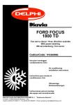
Fig.1A
(I)
Vista componenti montaggio compressore.
1
(F)
Vue des composants nécessaires au montage du
compresseur.
(GB)
View of the components for the compressor assembly.
3
(D)
Ansicht der Einbauteile des Kompressors.
(E)
Vista de los componentes para el montaje del
compresor.
2
4
ELENCO MATERIALE FORNITO / LISTE DU MATERIEL FOURNI / LIST OF SUPPLIED MATERIALS
VERZEICHNIS DES GELIEFERTEN MATERIALS / LISTA MATERIAL ABASTECIDO / LISTA DO MATERIAL FORNECIDO
Pos.
Descrizione / Description / Description / Beschreibung / Descripción
1
Piastra / Plaque / Plate / Träger/ Placa
2
Compressore / Compresseur / Compressor / Kompressor / Compresor
3
Cinghia / Courroie / Belt / Riemen / Correa 6Kx1173
4
Bulloneria / Boulonnerie / Nuts and bolts / Schraubensatz / Tornillería
Codice / Code
Kode / Codigo
001985/5
084014312
013621
7
037VW94/4
MATERIALE FORNITO / MATERIEL FOURNI / SUPPLIED MATERIAL / GELIEFERTES MATERIAL / MATERIAL ABASTECIDO
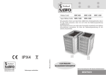
Fig.1.1A
38.3
(I)
Vista dei componenti modifica tubo olio idroguida.
(F)
Vue des composants pour la modification du
tuyau pour huile direction assistée.
39
37.2
(GB)
View of the components for power steering
oil pipe modification.
37.1
(D)
Ansicht der Einbauteile zur Abänderung des
Servolenkungsölschlauches.
38.1
33
38.2
37
(E)
Vista de los componentes para la modificación del tubo aceite hidro-conducción.
38
ELENCO MATERIALE FORNITO / LISTE DU MATERIEL FOURNI / LIST OF SUPPLIED MATERIALS
VERZEICHNIS DES GELIEFERTEN MATERIALS / LISTA MATERIAL ABASTECIDO / LISTA DO MATERIAL FORNECIDO
Pos.
Descrizione / Description / Description / Beschreibung / Descripción
Codice / Code
Kode / Codigo
33
Sacchetto accessori / Sachet accessoires / Bag of accessories / Säckchen mit Zuberhörteilen / Bolsita
accesorios
0231420/1
37
Tubo olio idroguida / Tuyau pour huile direction assistée / Power steering oil pipe / Servolenkungsölschlauch / Tubo aceite hidro-conducción
820AB447/1
37.1
Staffa di supporto tubo olio / Etrier support tuyau d’huile / Oil pipe bracket / Ölschlauch-Halterbügel
Soporte del tubo de aceite
081883
37.2
Fascetta / Collier / Clamp / Schelle / Banda
069077
Tubo olio idroguida / Tuyau pour huile direction assistée / Power steering oil pipe / Servolenkungsölschlauch / Tubo aceite hidro-conducción
068661
38.1
Raccordo / Raccord / Coupling / Verbindungsstück / Racord
069191
38.2
Fascetta / Collier / Clamp / Schelle / Banda
036879
38.3
Protezione termica / Protection thermique / Thermal screen / Wärmeschutz / Protección térmica
070620
Fermatubo / Fixation tuyau/ Pipe clamp / Schlauchbinder / Detiene tubo φ 24
069637
38
39
8
OPERAZIONI PRELIMINARI / OPERATIONS PRELIMINAIRES / PRELIMINARY OPERATIONS
VORBEREITUNGSARBEITEN / OPERACIONES PRELIMINARES / OPERACOES PRELIMINARES
(I)
- Scollegare la batteria.
- Smontare la mascherina frontale completa di indicatori di direzione.
- Smontare il paraurti anteriore.
- Smontare le due barre trasversali di rinforzo e di supporto paraurti anteriore.
- Smontare la calandra frontale completa di gruppi fanali-radiatore-elettroventola.
- Smontare la grembialina inferiore di protezione motore.
- Smontare ed eliminare l’elettroventola (part. “A“ di fig.2A).
- Smontare ed eliminare la cinghia di trasmissione (part. “B“ di fig.2A).
- Smontare l'alternatore (conservare viti di fissaggio).
- Smontare la puleggia pompa idroguida (conservare viti di fissaggio).
- Smontare ed eliminare il tubo olio di collegamento pompa idroguida-scatola sterzo (part. “C” di fig.2A).
- Smontare la pompa idroguida (conservare viti di fissaggio).
- Smontare ed eliminare il supporto alternatore-pompa idroguida (part. “D” di fig.2A) dopo aver smontato il dispositivo tendicinghia
(da riutilizzare).
(F)
- Déconnecter la batterie.
- Déposer l’ensemble plaque frontale et indicateurs de direction.
- Déposer le pare-chocs avant.
- Déposer les deux barres transversales de renforcement et de support pare-chocs avant.
- Déposer l’ensemble calandre-blocs optiques-radiateur-ventilateur.
- Déposer l’écran inférieur du moteur.
- Eliminer le ventilateur (rep. “A” fig. 2A).
- Eliminer la courroie de transmission (rep.”B” fig. 2A).
- Déposer l’alternateur (garder les vis de fixation).
- Déposer la poulie pompe de direction assistée (garder les vis de fixation).
- Eliminer le tuyau d’huile de raccordement pompe de direction assistée-boîtier de direction (rep.”C” fig. 2A).
- Déposer la pompe de direction assistée (garder les vis de fixation).
- Eliminer le support alternateur-pompe de direction assistée (rep.”D” fig. 2A) après avoir déposé le tendeur de courroie (à reutiliser).
(GB)
- Disconnect the battery.
- Remove the front plate and the turn indicators.
- Remove the front bumper.
- Remove the front bumper stiffening and support transverse bars.
- Remove the front radiator grill with the headlights-radiator-fan.
- Remove the lower engine screen.
- Discard the fan (part “A” fig. 2A).
- Discard the driving belt (part “B” fig. 2A).
- Remove the alternator (keep the fixing screws).
- Remove the power steering pump (keep the fixing screws).
- Discard the oil pipe which connects the power steering pump to the steering box (part “C” fig. 2A).
- Remove the power steering pump (keep the fixing screws).
- Discard the alternator-power steering pump support (part “D” fig. 2A) after having removed the belt stretcher (to be reused).
9
(D)
- Die Batterie lösen.
- Die Frontalblende komplett mit Blinkern ausbauen.
- Die vordere Stosstange ausbauen.
- Die zwei Querträger zur Verstärkung und zur Halterung der vorderen Stosstange ausbauen.
- Die Motorraumverkleidung komplett mit Scheinwerfer-Kühler-Elektrolüfter-Gruppe ausbauen.
- Die untere Abdeckung zum Motorschutz ausbauen.
- Den Elektrolüfter (Teil "A" der Abb.2A) ausbauen und entfernen.
- Den Antriebsriemen (Teil "B" der Abb.2A) ausbauen und entfernen.
- Den Drehstromgenerator ausbauen (die Befestigungsschrauben aufbewahren).
- Die Riemenscheibe der Servolenkungspumpe ausbauen (die Befestigungsschrauben aufbewahren).
- Den Ölschlauch - Verbindung der Servolenkungspumpe und der Steuerungsbox ausbauen und entfernen (Teil "C" der Abb.2A).
- Die Servolenkungspumpe ausbauen (die Befestigungsschrauben aufbewahren).
- Nach Ausbau der Riemenspannervorrichtung (wieder zu verwenden), den Drehstromgenerators-Servolenkungspumpe-Halter (Teil
"D" der Abb.2A) ausbauen und entfernen.
(E)
- Desmontar la batería.
- Desmontar la placa porta-mandos frontal que contiene los indicadores de dirección.
- Desmontar el parachoques delantero.
- Desmontar las dos barras transversales de refuerzo y de soporte del parachoques delantero.
- Desmontar la calandra frontal que contiene los grupos de faros-radiador-electroventilador.
- Desmontar la protección inferior del motor.
- Desmontar y eliminar el electroventilador "A" de la fig. 2A).
- Desmontar y eliminar la correa de transmisión (parte "B" de la fig. 2A).
- Desmontar el alternador (conservar los tornillos de fijación).
- Desmontar la polea de la bomba de la servo dirección (conservar los tornillos de fijación).
- Desmontar y eliminar el tubo del aceite de conexión de la bomba servo dirección caja de dirección (parte "C" de la fig. 2A).
- Desmontar la bomba de la servo dirección (conservar los tornillos de fijación).
- Desmontar y eliminar el soporte del alternador bomba servo dirección (parte "D" de la fig. 2A) después de haber desmontado el
dispositivo de tensionamiento de correa (que hay que utilizar).
10
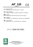
Fig.2A
(I)
Vista dei componenti originali da eliminare:
A) Elettroventola; B) Cinghia di trasmissione; C) Tubo olio
idroguida di mandata; D) Supporto alternatore-pompa idroguida.
(F)
Vue des composants d’origine à éliminer:
A) Ventilateur; B) Courroie de transmission; C) Tuyau d’huile
de refoulement direction assistée; D) Support alternateurpompe de direction assistée.
(GB)
View of the original parts to be discarded:
A) Fan; B) Driving belt; C) Delivery power steering oil pipe; D)
Alternator-power steering pump support.
(D)
Ansicht der zu entfernenden Originalbestandteile:
A) Elektrolüfter; B) Antriebsriemen; C) ServolenkungsZufuhrölschlauch; D) Drehstromgenerator-Servolenkungspumpen-Halter.
(E)
Vista de los componentes originales que hay que eliminar:
A) Electroventilador; B) Correa de transmisión; C) Tubo del
aceite de la servo dirección de envío; D) Soporte alternador–
bomba servo dirección.
A
D
C
B
Fig.3A
(I)
Vista dei punti "a-b" (fori filettati sul blocco motore) da utilizzare per il fissaggio della piastra fornita (1).
a
(F)
Vue des points "a-b" (trous filetés sur le bloc moteur), à utiliser pour le fixage de la plaque fournie (1).
(GB)
View of points "a-b" (threaded holes on the erigine block)
they are to be used to secure the supplied plate (1).
(D)
Ansicht der für die Befestigung des Trägers (1) zu verwendenen Punkte "a-b" (Gewindebohrungen am Motorblock).
(E)
Vista de los puntos "a-b" (orificios fileteados en el bloque
motor) a utilizar para el ajuste de la placà abastecida (1).
b
11
Fig.4A
(I)
Rappresentazione schematico-riassuntiva dello
staffaggio compressore
con indicazione della relativa bulloneria di fissaggio.
(F)
Rèprèsentation schèmatique-rècapitulative des
étriers
compresseur
avec indications de la
boulonnerie de fixage
correspondante.
(GB)
Recapitulatory diagram
of the compressor bracketing and indications of
the fixing nuts and bolts.
(D)
Schematische
Gesamtdarstellung
der
Verbügelung des Kompressors, mit Hinweisen
der entsprechenden Befestigungsschrauben
und -muttern.
(E)
Representación esquematica recopilativa del
anclaje compresor, con
indicaciones de la relativa tornilleria de ajuste.
BULLONERIA DA UTILIZZARE / BOULONNERIE A UTILISER / NUTS AND BOLTS TO BE USED / ZU BENUTZENDER SCHRAUBENSATZ/ TORNILLERIA A UTILIZAR / PARAFUSOS ARRUELAS E PORCAS A SAREM UTILIZADOS
Pos.
Descrizione / Description / Description / Beschreibung / Descripción
12
Vite TCE / Vis à tête cylindrique / Allen head screw/Sechskant-Zylinderschraube / Tornillo cabeza cilindrica con hexágono
M8x95
13
Vite TE / Vis à tête à six pans / Hexagonal head screw/Sechskantschraube / Tornillo cabeza hexagonal M8x40
14
Vite TE / Vis à tête à six pans / Hexagonal head screw / Sechskantschraube / Tornillo cabeza hexagonal M10x30
16
Vite TCE / Vis à tête cylindrique / Allen head screw/Sechskant-Zylinderschraube / Tornillo cabeza cilindrica con hexágono
M10x65
17
Vite TCE / Vis à tête cylindrique / Allen head screw/Sechskant-Zylinderschraube / Tornillo cabeza cilindrica con hexágono
M10x75
18
Vite TCE / Vis à tête cylindrique / Allen head screw/Sechskant-Zylinderschraube / Tornillo cabeza cilindrica con hexágono
M10x40
19
Rondella ondulata / Rondelle ondulée / Corrugated washer / Wellscheibe / Arandela ondulada φ 8
20
Rondella ondulata / Rondelle ondulée / Corrugated washer / Wellscheibe / Arandela ondulada φ 10
21
Vite TCE / Vis à tête cylindrique / Allen head screw/Sechskant-Zylinderschraube / Tornillo cabeza cilindrica con hexágono
M10x100
12
1
1
D
12
D
ORIGINALE
ORIGINAL
19
ORIGINALE
ORIGINAL
13
ORIGINALI
ORIGINALS
19
I
I
Fig.5A
(I)
Fissare, a banco, il dispositivo tendicinghia originale "D" (recuperato) e la pompa idroguida "l" alla piastra "1" utilizzando bulloneria
fornita e bulloneria originale, secondo le indicazioni di figura.
(F)
A l'établi, fixer le tendeur de courroie original "D" et la pompe de direction assistée "I" a la plaque "1" en utilisant la boulonnerie
fournie et la boulonnerie originale selon les indications de la figure.
(GB)
At,the bench, secure the original idler "D" and the power steering pump "l" to the plate "1" by means of the original and supplied
nuts and bolts according to the indications of the picture.
(D)
An der Werkbank die Original-Riemenspannvorrichtung "D" (aufbewahrt) und die Hydrotenkungspumpe "I" an den Träger "1" befestigen, dabei den gelieferten und den Original-Schraubensatz, laut den Hinweisen der Abbildung, benützen.
(E)
Fijar, sobre banco, el dispositivo tensor de correa de origen "D" (recuperado) y la bomba hidro-conducción "l" a la placa "1" utilizando
la tornilleria suministrada y la tornilleria de origen siguiendo las indicaciones de la figura.
BULLONERIA DA UTILIZZARE / BOULONNERIE A UTILISER / NUTS AND BOLTS TO BE USED / ZU BENUTZENDER SCHRAUBENSATZ/ TORNILLERIA A UTILIZAR / PARAFUSOS ARRUELAS E PORCAS A SAREM UTILIZADOS
Pos.
Descrizione / Description / Description / Beschreibung / Descripción
12
Vite TCE / Vis à tête cylindrique / Allen head screw / Sechskant-Zylinderschraube / Tornillo cabeza cilindrica con hexágono
M8x95
13
Vite TE / Vis à tête à six pans / Hexagonal head screw / Sechskantschraube / Tornillo cabeza hexagonal M8x40
19
Rondella ondulata / Rondelle ondulée / Corrugated washer / Wellscheibe / Arandela ondulada φ 8
13
Fig.6A
20 18
16 20
1
(I)
Fissare l’assieme piastra ”1”-pompa idroguida ”I” al blocco
motore in corrispondenza dei punti “a-b” descritti in fig. 3A.
Durante il montaggio della piastra, forzare leggermente la
protezione dei collettori di scarico, nella zona indicata da freccia in figura.
Procedere al montaggio del compressore (2) e dell’alternatore
seguendo le indicazioni della rappresentazione schematica di
fig. 4A.
(F)
Fixer l’ensemble plaque "1"-pompe de direction assistée "I"
au bloc moteur aux points "a-b" décrits sur la fig. 3A.
Pendant la pose de la plaque, forcer un peu la protection des
collecteurs de décharge à l’emplacement indiqué par la flèche
sur la figure.
Poser le compresseur (2) et l’alternateur en suivant les indications de la synthèse schématique de fig. 4A.
(GB)
Secure the plate "1" and the power steering pump "I" assy
to the cylinder block in the points "a-b" of fig. 3A.
During the plate assembly, slightly force the dicharge manifolds screen in the area indicated by the arrow in the picture.
Assemble the compressor (2) and the alternator according to
the indications of the diagram of fig. 4A.
20 21
I
17 20
(D)
Die Platten "1"-Servolenkungspumpen "I" Gruppe am Motorblock an den Punkten "a-b", in der Abb.3A beschrieben, befestigen. Während des Einbaues der Platte, den Schutz des
Abflusskrümmers in dem der Abbildung mit Pfeilen gekennzeichneten Bereich leicht biegen.
Mit dem Einbau des Kompressors (2) und des Drehstomgenerators fortschreiten, indem die Angaben der schematischen
Darstellung der Abb.4A beachtet werden.
(E)
Fijar el grupo placa "1" bomba servo dirección "I" en el grupo motor en correspondencia con los puntos "a-b" descritos en la fig.
3A. Durante el montaje de la placa, forzar muy suave la protección de los colectores de descarga, en la zona indicada por la flecha
en la figura.
Proceder al montaje del compresor (2) y del alternador siguiendo las indicaciones de la representación esquemática de la fig. 4A.
BULLONERIA DA UTILIZZARE / BOULONNERIE A UTILISER / NUTS AND BOLTS TO BE USED / ZU BENUTZENDER SCHRAUBENSATZ/ TORNILLERIA A UTILIZAR / PARAFUSOS ARRUELAS E PORCAS A SAREM UTILIZADOS
Pos.
Descrizione / Description / Description / Beschreibung / Descripción
16
Vite TCE / Vis à tête cylindrique / Allen head screw/Sechskant-Zylinderschraube / Tornillo cabeza cilindrica con hexágono
M10x65
17
Vite TCE / Vis à tête cylindrique / Allen head screw/Sechskant-Zylinderschraube / Tornillo cabeza cilindrica con hexágono
M10x75
18
Vite TCE / Vis à tête cylindrique / Allen head screw/Sechskant-Zylinderschraube / Tornillo cabeza cilindrica con hexágono
M10x40
20
Rondella ondulata / Rondelle ondulée / Corrugated washer / Wellscheibe / Arandela ondulada φ 10
21
Vite TCE / Vis à tête cylindrique / Allen head screw/Sechskant-Zylinderschraube / Tornillo cabeza cilindrica con hexágono
M10x100
14
Fig.7A
M
D
3
2
A
(I)
Rimontare come in origine la puleggia
della pompa idroguida. Montare la cinghia di trasmissione fornita “3” collegandola come visibile in figura,
allineandola sull’elettropuleggia del
compressore “2” secondo l’indicazione
del riquadro.
A) Puleggia alternatore; D) Puleggia tenditore automatico; I) Puleggia idroguida;
M) Puleggia motore.
(F)
Reposer la poulie de la pompe direction
assistée dans sa position. Poser la courroie de transmission fournie "3" et la
raccorder comme indiqué ci-contre en
l’alignant sur l’embrayage du compresseur "2" selon les indications de la figure.
A) Poulie alternateur; D) Poulie tendeur
automatique; I) Poulie direction assistée; M) Poulie moteur.
I
(GB)
Reassemble the power steering pump
pulley in the original position. Assemble
the supplied driving belt "3" and connect it as shown in the picture; align it
on the compressor clutch "2" according
to the indication of the inset.
A) Alternator pulley; D) Automatic belt
stretcher pulley; I) Power steering pulley; M) Driving pulley
(D)
Die Servolenkungspumpen-Riemenscheibe wieder in die Originalposition einbauen. Den gelieferten Antriebsriemen "3" einbauen und
wie in der Abb. ersichtlich, an der elektromagnetischen Kupplung des Kompressors "2" ausrichten.
A) Lichtmaschinen-Riemenscheibe; D) Riemenscheibe der automatischen Spannrolle; I) Servolenkungs-Riemenscheibe; M) Motorriemenscheibe
(E)
Volver a montar como en su origen la polea de la bomba hidro-conducción. Montar la correa de transmisión suministrada "3", conectándola como visible en la figura, poniendola en alineación sobre a la electropolea del compresor "2", según la indicación del
recuadro.
A) Polea alternador; D) Polea tensor automático; I) Polea hidro-conducción; M) Polea motor.
15
37
I
Fig.8A
(I)
Montare il tubo olio idroguida fornito “37“ in sostituzione del tubo originale
eliminato collegandolo alla scatola dello sterzo (riutilizzare raccordo e rondelle
di tenuta pre-esistenti) ed alla pompa idroguida “I” mediante raccordo predisposto sul tubo stesso. Bloccare il tubo ad incastro in corrispondenza dei fermi originali predisposti ed al compressore, utilizzando staffa “37.1“ e fascetta
”37.2“ come da riquadro di figura.
37.4 37.3
37.2
37.1
37
BULLONERIA DA UTILIZZARE / BOULONNERIE A UTILISER / NUTS AND BOLTS TO BE USED / ZU BENUTZENDER SCHRAUBENSATZ/ TORNILLERIA A UTILIZAR / PARAFUSOS ARRUELAS E PORCAS A SAREM UTILIZADOS
Pos.
Descrizione / Description / Description / Beschreibung / Descripción
37.3
Vite TE / Vis à tête à six pans / Hexagonal head screw / Sechskantschraube / Tornillo cabeza hexagonal M6x16
37.4
Dado autobloccante / Ecrou autobloquant / Self-locking nut / Selbstsperrende Mutter / Tuerca autobloqueante M6
16
Fig.8A
(F)
Poser le tuyau d’huile de direction assisté fourn "37" à la place du tuyau d’origine éliminé et le raccorder au boîtier de direction
(reutiliser le raccord et les rondelles d’origine) et à la pompe de direction assistée "I" à l’aide du raccord disponible sur le tuyau. Fixer
le tuyau aux arrêtoirs d’origine disponibles et au compresseur en utilisant l’étrier "37.1" et le collier "37.2" comme indiqué sur la
figure.
(GB)
Assemble the supplied power steering oil pipe "37" in the place of the original discarded one and connect it to the steering box
(reuse the original coupling and washers) and to the power steering pump "I" by means of the coupling prepared on the pipe. Secure
the pipe to the original retainers and to the compressor by means of the bracket "37.1" and clamp "37.2" as shown in the picture.
(D)
Den gelieferten Servolenkungs-Ölschlauch "37" anstelle des entfernten Originalschlauches einbauen, indem er an die Steuerungsbox
(das Verbindungsstück und die vorhandenen Stützscheiben wiederverwenden) und mittels schon vorhandenen Verbindungsstück am
Schlauch, an die Servolenkungs-Pumpe angeschlossen wird. Den Schlauch bis zum Einrasten an den vorhandenen Originalbefestigungen und mittels Bügel "37.1" und Schellle "37.2" wie im Detail der Abbildung ersichtlich - blockieren.
(E)
Montar el tubo del aceite de la servo dirección "37" en sustitución del tubo original eliminado conectándolo a la caja de la dirección
(volviendo a utilizar el racord y la arandela de estanqueidad pre-existentes) y a la bomba servo dirección "I", mediante racord preparado en la tubo mismo. Bloquear el tubo encastrándolo en correspondencia con los bloqueos originales preparados y en el compresor,
utilizando el soporte "37.1" y abrazadera "37.2" como se ve en el recuadro de la figura.
17
A
To
38.1
39
To
38.2
38.2
38
38.3
38
37
38.2
38
39
39
I
ELIMINARE
ELIMINER
DISCARD
ENTFERNEN
ELIMINAR
B
37
39
140 mm
I
ORIGINALE
ORIGINAL
Fig.9A
Inserire il raccordo “38.1“ sul tubo “38“ e bloccarlo mediante fascetta “38.2“. Rivestire il tubo ”38“ con protezione termica “38.3“
come visibile nel riquadro (A). Tagliare ed eliminare la parte del tubo olio originale “To”, sul lato di innesto alla pompa idroguida “I”,
seguendo l’indicazione del riquadro (B).
Collegare il tubo olio “38“: alla parte conservata del tubo originale “To”, bloccandolo con fascetta “38.2“ e alla pompa idroguida “I”
mediante fascetta originale recuperata.
Bloccare tra loro i tubi olio “37” e “38” mediante fermatubi “39”.
18
Fig.9A
(F)
Introduire le raccord "38.1" sur le tuyau "38" et le fixer à l’aide du collier "38.2". Appliquer la protection thermique "38.3" sur le
tuyau "38" comme visible sur la figure (A). Couper et éliminer la partie du tuyau d’huile d’origine "To" sur le côté de raccordement
à la pompe de direction assistée "I" en suivant l’indication de la figure (B).
Raccorder le tuyau d’huile "38" à la partie gardée du tuyau d’origine "To" et le fixer à l’aide du collier "38.2" et à la pompe de
direction assistée "I" à l’aide d’un collier d’origine récupéré.
Fixer les tuyaux d’huile "37-38" entre eux à l’aide des colliers "39".
(GB)
Insert the coupling "38.1" in the pipe "38" and secure it by means of clamp "38.2". Apply the thermal screen "38.3" on the pipe
"38" as shown in the picture (A). Cut and discard the part of the original oil pipe "To" on the connection side to the power steering
pump "I" according to the indications of fig. (B).
Connect the oil pipe "38" to the original pipe kept part "To" and secure it by means of clamp "38.2" and to the power steering pump
"I" by means of original clamp.
Secure the oil pipes "37-38" to each other by means of clamps "39".
(D)
Das Verbindungsstück "38.1" in den Schlauch "38" einsetzen und mittels Schelle "38.2" blockieren. Den Schlauch "38" mit den
Wärmeschutz "38.3", wie im Detail (A) ersichtlich, ummanteln. Den Teil des Originalölschlauches "To", seitlich des Anschlusses
an die Servolenkungspumpe "I", abschneiden und entfernen, die Angaben des Details (B) beachten.
Den Ölschlauch wie folgt anschliessen: mittels Schelle "38" an den aufbewahrten Teil des Originalschlauches "To" und mittels aufbewahrter Originalschelle an die Servolenkungspumpe "I".
Die Ölschläuche "37" und "38" mittels Schlauchbindern "39" untereinander blockieren.
(E)
Introducir el racord "38.1" en el tubo "38" y bloquearlo con abrazadera "38.2". Cubrir el tubo "38" con protección térmica "38.3"
como se ve en el recuadro (A). Cortar y eliminar la parte del tubo del aceite original "To" en el lado de la unión de la bomba de la
servo dirección "I", siguiendo las indicaciones del recuadro (B).
Conectar el tubo "38" a la parte conservada del tubo original "To", bloqueándolo con abrazadera "38.2" y a la bomba de la servo
dirección "I" usando abrazadera original recuperada.
Bloquear entre ellos los tubos del aceite "37" y "38"usando detiene tubos "39".
19
MONTAGGIO FILTRO ESSICCATORE/ POSE DU FILTRE DESHYDRATEUR / RECEIVER DRIER ASSEMBLY
TROCKNERFILTER EINBAU / MONTAJE DEL FILTRO SECADOR / MONTAGEM DO FILTRO SECADOR
MATERIALE FORNITO / MATERIEL FOURNI / SUPPLIED MATERIAL / GELIEFERTES MATERIAL / MATERIAL ABASTECIDO / MATERIAL FORNECIDO
Fig.1B
(I)
Vista componenti montaggio filtro essiccatore.
(F)
Vue des composants nécessaires au montage du filtre déshydrateur.
53
52
(GB)
View of the components for the receiver drier assembly.
(D)
Ansicht der Einbauteile des Trocknerfilters.
(E)
Vista de los componentes para el montaje del filtro secador.
51
ELENCO MATERIALE FORNITO / LISTE DU MATERIEL FOURNI / LIST OF SUPPLIED MATERIALS
VERZEICHNIS DES GELIEFERTEN MATERIALS / LISTA MATERIAL ABASTECIDO / LISTA DO MATERIAL FORNECIDO
Pos.
Descrizione / Description / Description / Beschreibung / Descripción
Codice / Code
Kode / Codigo
51
Staffa filtro / Etrier filtre / Receiver drier bracket / Filterbügel / Abrazadera filtro
0361170
52
Filtro essiccatore / Filtre déshydrateur / Receiver drier / Trocknerfilter / Filtro secador
017047/1
53
Pressostato / Pressostat / Pressure switch / Druckwächter / Presostato
043118/1
20
Fig.2B
51
53
(I)
Fissare la staffa supporto filtro “51” alle viti esistenti nei punti “a”.
Inserire nella staffa il filtro essiccatore “52” completo di pressostato
“53” e bloccarlo nella posizione di figura.
(F)
Fixer l'étrier de support fìitre “51” au niveau des vis existantes aux
points “a” . lnsérer dans l'étrier le filtre séchoir “52” compiet de pressostat “53” et le bioquer à la position de la figure.
ORIGINALI
ORIGINALS
a
(GB)
Secure the receiver drier suppo,rt bracket “51” to the screws found
at poihts “a”. lnsert the receiver drier “52”, together wíth pressure
switch “53” on to the bracket and lock in the position indicated in
the figure.
(D)
Filter-Haltebügel “51” an in den Punkten “a” vorhandenen Schrauben befestigen.
In den Halter den Trócknerfilter “52” mít
Druckwächter “53” einsetzen und ín Position der Abbìidung festziehen.
52
(E)
Fijar la abrazadera de soporte filtro “51” a los tornilios existentes en
los puntos “a”. Inserir en la abrazadera el filtro secador “52” inciuyendo presostato “53” y bìoquearlo en la posición de la figura.
21
MONTAGGIO CONDENSATORE / POSE DU CONDENSEUR / CONDENSER FITTING
KONDENSATOREINBAU / MONTAJE CONDENSADOR
MATERIALE FORNITO / MATERIEL FOURNI / SUPPLIED MATERIAL / GELIEFERTES MATERIAL / MATERIAL ABASTECIDO
Fig.1C
40
34
35
(F)
Vue des composants pour le montage du
condenseur et du ventilateur.
41
32
(I)
Vista componenti montaggio condensatore
ed elettroventola.
(GB)
View of the condenser and fan assembly
components.
(D)
Ansicht der Kondensator-Elektrolüfter-Einbauteile.
33
(E)
Vista componentes montaje condensador
electroventilador.
36
31
ELENCO MATERIALE FORNITO / LISTE DU MATERIEL FOURNI / LIST OF SUPPLIED MATERIALS
VERZEICHNIS DES GELIEFERTEN MATERIALS / LISTA MATERIAL ABASTECIDO
Pos.
Descrizione / Description / Description / Beschreibung / Descripción
Codice / Code
Kode / Codigo
31
Condensatore / Condenseur / Condenser / Kondensator / Condensador
024081
32
Elettroventola / Electroventilateur / Electric fan / Elektrogebläse / Electroventilador
026168
33
Sacchetto accessori / Sachet accessories / Bag of accessories / Säckchen mit Zubehörteilen / Bolsita
accesorios
0231420/1
34
Resistore / Résistance / Resistor / Widerstand / Resistor
0681112/2
35
Staffa resistore / Etrier résistance / Resistor bracket / Widerstandsbügel / Estribo resistor
36
Gommino passatubo / Pièce en caoutchouc passe-fil / Rubber pipe lead / Gummitülle / Goma pasatubo
069031
40
Gommino fissaggio elettroventola / Caoutchouc de fixation ventilateur / Fan fixing rubber grommet /
Gummitülle zur Elektrolüfterbefestigung / Goma fisacion ventilador
082003/1
41
Distanziale per gommino / Entretoise pour piéce en caoutchouc / Rubber grommet spacer / Abstandsstück für Gummitüllen / Distanciador para pasamuros
082003.2
22
0811266
Fig.2C
(I)
Fissare il condensatore "31" al radiatore in corrispondenza
dei fori esistenti ai punti "a-b". Forare (φ 34mm) in corrispondenza del punto “c” ed inserire il gommino "36".
(F)
Fixer le condenseur "31" au radiateur au niveau des trous
"a-b". Percer (φ 34 mm) en "c" et introduire le caoutchouc
"36".
31
c
b
a
36
31.1
31.1
31.2
31.2
(GB)
Secure the condenser "31" to the radiator over the holes "a-b". Drill φ 34 mm in the point "c" and insert the rubber grommet "36".
(D)
Den Kondensator "31", in Übereinstimmung mit den an den Punkten "a-b" befindlichen Bohrungen, am Kühler befestigen. Am Punkt
"c" eine Bohrung von φ 34 mm durchführen und die Gummitülle "36" einführen.
(E)
Fijar el condensador "31" al radiador en correspondencia de los orificios existentes en los puntos "a-b". Perforar φ 34 mm en correspondencia del punto "c" e insertar la goma "36".
ELEMENTI DI FISSAGGIO / PIECES DE FIXATION / FIXING PARTS / BEFESTIGUNGSELEMENTE
ELEMENTOS DE FIJACION / ELEMENTOS DE FIXACAO
Pos.
Descrizione / Description / Description / Beschreibung / Descripción
Codice / Code
Kode / Codigo
31.1
Vite autofilettante TE / Vis autotaradeuse à tête à six pans / Self-tapping hexagonal head screw / Selbstschneidende Sechskantschraube / Tornillo autoenroscante cabeza hexagonal 6,3x16
-
31.2
Rondella piana / Rondelle plate / Plain washer / Flache U-Scheibe / Arandela llana φ 6
-
23
Fig.3C
(I)
Bloccare l’elettroventola "32" al convogliatore aria in corrispondenza dei fori predisposti "e-f-g" utilizzando: gommini antivibranti “40”, relativi distanziali interni
”41”, viti e rondelle; come illustrato nella rappresentazione schematica di figura.
32.1
32.2
(F)
Fixer le ventilateur “32“ au convoyeur d'air au niveau des trous disponibles “e-fg“ à l'aide des silentblocks “40“, des entretoises internes “41“, de vis et de rondelles, comme illustré sur le schéma de la figure.
40
32
41
32.2 32.1
e
e-f-g
(GB)
Secure the fan “32“ to the air conveyor
over the prepared holes “e-f-g“ by means
of Silent-Blocks “40“ , their inner spacers
“41“ , screws and washers as illustrated
in the diagram of the picture.
(D)
Den Elektrolüfter “32“ mittels Gummifederelementen “40“, dazugehörigen inneren
Abstandsstücken “41“, Schrauben und UScheiben an der Luftführung an den vorbereiteten Bohrungen “e-f-g“ blockieren; wie
in der schematischen Darstellung der Abb.
ersichtlich.
g
32.1
32.2
32
f
32.1 32.2
(E)
Bloquear el electroventilador “32“ en el canalizador del aire en correspondencia con los orificios preparados “e-f-g“ utilizando:
cauchos antivibrantes “40“, relativos distanciadores interiores “41“, tornillos y arandelas; como se ve en la representación
esquemática de la figura.
ELEMENTI DI FISSAGGIO / PIECES DE FIXATION / FIXING PARTS
BEFESTIGUNGSELEMENTE / ELEMENTOS DE FIJACION
Pos.
Descrizione / Description / Description / Beschreibung / Descripción
Codice / Code
Kode / Codigo
32.1
Vite TE / Vis à tête à six pans / Hexagonal head screw / Sechskantschraube / Tornillo cabeza hexagonal
M6x25
-
32.2
Rondella piana / Rondelle plate / Plain washer / Flache U-Scheibe / Arandela llana φ 6xφ 18x2
-
24
Fig.4C
35.3
34
35.2
35.1
35.1
35
35.2
35.3
32.5 32.4 32.3
h
35
(I)
Fissare il resistore “34” alla staffa
“35” mediante bulloneria M5. Fissare la staffa "35" in corrispondenza
del punto "h". Rimontare la calandra
frontale, completa di condensatore
ed elettroventola.
(F)
Fixer la résistance "34" à l’étrier
"35" à l’aide de la boulonnerie M5.
Fixer l’étrier "35" en "h" à l’aide des
rondelles fournies et des vis existantes. Reposer la calandre frontale,
avec le condenseur et l’électroventilateur. Rèmonter la calandre frontale
complète de condenseur et elèctroventilateur.
(GB)
Secure the resistor "34" to the bracket "35" by means of the M5 nuts
and bolts. Secure the bracket "35"
in the point "h" by means of the supplied washer and existing screws.
Replace the original radiator thermoswitch "Bo" with the one provided
"36". Remount the front radiator
grill, together with condenser and
electric fan.
(D)
Den Widerstand "34" mittels
Schraubensatz M5 am Bügel "35"
befestigen. Den Bügel mittels gelieferter U-Scheibe und vorhandenen
Schrauben, in Übereinstimmung mit
dem Punkt "h", befestigen. Kühlergrill
mit
Kondensator
und
Elektrogebläse_wieder
einbauen.
Kühlerverkleidung mit Kondensator
und Elektrogebläse wieder eimbauen.
32
(E)
Fijar el resistor "34" al estribo "35" por medio de tornilleria M5. Fijar el estribo "35" en correspondencia del punto "h" utilizando la
arandela suministrada y los tornillos existentes. Volver a montar la calandria frontal, incluyendo condensador y electroventilador.
Volver a montar la calandria frontal, incluyendo condensador y eléctroventilador.
ELEMENTI DI FISSAGGIO / PIECES DE FIXATION / FIXING PARTS / BEFESTIGUNGSELEMENTE
ELEMENTOS DE FIJACION / ELEMENTOS DE FIXACAO
Pos.
Descrizione / Description / Description / Beschreibung / Descripción
32.3
Vite TE / Vis à tête à six pans / Hexagonal head screw / Sechskantschraube / Tornillo cabeza hexagonal M6x16
32.4
Rondella piana / Rondelle plate / Plain washer / Flache U-Scheibe / Arandela llana φ 6
32.5
Dado autobloccante / Ecrou autobloquant / Self-locking nut / Selbstsperrende Mutter / Tuercaautobloqueante M6
35.1
Vite TE / Vis à tête à six pans / Hexagonal head screw / Sechskantschraube / Tornillo cabeza hexagonal M5x16
35.2
Rondella piana / Rondelle plate / Plain washer / Flache U-Scheibe / Arandela llana φ 5
35.3
Dado autobloccante / Ecrou autobloquant/Self-locking nut / Selbstsperrende Mutter / Tuerca autobloqueante M5
25
MONTAGGIO COMPONENTI A.C. NELL’ABITACOLO (parte evaporante-comandi)
POSE DES COMPOSANTS A.C. DANS L’HABITACLE (évaporateur-commandes)
A.C. COMPONENTS ASSEMBLY IN THE PASSENGER COMPARTMENT (evaporator-controls)
EINBAU DER KLIMAANLAGEN-BESTANDTEILE IM WAGENINNEREN (Seite der Verdampfersteuerung)
MONTAJE COMPONENTES A.C. EN EL HABITACULO (parte evaporador-mandos)
MONTAGEM DOS COMPONENTES A.C. NO INTERIOR DO VEICULO (evaporador-controles)
MATERIALE FORNITO / MATERIEL FOURNI / SUPPLIED MATERIAL / GELIEFERTES MATERIAL / MATERIAL ABASTECIDO / MATERIAL FORNECIDO
Fig.1D
64
63
65
(I)
Vista componenti montaggio evaporatore.
61
(F)
Vue des composant nécessaire au montage
de l’évaporateur.
(GB)
View of the evaporator assembly components.
73
(D)
Ansicht der Einbauteile des Verdampfers.
71
(E)
Vista de los componentes para el montaje
del evaporador.
67.1
62
67
72
0281866/1
102
103
MAN039/1
98
104
97
91
99
96
100
Fig.1.1D
(I)
Vista componenti Impianto Elettrico Comandi.
(F)
Vue des composants du faisceau électrique
des commandes.
(GB)
View of the controls electric system components.
(D)
Ansicht der Einbauteile der elektrischen Bedienungsanlage.
101
26
(E)
Vista de los componentes de la instalación
eléctrica comandos.
ELENCO MATERIALE FORNITO / LISTE DU MATERIEL FOURNI / LIST OF SUPPLIED MATERIALS
VERZEICHNIS DES GELIEFERTEN MATERIALS / LISTA MATERIAL ABASTECIDO
Pos.
Descrizione / Dèscription / Description / Beschreibung / Descripción
Codice / Code
Kode / Codigo
61
Gruppo evaporatore / Groupe évaporateur / Evaporating unit / Verdampfereinheit / Grupo evaporador
030812/2
62
Staffa supporto evaporatore / Etrier support évaporateur / Evaporator support bracket / Verdampfer-Haltebügel / Abrazadera soporte evaporador
0601252/1
63
Raccordo scarico condensa / Raccord écoulement condensat / Condensate drain union / Kondenswasserabflußanschlauch / Empalme descarga condensación
007586
64
Gommino φ16 / Pièce en caoutchouc φ16 / Rubber lead φ16 / Gummizwischenlage φ16 / Goma φ16
069013
65
Tubo scarico condensa / Tuyau d’écoulement des condensations / Condensate drain pipe / Kondenserwasserablußschlauch / Tubo descarga condensación
069007
67
Mastice anticondensa / Mastic anti-condensation / Condensation-proofing material / Kondenserwasserdichtemasse / Masilla anticondensación
070001
67.1
Confezione antiruggine / Produit antiroullie / Rust-preventer / Rostchutzverpackung / Confección anti-orin
041098
71
Sacchetto accessori / Sachet accessoires / Bag of accessories / Säckchen mit Zuberhörteilen / Bolsita
accesorios
029586/2
72
Grembialina copri-evaporatore / Volet de protection évaporateur / Evaporator cover screen / Verdampferabdeckung / Pantalla cubre-evaporador
0321568/3
73
Flangia passatubo / Bride pour pièce en caoutchouc passe-tuyaux / Rubber pipe flange / Flansch fuer Gummitülle / Brida para goma pasatubo
0321429/1
91
Impianto Elettrico Comandi / Faisceau Électrique Commandes / Electrical system for controls / Elektrische
Anlage der Bedienungseinheit/ Instalación Eléctrica Comandos
0281866/1
96
Connettore a 1 via / Connecteur à 1 voie / 1-way connector / 1-Weg-Steckverbinder / Conectador 1 vía
-
97
Connettore a 1 via / Connecteur à 1 voie / 1-way connector / 1-Weg-Steckverbinder / Conectador 1 vía
-
98
Relé doppio interruttore + doppio diodo/Relais double interrupteur+double diode / Double switch relay+double diode / Relais-Doppelschalter+Doppeldiode / Relé doble interruptor+doble diodo
0681240
99
Gommino passacavo / Pièce en caoutchouc passe-fil / Rubber grommet for cables / Gummitülle / Goma
pasacable
069013
100
Cavallotto / Cavalier / Shunt / Bügelbolzen / Perno de orquilla
101
Interruttore di comando A.C. / Interrupteur de commande A.C. / A.C. control switch / Klimaanlagenschalter / Interruptor de comando A.C.
0682022
102
Staffa di supporto relé / Support relais / Relay support / Relais-Halterbügel / Estribo de soporte relé
0681510
103
Connettore PACKARD 1 via / Connecteur PACKARD à 1 voie / 1-way PACKARD connector / 1-WegPACKARD-Steckverbinder / Conector PACKARD 1vía
-
104
Connettore PACKARD 3 vie / Connecteur PACKARD à 3 voies / 3-way PACKARD connector / 3-WegPACKARD-Steckverbinder / Conector PACKARD 3 vías
-
27
-
OPERAZIONI PRELIMINARI / OPERATIONS PRELIMINAIRES / PRELIMINARY OPERATIONS
VORBEREITUNGSARBEITEN / OPERACIONES PRELIMINARES / OPERACOES PRELIMINARES
G
A
B
C
H
D
E
F
Fig.2D
(I)
NEL VANO MOTORE ZONA VASCA SERVIZI:
Smontare grembialina destra di copertura microfiltro e presa aria dinamica.
Smontare micro-filtro.
Smontare la cornice sede micro-filtro.
NELL’ABITACOLO:
Smontare la mascherina serigrafica (A) del gruppo comandi: riscaldamento-distribuzione aria e ventilazione.
Sbloccare la cuffia della leva cambio (B) dalla propria sede.
Sbloccare la cornice (C) della leva freno di stazionamento.
Togliere le viti di fissaggio del tunnel leva cambio- leva freno di stazionamento (D).
Spostare leggermente verso la zona posteriore dell’abitacolo il tunnel della leva cambio- leva freno di stazionamento (D).
Smontare grembialina sotto-plancia lato passeggero (E).
Smontare fianchetto inferiore destro (F).
Smontare tasca porta-oggetti (G).
Smontare la griglietta laterale desta (H).
28
Fig.2D
(F)
DANS LE COMPARTIMENT MOTEUR - ZONE PARE-FEU:
Déposer l'écran droit du minifiltre et de la prise d'air dynamique.
Déposer le minifiltre.
Déposer le cadre du logement minifiltre.
DANS L'HABITACLE:
Déposer la plaque porte-commandes du chauffage-distribution d'air et ventilation (A).
Débloquer la protection du levier de changement de vitesse (B) de son emplacement.
Débloquer le cadre (C) du levier frein de stationnement.
Eliminer les vis de fixation du tunnel levier de changement de vitesse-levier frein de stationnement.
Déplacer un peu vers l'arrière de l'habitacle le tunnel du levier de changement de vitesse-levier frein de stationnement (D).
Déposer l'écran situé sous le tableau de bord côté passager (E).
Déposer le panneau inférieur droit (F).
Déposer la boîte à gants (G).
Déposer la grille latérale droite (H).
(GB)
IN THE ENGINE COMPARTMENT - FIREWALL AREA:
Remove the microfilter and ram air intake right screen.
Remove the microfilter.
Remove the microfilter mount.
IN THE PASSENGER COMPARTMENT:
Remove the mount (A) of the heating-air distribution and ventilation controls assy.
Release the gear lever guard (B).
Release the parking brake lever mount (C).
Remove the gear lever - parking brake lever tunnel (D) fixing screws.
Slightly move the gear lever -parking brake lever tunnel (D) to the passenger compartment rear area.
Remove the screen situated under the dashboard on passenger's side (E).
Remove the lower right panel (F).
Remove the glove box (G).
Remove the right side grille (H).
(D)
IM MOTORRAUM - BETRIEBSWANNENBEREICH:
Die rechte Abdeckung des Mikrofilters und der dynamischen Luftansaugung ausbauen.
Den Mikrofilter ausbauen.
Den Rahmen des Mikrofilters ausbauen.
IM FAHRZEUGINNEREN:
Die Siebdruckblende (A) der Steuergruppe: Heizung-Luftverteilung und Lüftung ausbauen.
Die Ganghebelabdeckung (B) lösen.
Den Rahmen (C) der Handbremse lösen.
Die Befestigungsschrauben des Tunnels (D) des Ganghebels und der Handbremse entfernen.
Den Tunnel des Ganghebels und der Handbremse etwas in den hinteren Bereich verlegen.
Die Abdeckung der Konsolle an der Beifahrerseite (E) ausbauen.
Unteren rechten Seitenteil (F) ausbauen.
Die Ablage (G) ausbauen.
Das seitliche rechte Gitter (H) ausbauen.
(E)
EN EL COMPARTIMENTO DEL MOTOR - ZONA PARAFUEGO:
Desmontar la protección derecha de cobertura micro-filtro y toma del aire dinámico.
Desmotar el micro-filtro.
Desmontar el marco de la alojamiento del micro-filtro.
EN EL HABITÁCULO:
Desmontar la placa serigráfica (A) del grupo de mandos; calefacción - distribución del aire y ventilación.
Desbloquear la protección de la palanca de cambios (B) de su propio alojamiento.
Desbloquear el marco (C) de la palanca de aparcamiento.
Quitar los tornillos de fijación del túnel de la palanca de cambio - palanca freno de aparcamiento (D).
Desplazar un poco hacia la zona posterior del habitáculo el túnel de la palanca de cambio - palanca del freno de estacionamiento (D).
Desmontar la protección bajo el tablero de instrucciones del lado del pasajero (E).
Desmontar la protección inferior derecha (F).
Desmontar la guantera (G).
Desmontar la rejilla lateral derecha (H).
29
Fig.3D
(I)
ATTENZIONE:
Sulle vetture in esame possono presentarsi due diversi tipi di gruppo riscaldamento (Tipo "A" e Tipo "B") visibili parzialmente nellapresente figura, che si differenziano per la diversa conformazione del condotto di collegamento al gruppo ventilante.
A seconda del modello di riscaldamento incontrato, eseguire le diverse e specifiche operazioni di modifica sul condotto aria e sul
gruppo ventilante di seguito illustrate.
(F)
ATTENTION:
On peut trouver deux types différents de groupes chauffage sur ces voitures (Type "A" et Type "B") partiellement visibles sur cette figure qui diffèrent pour la conformation du
conduit de raccordement au groupe de ventilation.
Selon le modèle de chauffage présent, il faut effectuer les
opérations de modification différentes et spécifiques sur le
conduit d'air et sur le groupe de ventilation illustrées sur les
figures suivantes.
A
(GB)
CAUTION:
You can find two different heating assemblies on these
cars (Type "A" and Type "B") partially shown in this picture
which differ for the shape of the connection duct to the
ventilation assy.
Depending on the heating model, effect the different and
specific modification operations on the air duct and on the
ventilation assy shown in the following pictures.
B
(D)
ACHTUNG:
In den Fahrzeugen können zwei verschiedene Arten von Heizungen (Typ "A" und Typ "B") - nur teilweise in der Abbildung ersichtlich
- vorhanden sein, die sich durch die verschiedene Leitungsform - Verbindung an das Gebläse - unterscheiden.
Je nach dem aufgefundenen Heizungsmodell, die Arbeitsschritte der folgenden Abbildungen für die Abänderung der Luftleitung und
des Gebläses durchführen.
(E)
CUIDADO:
En los coches que examinamos se pueden presentar dos diferentes tipos de grupo de calefacción (Tipo "A" y Tipo "B") visibles
parcialmente en la presente figura, que se diferencian por la diferente conformación del conducto de conexión al grupo ventilador.
De acuerdo al modelo de calefacción encontrado, efectuar las diferentes y específicas operaciones de modificación en el conducto
de aire acondicionado y en grupo de ventilación que se ilustran a continuación.
30
ASPORTARE
DETACHER
REMOVE
ENTFERNEN
QUITAR
Y
ELIMINARE
ELIMINER
DISCARD
ENTFERNEN
ELIMINAR
Fig.4D
(I)
ASPORTARE
DETACHER
REMOVE
ENTFERNEN
QUITAR
W
Asportare dal condotto di collegamento
gruppo riscaldamento-gruppo ventilante (V)
la parte centrale "Y" circoscritta da tratteggio in figura e la fusione "W", seguendo le
indicazioni riportate nellle figure 5D e 5.1D,
in base al tipo di riscaldamento presente
sulla vettura. Eliminare eventuale rivestimento (vedi riquadro di figura) presente attorno al condotto aria.
Attenzione: Prima di procedere al taglio, si
consiglia di scollegare l’impianto elettrico
originale dal motorino ventilante e dal resistore.
V
(F)
Eliminer du conduit de raccordement groupe chauffage-groupe de ventilation (V) la partie centrale "Y" indiquée par les lignes pointillées sur la figure et la pièce moulée "W" selon les indications des figures 5D et 5.1D sur la base du type de chauffage présent
sur la voiture. Eliminer le revêtement (voir la figure en détail) autour du conduit d'air.
Attention: Avant d'effecteur la découpe, on vous conseille de déconnecter le faisceau électrique d'origine du moteur de ventilation
et de la résistance.
(GB)
Remove from the heating assy-ventilation assy connection duct (V) the central part "Y" indicated by dash lines in the picture and
the casting "W" according to the indications of the pictures 5D and 5.1D depending on the heating assy type present on the car.
Discard the cover present around the air duct (see the detailed picture).
Caution: Before cutting, we suggest to disconnect the original electric system from the ventilation motor and from the resistor.
(D)
Je nach Heizungstyp des Fahrzeuges, den mit Schraffierung gekennzeichneten Zentralteil "Y" und den Guss "W" von der Leitung
- Verbindung zwischen Heizungsgruppe und Gebläsegruppe - entfernen, indem die Anleitungen der Abb.5D und 5.1D beachter werden. Eventuelle vorhandene Verkleidungen (siehe Detail der Abb.) an der Luftleitung entfernen.
Achtung: Es wird empfohlen, die Verbindung der Originalelektroanlage an den Gebläsemotor und den Widerstand zu unterbrechen,
erst dann mit dem Schneiden beginnen
(E)
Quitar del conducto de conexión del grupo de calefacción - grupo ventilador (V) la parte central "Y" circunscrita por el esbozo en
la figura y la fusión "W", siguiendo las indicaciones citadas en la figura 5D y 5.1D, de acuerdo al tipo de calefacción que tenga en
el coche. Eliminar eventuales revestimientos (véase el recuadro de la figura) que se halla alrededor del conducto del aire.
Cuidado: Antes de proceder al corte, se aconseja desconectar la instalación eléctrica original del motor ventilador y del resistor.
31
A
ELIMINARE
ELIMINER
DISCARD
ENTFERMEN
ELIMINAR
Fig.5D
C
B
Y W
(I)
Valido per riscaldamento tipo "A".
Asportare dal condotto di collegamento
gruppo riscaldamento-gruppo ventilante (V)
la parte "Y" (visibile in riquadro) circoscritta
da tratteggio in figura, tagliando sui lati "AB-C-D-E-F" all’interno dei bordini in rilievo
presenti sul condotto.
Asportare anche la fusione "W".
A
V
B
Y
A
(GB)
Valid for heating type "A".
Remove part "Y" (shown in the inset) from
duct connecting the heating unit and the
fan unit (V). The area to be removed is indicated by the broken line in the figure. This
is done by cutting sides "A-B-C-D-E-F" from
inside the edge protruding from the duct.
Also remove the weld "W".
C
W
D
E
F
A
(D)
Gültig für die Heizung typ "A".
Vom Verbindungsschacht Heizgerät-Lüftereinheit (V) Teil "Y" ausscheiden (im Ausschnitt der Abbildung) markierte Linie
entlang der Seiten "A-B-C-D-E-F" zum Inneren des auf dem Luftschacht vorhandenen
erhöhten Randes schneiden.
Auch Schmelzstück "W" ausscheiden.
C
D
ELIMINARE
ELIMINER
DISCARD
ENTFERMEN
ELIMINAR
W
(F)
Valide pour chauffage type "A".
Enlever la partie "Y" (visible dans l’encadré,
délimitée par des hachures sur la figure) de
la canalisation de connexion du groupe
chauffage - groupe ventilateur (V), en coupant sur les côtés "A-B-C-D-E-F" à l’intérieur des bords en relief présents sur la
canalisation.
Enlever aussi la fusion "W".
F
ELIMINARE
ELIMINER
DISCARD
ENTFERMEN
ELIMINAR
Y
E
A
32
(E)
Valido para calefacción tipo "A".
Quitar del conducto de conexión grupo calefacción-grupo ventilante (V) la parte "Y"
(visible en el recuadro) rodeada por rasgueo
en la figura, cortando en los lados "A-B-CD-E-F" al interno de los bordes en relieve
presentes en el conducto.
Quitar también la fusión "W".
H
A
G
Fig.5.1D
(I)
Valido per riscaldamento tipo "A".
Vista del condotto dopo la modifica descritta in figura precedente.
Tagliare anche in corrispondenza dei lati "G-H" (linee tratteggiate in figura) all’interno dei bordini esistenti.
(F)
Valide pour chauffage type "A".
Vue de la canalisation après la modification décrite sur la figure précédente.
Couper aussi au niveau des côtés "G-H" (lignes hachurées sur la figure) à l’intérieur des rebords existants.
(GB)
Valid for heating type "A".
View of duct after the modification described in the previous figure has been completed.
Also cut on sides "G-H" (along the broken line in the figure) inside the existing edges.
(D)
Gültig für die Heizung typ "A".
Ansicht des Luftschachts nach der in der vorausgegangenen Abbildung beschriebenen Abänderung.
Auch an den Seiten "G-H" entlang der vorhandenen Innenränder schneiden (markierte Linie der Abbildung).
(E)
Valido para calefacción tipo "A".
Vista del conducto después de la modificación descrita en la figura precedente.
Cortar también en correspondencia con los lados "G-H" (línea rasgueada en la figura) al interno de los bordes existentes.
33
7mm
A
ELIMINARE
ELIMINER
DISCARD
ENTFERMEN
ELIMINAR
Fig.6D
35mm
(I)
Valido per riscaldamento tipo "B".
Asportare dal condotto di collegamento
gruppo riscaldamento-gruppo ventilante
"V" la parte "Y" circoscritta da tratteggio,
tagliando sui lati "A-B-C-D-E-F" seguendo
le indicazioni di figura riferite ai bordini in
rilievo presenti sul condotto.
Asportare anche la fusione "W".
C
B
Y W
B
V
B
Y
C
A
W
D
(GB)
Valid for heating type "B".
Remove part "Y" (shown in the inset) from
duct connecting the heating unit and the
fan unit (V). The area to be removed is indicated by the broken line in the figure.
This is done by cutting sides "A-B-C-D-E-F"
from inside the edge protruding from the
duct. Also remove the weld "W".
E
F
(D)
Gültig für die Heizung typ "B".
Vom Verbindungsschacht Heizgerät-Lüftereinheit (V) Teil "Y" ausscheiden (im Ausschnitt der Abbildung) markierte Linie
entlang der Seiten "A-B-C-D-E-F" zum Inneren des auf dem Luftschacht vorhandenen erhöhten Randes schneiden.
Auch Schmelzstück "W" ausscheiden.
C
V
D
W
F
Y
ELIMINARE
ELIMINER
DISCARD
ENTFERMEN
ELIMINAR
(F)
Valide pour chauffage type "B".
Enlever la partie "Y" (visible dans l’encadré, délimitée par des hachures sur la figure) de la canalisation de connexion du
groupe chauffage-groupe ventilateur (V),
en coupant sur les côtés "A-B-C-D-E-F" à
l’intérieur des bords en relief présents sur
la canalisation.
Enlever aussi la fusion "W".
B
E
34
(E)
Valido para calefacción tipo "B".
Quitar del conducto de conexión grupo calefacción-grupo ventilante (V) la parte "Y"
(visible en el recuadro) rodeada por rasgueo en la figura, cortando en los lados
"A-B-C-D-E-F" al interno de los bordes en
relieve presentes en el conducto.
Quitar también la fusión "W".
Fig.6.1D
H
N
57mm
B
G
(I)
Valido per riscaldamento tipo "B".
Vista del condotto aria dopo la modifica descritta in figura precedente.
Eseguire gli ulteriori tagli in corrispondenza dei lati "GH" evidenziati da tratteggio rispettando le indicazioni di
figura riferite alla nervatura interna "N".
(F)
Valable pour chauffage type “B”.
Vue du conduit de l’air aprés la modification décrite sur
la figure précédente.
Effectuer les fentes au niveau des côtés "G-H" en pointillés sur la figure et respecter les indications décrites
qui se rapportent à la nervure interne "N".
(GB)
Valid for heating type “B”.
View of air duct after the variation described in the
previous figure.
Perform the other cuts at sides "G-H" shown by the
broken line. Follow the indication given in the figure in
reference to the internal rib "N".
(D)
Gültig für Heizung typ "B".
Ansicht des Luftschachts nach der in der vorausgegangenen Abbildung beschriebenen Abänderung.
Die letzen Schnitte an den markierten Seiten "G-H" unter Berücksichtigung der Angaben der Abbildung in Bezug auf den Innensteg
"N" ausführen.
(E)
Valido para calefacción tipo “B”.
Vista del conducto de aire una vez efectuada la modificación descrita en la figura anterior.
Efectuar los ulteriores corrtes en correspondencia con los lados "G-H" evidenciados por rasgueo respetando las indicaciones de la
figura referida a la nervadura interna "N".
Fig.7D
(I)
Sbloccare dalla propria sede il condotto "Co" di mandata aria alla griglietta laterale destra, per permettere lo smontaggio del gruppo ventilante "V".
Co
(F)
Dégager de son logement le conduit "Co" de refoulement de l’air à la grille latérale droite, pour pouvoir déposer le groupe ventilateur "V".
(GB)
Disengage the duct delivering air "Co" to the right side vent from its housing. This will make it possible to remove the fan assembly "V".
(D)
Vom eigenen Sitz den Luftzufuhrschacht "Co" an der rechten Seitendüse
lockern, um den Ausbau der Lüftereinheit "V" zu erlauben.
(E)
Desbloquear de la propia sede el conducto "Co" de envío aire a la rejilla
lateral derecha, para permitir el desmontaje del grupo ventilante "V".
35
V
A
J
ELIMINARE
ELIMINER
DISCARD
ENTFERNEN
ELIMINAR
Fig.8D
J
V
ELIMINARE
ELIMINER
DISCARD
ENTFERNEN
ELIMINAR
(I)
Valido per riscaldamento tipo "A".
Asportare dal gruppo ventilante "V"
la parte restante "J" del condotto (visibile in riquadro), tagliando lungo le
linee tratteggiate indicate in figura,
corrispondenti ai i bordini in rilievo
presenti sul condotto.
(F)
Valid pour chauffage type “A”.
Enlever du groupe ventilateur "V" la
partie "J" du conduit (voir encadré),
et découper selon les pointillés, indiqués sur la figure,correspondants aux
bords en relief situés sur le conduits.
V
J
ELIMINARE
ELIMINER
DISCARD
ENTFERNEN
ELIMINAR
A
(GB)
Valid for heating type “A”.
Remove the remaining part "J" of the
duct (shown in the inset) from the fan
assembly "V". This is done by cutting
along the broken line indicated in the
figure and corresponds to the raised
edging on the duct.
(D)
Gültig für die Heizung typ "A".
Von der Lüftereinheit "V" das zurückgebliebene Teil "J" des Luftschachts (im Ausschnitt sichtbar) entlang der markierten Linie in
der Abbildung, die dem am Luftschacht vorhandenen hervorstehenden Rand entspricht, schneiden
(E)
Valido para calefacción tipo “A”.
Quitar del grupo ventilante "V" la parte restante "J" del conducato (visibile en el ricuadro), cortando a lo largo de las lineas rasgueadas indicadas en la figura, correspondientes a los bordecillos en relieve presentes en el conducto.
36
Fig.8.1D
V
(I)
Valido per riscaldamento tipo "A".
Rifilare accuratamente i bordi del taglio eseguito sul condotto eliminando eventuali bordini residui. Eliminare dal
motorino ventilante "V" il perno "X".
(F)
Valide pour chauffage type "A".
Recoller soigneusement les bords de la coupe effectuée
sur la canalisation en éliminant d’éventuels rebords restants. Eliminer le pivot "X" du moteur ventilateur "V".
(GB)
Valid for heating type "A".
Carefully file down the edges cut on duct to eliminate
any burrs. Discard the pin "X" from the fan motor "V".
(D)
Gültig für die Heizung typ "A".
Die Ränder des am Luftschacht ausgeführten Schnitts
säuberlich nachschneiden, um eventuelle Randreste zu
entfernen. Vom Lüftermotor "V" Bolzen "X" entfernen.
X
ELIMINARE
ELIMINER
DISCARD
ENTFERNEN
ELIMINAR
A
37
(E)
Valido para calefacción tipo "A".
Recortar atentamente los bordes del corte efectuado en
el conducto eliminando eventuales residuos. Eliminar del
motor ventilante "V" el perno "X".
B
84m m
J
ELIMINARE
ELIMINER
DISCARD
ENTFERNEN
ELIMINAR
Fig.9D
J
V
ELIMINARE
ELIMINER
DISCARD
ENTFERNEN
ELIMINAR
35mm
ELIMINARE
ELIMINER
DISCARD
ENTFERNEN
ELIMINAR
(I)
Valido per riscaldamento tipo "B".
Asportare dal gruppo ventilante
"V" la parte restante "J" del condotto (visibile in riquadro), tagliando lungo le linee tratteggiate
indicate in figura e seguendo le misure riferite ai bordini in rilievo presenti sul condotto.
(F)
Valide pour chauffage type "B".
Eliminer du groupe de ventilation
"V" la partie restante "J" du conduit (visible sur la figure en détail)
en coupant le long des lignes pointillées indiquées sur la figure et en
suivant les cotes se référant aux
rebords du conduit.
J
V
B
(GB)
Valid for heating type "B".
Remove the duct remaining part
"J" from the ventilation assy "V"
(shown in the detailed picture) by
cutting along the dash lines indicated in the picture and by following
the measures which refer to the
flat bands present on the duct.
(D)
Gültig für die Heizung Typ "B".
Den Restteil "J" der Leitung (im Detail ersichtlich) von der Gebläsegruppe "V" entfernen, indem entlang der schraffierten Linien - in
der Abb. ersichtlich - geschnitten wird und die an den Rändern der Leitung ersichtlichen Masse beachtet werden.
(E)
Válido para calefacción tipo "B".
Quitar del grupo ventilador "V" la parte que sobra "J" del conducto (se ve en el recuadro), cortando a lo largo de las líneas esbozadas
indicada en la figura y siguiendo las medidas referidas en los bordes en relieve presentes en el conducto.
38
Fig.9.1D
(I)
Valido per riscaldamento tipo "B".
Rifilare accuratamente i bordi del taglio eseguito sul condotto eliminando eventuali bordini residui. Eliminare dal
motorino ventilante "V" il perno "X".
V
(F)
Valide pour chauffage type "B".
Recoller soigneusement les bords de la coupe effectuée
sur la canalisation en éliminant d’éventuels rebords restants. Eliminer le pivot "X" du moteur ventilateur "V".
(GB)
Valid for heating type "B".
Carefully file down the edges cut on duct to eliminate any
burrs. Discard the pin "X" from the fan motor "V".
(D)
Gültig für die Heizung typ "B".
Die Ränder des am Luftschacht ausgeführten Schnitts
säuberlich nachschneiden, um eventuelle Randreste zu entfernen. Vom Lüftermotor "V" Bolzen "X" entfernen.
X
ELIMINARE
ELIMINER
DISCARD
ENTFERNEN
ELIMINAR
B
39
(E)
Valido para calefacción tipo "B".
Recortar atentamente los bordes del corte efectuado en el
conducto eliminando eventuales residuos. Eliminar del motor ventilante "V" el perno "X".
O
ELIMINARE
ELIMINER
DISCARD
ENTFERNEN
ELIMINAR
N
b
d
130mm
a
ELIMINARE
ELIMINER
DISCARD
ENTFERNEN
ELIMINAR
250mm
ELIMINARE
ELIMINER
DISCARD
ENTFERNEN
ELIMINAR
c
M
Fig.10D
(I)
Rifilare accuratamente i bordi del taglio eseguito sul condotto aria asportando eventuali
bordini residui. Asportare le parti "M" ed "N" (pre-tranciate) di rivestimento interno.
Asportare anche la parte "O" dopo aver tagliato alle misure indicate in figura. Eseguire
sul parafiamma l’asola "a" ed il foro "b" seguendo le indicazioni riportate nel riquadro
di figura (le misure sono riferite al centro del foro asolato presente nel punto "d"). Forare Ø20 mm nel punto "c" al centro della zona pre-tranciata "N". Applicare uno strato
di anti-ruggine fornito lungo i bordi di tutti i fori eseguiti.
(F)
Recoller soigneusement les bords de la coupe effectuée sur la canalisation d’air en enlevant les rebords éventuels restants.
Enlever les parties "M" et "N" (pré-découpées) de revêtement interne. Enlever aussi la partie "O" aprés avoir coupé selon les mesures
indiquées sur la figure.Sur le pare-flamme, effectuer la boutonnière "a" et le trou "b" en suivant les indications reportées dans l’encadré de la figure (les mesures se réfèrent au centre du trou en boutonnière présent au point "d"). Percer un trou de Ø20 mm. au
point "c" au centre de la zone pré-découpée "N". Appliquer une couche de produit antirouille fourni, le long des bords de tous les
trous effectués.
(GB)
Carefully file down the edges cut on the air duct removing any residual burrs. Remove parts "M" and "N" (prepunched) of the internal
carpeting. Also remove part "O" after having cut to the measurements indicated in the figure. Prepare the slotted hole "a" and hole
"b" in the firewall following the measurements indicated in the figure (the measurements take the center of the slotted hole shown
at point "d" as point of reference). Drill Ø20 mm at point "c" in the center of the pre-punched area "N". Apply a coat of the supplied
rust-proofing material along the edges of all the holes prepared.
(D)
Säuberlich die Ränder der am Luftschacht ausgeführten Ränder von eventuellen zurückgebliebenen Überständen abschneiden .
Die Teile "H" und "N" (geschnitten) der inneren Verkleidung entfernen. Auch Teil "O" entprechend der in der Abbildung angegebenen
Maße zuschneiden und entfernen. Am Flammschott Schlitz "a" und Bohrung "b" unter Befolgung der Anleitungen im Ausschnitt der
Abbildung ausführen (die Maße beziehen sich auf die Mitte des Schlitzes am Punkt "d"). Am Punkt "c" in der Mitte des markierten
Bereichs "N" Ø20 mm bohren. Geliefertes Rostschutzmittel entlang der Ränder aller ausgeführten Bohrungen auftragen.
(E)
Recortar atentamente los bordes del corte efectuado en el conducto aire quitando eventuales residuos.
Quitar las partes "M" y "N" (pre-cortadas) de revestimiento interno. Quitar también la parte "O" después de haber cortado a las
medidas indicadas en la figura. Efectuar en la placa cortafuegos el ojal "a" y el orificio "b" siguiendo las indicaciones del recuadro
de la figura (las medidas se refieren al centro del orificio ojal presente en el punto "d"). Perforar Ø20 mm en el punto "c" al centro
de la zona pre-cortada "N". Aplicar una capa de antioxidante abastecido, a lo largo de los bordes de todos los orificios efectuados.
40
ORIGINALE
ORIGINAL
62
ORIGINALE
ORIGINAL
61
68
69
70
72
ORIGINALI
ORIGINALS
72.1
Fig.11D
(I)
Rappresentazione schematica del montaggio: evaporatore "61", staffa di supporto "62" e grembialina "72".
(F)
Synthèse schématique du montage: évaporateur "61", étrier support "62" et volet de protection "72".
(GB)
Diagram summaring the fitting of the evaporator "61", of the support bracket "62" and of the scree "72".
(D)
Zusammenfassendes Schema des Einbaus des. Verdampfers "61", Haltebügels "62" und der Abdeckung "72".
(E)
Representación esquemática del montaje: evaporador "61", abrazadera de soporte "62" y pantalla "72".
ELEMENTI DI FISSAGGIO / PIECES DE FIXATION / FIXING PARTS / ELEMENTOS DE FIJACION
BEFESTIGUNGSELEMENTE / ELEMENTOS DE FIXACAO
Pos.
Descrizione / Description / Description / Beschreibung / Descripción
Codice / Code
Kode / Codigo
68
Vite TE / Vis à tête à six pans / Hexagonal head screw / Sechskantschraube / Tornillo cabeza hexagonal
M6x16
-
69
Rondella ondulata / Rondelle ondulée / Corrugated washer / Wellscheibe / Arandela ondulada φ 6
-
70
Rondella piana / Rondelle plate / Plain washer / Flache U-Scheibe / Arandela llana φ 6xφ18x2
-
Vite autofilettante TCC / Vis autotaradeuse à tête cylindrique avec calotte en forme de croix / Self-tapping
raised cheese head screw / Selbstchneidende Linsen-Blechschraube mit Kreuzschnitz / Tornillo autoenroscante cabeza clindrica a forma de cruz 3,9x20
-
72.1
41
VISTA DALL’INTERNO VASCA SERVIZI
VUE DE L’NTÉRIEUR DU RÉSERVOIR SERVICES
VIEW FROM THE INSIDE OF THE SERVICE TANK
ANSICHT DES INNEREN DER BETRIEBSWANNE
VISTA DEL INTERIOR DE LA TINA SERVICIOS
62
Vo
Vo
ORIGINALI
ORIGINALS
ORIGINALI
ORIGINALS
Fig.12D
(I)
Montare la staffa "62" di supporto gruppo evaporatore, inserendola tra carrozzeria e supporto AIR BAG, bloccandola mediante viti
originali "Vo".
(F)
Poser l’étrier support du groupe évaporateur, l’insérer entre la crrosserie et le support AIR BAG et la fixer à l’aide des vis d’origine
"Vo".
(GB)
Install evaporator assembly support bracket "62" inserting it between the chassis and the AIR BAG support. Lock it in place with
the original screws "Vo".
(D)
Haltebügel "62" der Verdampfereinheit einbauen indem man diese zwischen die Karrosserie und die AIR BAG-Halterung einsetzt und
mit Original-Schrauben "Vo" befestigt.
(E)
Montar la abrazadera "62" de soporte grupo evaporador, colocándola entre carocería y soporte AIR BAG, bloqueándola mediante
tornillos originales "Vo".
42
Fig.13D
Vista dal vano motore / Vue de compartiment moteur
View from the engine compartment / Ansicht vom Motorraum her
Vista del espacio motor
66.1 66
w
99
35mm
70mm
ELIMINARE
ELIMINER
DISCARD
ENTFERMEN
ELIMINAR
P
ELIMINARE
ELIMINER
DISCARD
ENTFERMEN
ELIMINAR
91
Q
61
Vista dall’interno dell’abitacolo
Vue de l’intérieur de l’habitacle / View from inside the passenger’s compartement
Innenansicht des Fahrzeuginnenraums / Vista desde el interior de habitaculo
70 69 68
V
62
(I)
Asportare la parte "P" di rivestimento esterno del parafiamma, pretranciata e la parte "Q" tagliando alle misure indicate in riquadro. Introdurre nel vano motore i
cavi dell’impianto elettrico comandi "91" attraverso il
foro (b) eseguito sul parafiamma (vedi fig.10D). Sigillare il foro con gommino "99" predisposto sull’impianto elettrico stesso.
Montare il gruppo evaporante "61" collegandolo al riscaldamento, inserendo i raccordi tubi gas nell’asola
eseguita sul parafiamma (pos."a" di fig.10D). Fissare il
gruppo evaporante alla staffa di supporto "62" e in
corrispondenza del punto "w". Rimontare il gruppo
ventilante "V" collegandolo all’evaporatore e bloccandolo come in origine.
(F)
Enlever la partie "P" de revêtement externe du pareflamme, pré-découpée ainsi que la partie "Q" en coupant selon les mesures indiquées par l’encadré. Introduire dans le compartiment moteur les câbles de
l’installation électrique commandes "91" à travers le
trou (b) effectué sur le pare-flamme (voir fig.
10D).Sceller le trou avec la pièce en caoutchouc "99"
prévu sur cette même installation électrique.
Monter le groupe évaporateur "61" en le connectant
au chauffage, en insérant les raccords des tuyaux de
gaz dans la boutonnière effectuée sur le pare-flamme
(pos. "a" de la fig.10D). Fixer le groupe évaporateur à
l'étrier support "62" et au point "w". Remonter le
groupe ventilateur "V" comme à l’origine en le connectant à l’évaporateur et en le bloquant comme à
l’origine.
61
ELEMENTI DI FISSAGGIO / PIECES DE FIXATION / FIXING PARTS / ELEMENTOS DE FIJACION
BEFESTIGUNGSELEMENTE / ELEMENTOS DE FIXACAO
Pos.
Descrizione / Description / Description / Beschreibung / Descripción
Codice / Code
Kode / Codigo
66
Vite autofilettante TEI / Vis autotaradeuse à six pans fendue / Self-tapping hexagonal slotted screw / Sechskant-Blechschraube mit Schlitz / Tornillo autoenroscante cabeza hexagonal encajonada 6,3x19
-
Rondella piana / Rondelle plate / Plain washer / Flache U-Scheibe / Arandela llana φ 6xφ24x2
-
68
Vite TE / Vis à tête à six pans / Hexagonal head screw / Sechskantschraube / Tornillo cabeza hexagonal
M6x16
-
69
Rondella ondulata / Rondelle ondulée / Corrugated washer / Wellscheibe / Arandela ondulada φ 6
-
70
Rondella piana / Rondelle plate / Plain washer / Flache U-Scheibe / Arandela llana φ 6xφ18x2
-
66.1
43
Fig.13D
(GB)
Remove prepunched part "P" from the outer firewall lining and also remove part "Q". This is done by cutting to the measurements
indicated in the inset. Pass the wires of the electrical system "91" for the controls through hole (b) prepared in the firewall (see Fig.
10D) and into engine compartment. Seal the hole with the rubber lead "99" arranged on the electrical system itself.
Install the evaporating unit "61" and connect it to the heater. This is done by inserting the gas pipe connections into the slot prepared
in the firewall (pos. "a" in Fig.10D). Secure the evaporating unit to the support bracket "62" and at point "w". Reinstall the fan unit
"V" and connect it to the evaporator. Lock it in its original position.
(D)
Teil "P" der Außenverkleidung des vormarkierten Flammschotts und Teil "Q" gemäß der angegebenen Maße im Ausschnitt schneiden. In den Motorraum die Kabel der elektrischen Bedienungsanlage "91" durch Bohrung (b) einführen (siehe Abb.10D). Bohrung mit
am an der elektrischen Anlage selbst vorhandenen Gummistopfen "99" schließen.
Verdampfereinheit "61" einbauen und an Heizgerät durch einsetzen der Kältemittelschlauch-Verbindungsstücke an den am Flammschott ausgeführten Schlitz verbinden (Pos. "a" der Abb.10D). Die Verdampfereinheit an Haltebügel "62" und am Punkt "w" befestigen. Lüftereinheit "V" wieder einbauen und an Verdampfer verbinden und wie im Original befestigen.
(E)
Quitar la parte "P" de revestimiento externo del parafuegos, pre-cortada y la parte "Q" cortando a las medidas indicadas en el recuadro. Introducir en espacio motor los cables de la Instalación eléctrica Comandos "91" a través del orificio (b) efectuado en el
parafuego (véase fig.10D).Sigilar el orificio con goma "99" predispuesto en la misma Instalación eléctrica.
Montar el grupo evaporante "61" conectándolo a la calefacción, insiriendo los empalmes tubo gas en el ojal efectuado en el parafuegos (pos. "a" de fig.10D). Fijar el grupo evaporante a la abrazadera de soporte "62" y en correspondencia con el punto "w".
Volver a montar el grupo ventilante "V" conectándolo al evaporador y bloqueándolo como en origen.
Fig.13.1D
(I)
Inserire il gommino “73” sui raccordi del gruppo evaporatore “61” fino a sigillare il foro di uscita sul parafiamma.
73
(F)
Insérer la pièce en caoutchouc "73" sur les raccords du
groupe évaporateur "61" jusqu'à obturer le trou de sortie sur le pare-feu.
(GB)
Insert the rubber lead "73" on the evaporating unit
connections "61" until the firewall outlet is completely
sealed.
(D)
Gummistopfen "73" in Verbindungsstück "73" der
Verdampfereinheit "61" einführen bis die Austrittsöffnung am Flammschott abgedichtet resultiert.
61
(E)
Inserir la goma "73" en los racordes del grupo evaporante "61" hasta sellar el orificio de salida de la placa cortafuego.
44
61
65
c
64
V
Fig.14D
(I)
Inserire il gommino "64" nel foro "c" eseguito sul parafiamma (vedi fig. 10D). Collegare il tubo scarico condensa "65" al raccordo
predisposto sul gruppo evaporante e dirigerlo all’esterno vano motore, introducendolo nel gommino "64" (vedi figura 15D).
(F)
Insérer la pièce en caoutchouc "64" dans le trou "c" effectué sur le pare-flamme (voir fig. 10D). Connecter le tuyau d’écoulement
condensat "65" au raccord prévu sur le groupe évaporateur et le diriger à l’extérieur du compartiment moteur, en l’introduisant dans
la pièce en caoutchouc "64" (voir figure 15D).
(GB)
Insert the rubber lead "64" into the hole "c" prepared in the firewall (see Fig. 10D). Connect the condensate drain pipe "65" to the
connection arranged on the evaporating unit and pass it through the rubber lead "64" (see the 15D figure) and out of the engine
compartment.
(D)
Gummitülle "64" an am Flammschott (siehe Abb. 10D) ausgeführten Bohrungen "c" einsetzen. Den Kondenswasserabflußschlauch
"65" an das an der Verdampfereinheit vorhandende Verbindungsstück verbinden und vom Motorraum durch Gummitülle "64" (siehe
15D Abbildung) nach außen leiten.
(E)
Inserir la goma "64" en el orificio "c" efectuado en el parafuego (véase fig. 10D). Conectar el tubo descarga condensación "65" al
empalme predispuesto en el grupo evaporante y dirigirlo al externo espacio motor, introduciéndolo en la goma "64" (véase fig. 15D).
45
Fig.15D
(I)
Inserire il raccordo "63" nel tubo scarico condensa (65) in uscita dall’abitacolo.
(F)
Insérer le raccord "63" dans le tuyau dégorgement pour condensat (65) en
sortie de l’habitacle.
(GB)
Insert the connection "63" into the condensate drain pipe (65) coming out of
the passenger compartment.
(D)
Den Anschluß "63" an Kondenswasserabflußschlauch (65) am Fahrzeugraumaustritt einführen.
(E)
Inserir el empalme "63" en el tubo descarga condensación (65), a la salida del
habitáculo.
63
63
ORIGINALE
ORIGINAL
Fig.16D
V
Co
(I)
Ripristinare i collegamenti dell’impianto elettrico originale: al gruppo ventilante, al resistore,
all’attuatore di comando ricircolo aria ed a
massa (vedi pos.10- 11-12 dello schema elettrico allegato). Bloccare i cavi dell’impianto
elettrico "91" all’evaporatore e al gruppo ventilante mediante ferma-cavi predisposti.
Ribloccare come in origine il condotto aria
"Co".
(F)
Rétablir les connexions du faisceau électrique
d’origine: au groupe ventilateur, à la résistance, à l’actuateur de la commande recyclage et
à la masse (voir pos.10-11-12 du schéma
électrique ci-joint). Fixer les fils du faisceau
électrique "91" à l'évaporateur et au groupe
ventilateur à l'aide des fixations-fils prévues.
Rifixer le conduit de l’air "Co" comme à l’origine.
ORIGINALE
ORIGINAL
(GB)
Reconnect the original electrical system to the following parts: fan unit, resistor, recycle air actuator and ground (see the enclosed
wiring diagram, pos. 10-11-12). Lock the electric system wires "91" to the evaporator and to the fan unit using the prepared wire
clamps. Lock air duct "Co" in its original position.
(D)
Die Anschlüsse der elektrischen Original-Anlage wieder an folgende Bauteile herstellen:an Lüftereinheit, an Widerstand, an Aktuator
der Umluftsteuerung und an Erdung (siehe Pos. 10-11-12 des Schaltschemas im Anhang). Die Kabel der elektrischen Anlage "91"
an Verdampfer und an Lüftereinheit mit vorhandenen Schlauchbindern festziehen. Wie im Original den Luftschacht "Co" wieder befestigen.
(E)
Restablecer las conexiones de la instalación eléctrica original: al grupo ventilante, al resistor, al actuador de mando recírculo aire y
a tierra (véase pos. 10-11-12 del esquema eléctrico adjunto). Bloquear los cables de la instalación eléctrica "91" al evaporador y al
grupo ventilante mediante detiene cables predispuestos. Volver a bloquear como en origen el conducto aire "Co" .
46
Fig.17D
(I)
ATTENZIONE:
Ruotare il pomello di comando distribuzione aria nella posizione
indicata in figura da freccia (mandata aria frontale) e mantenerlo
nella medesima condizione, per permettere la sostituzione dell’interruttore di comando ventilazione, evitando rotture del gruppo
comandi e dell’interruttore fornito (vedi operazioni di Fig.19D e
21D).
Smontare i pomelli "P". Smontare ed eliminare il tasto "T".
P
T
(F)
ATTENTION:
Tourner le bouton de la commande distribution de l’air comme indiqué sur la figure par une flèche (envoi de l’air frontal) et le laisser dans la même position, pour permettre la substitution de
l’interrupteur de commande de la ventilation, en évitant ainsi toute rupture du groupe des commandes et de l’interrupteur fourni
(voir les opérations des fig. 19D et 21D).
Démonter les pommeaux "P". Démonter et éliminer la touche
"T".
(GB)
CAUTION:
Rotate the knob of the air distribution in the position indicated by
the arrow in figure (front air delivery). Keep it in the same position
to replace the fan system control switch. Take care not to break
the control panel and the supplied (see fig.19D and 21D).
Remove knobs "P". Remove and discard button "T".
ELIMINARE
ELIMINER
DISCARD
ENTFERNEN
ELIMINAR
(D)
ACHTUNG:
Den Steuerungsdrehknopf der Lufverteilung in die in der Abbildung mit Pfeil gezeigten Position (frontale Luftzufuhr) drehen und in
dieser Stellung halten, um den Austausch des Steuerungsschalters der Belueftung zu erlaube, ohne das die Steuerungseinheit und
der gelieferte Schalter beschaedigt werden (siehe Arbeitsschritte Abb. 19D und 21D).
Drehknöpfe "P" ausbauen. Taste "T" ausbauen und entfernen.
(E)
ATENCION:
Girar el pomo de mando distribución aire en la posición indicada en la figura por flechas (envio aire frontal) y mantenerlo en la misma
condición del interruptor de mando ventilación, evitando la rotura del grupo mandos y del interruptor abastecido (véase operaciones
de la fig.19D y 21D).
Desmontar los pomos "P". Desmontar y eliminar la tecla "T".
47
g
g
M
g
Fig.18D
(I)
Smontare la mascherina serigrafica "M" completa di guida-luce in plexi-glass, agendo sui punti di incastro "g".
(F)
Démonter la plaque porte-commandes sérigraphique "M" complète de fibre optique en plexi-glas, en agissant sur les points par encastrement "g".
(GB)
Remove the printed plaque "M" and plexiglass light guide by working on the points "g" where it is snapped into place.
(D)
Blende "M", mit Plexiglas-Lichtführung ausbauen, indem man diese an den Einklemmpunkt "g" aushebelt.
(E)
Desmontar la mascarilla serigráfica "M" incluyendo guía luz de plexi-glass, actuando en los puntos de encastre "g".
48
Fig.19D
(I)
Smontare ed eliminare l’interruttore di comando ventilazione "L"
agendo sui punti d’incastro "h", dopo aver scollegato i relativi connettori ("Z1" e "Z2") da posizionare come descritto in fig.20D oppure 20.1D.
Z2
Z1
h
(F)
Démonter et éliminer l’interrupteur de commande de ventilation "L"
en agissant sur les points d’encastrement "h", après avoir déconnecté les connecteurs relatifs ("Z1" et "Z2") à positionner comme
décrit sur la figure 20D ou 20.1D.
(GB)
Remove and discard the fan control switch "L" manipulating the
point "h" where it is snapped into place. This is done after the connectors ("Z1" and "Z2") have been disconnected. The switch will
be positioned as indicated in Fig. 20D or 20.1D.
(D)
Steckverbinder "Z1" und "Z2" des Lüfterschalters abklemmen.
Lüfterschalter "L" durch aushebeln aus dessen Einklemmpunkten
"h" ausbauen und entfernen. Wie in Abb. 20D oder 20.1D beschrieben positionieren.
h
h
L
L
(E)
Desmontar y eliminar el interruptor de Comando Ventilación "L"
actuando en los puntos de encastre "h", después de haber desconectado los relativos conectores ("Z1" y "Z2") a posicionar como
se describe en fig. 20D o 20.1D.
ELIMINARE
ELIMINER
DISCARD
ENTFERNEN
ELIMINAR
49
93 95 105
94 92
i
A
98
102
φ2,5mm
91
96
ORIGINALI
ORIGINALS
97
96
97
91
97
Z1
Z1
ORIGINALE
ORIGINAL
Z2
ORIGINALE
ORIGINAL
Z2
Impianto elettrico originale
Faisceau électrique d’origine
Original electrical system
Elektrische Original-Anlage
Instalación eléctrica original
Impianto elettrico fornito "91"
Faisceau électrique fourni "91"
Supplied electrical system "91"
Gelieferte elektrische Anlage "91"
Instalación eléctrica abastecida "91"
Fig.20D
(I)
Inserire i cavi "VERDE","GRIGIO-ROSSO" e "BLU-NERO" dell’impianto elettrico comandi "91" in corrispondenza delle sedi libere N.
1 e N. 2 del connettore originale a otto vie "Z1" (vedi pos. 2 dello schema elettrico allegato).
NOTA: per effettuare le operazioni di seguito elencate si consiglia l’utilizzo dell’attrezzo specifico "A", visibile nel riquadro.
Sfilare dal connettore originale a otto vie "Z1" i cavi presenti in corrispondenza delle sedi N. 4 e N. 5 ed inserire in loro sostituzione
i cavi "MARRONE" e "BLU-NERO" dell’impianto elettrico comandi "91". Collegare i cavi originali sfilati dal connettore originale "Z1",
ai cavi "MARRONE" e "BLU-NERO" dell’impianto elettrico comandi "91", utilizzando connettori forniti "96" (vedi pos. 2-5-6 dello
schema elettrico allegato). Sfilare dal connettore originale a sei vie "Z2" i cavi presenti in corrispondenza delle sedi N. 2 e N. 5 ed
inserire in loro sostituzione i cavi "NERO", "GRIGIO" ed "AZZURRO" dell’impianto elettrico comandi "91". Collegare i cavi originali
sfilati dal connettore originale "Z1", ai cavi "NERO" ed "AZZURRO" dell’impianto elettrico comandi "91", utilizzando connettori forniti "97" (vedi pos. 1-3-4 dello schema elettrico allegato). Fissare la staffa "102" di supporto relai "98" dell’impianto elettrico fornito
"91" in corrispondenza del foro originale "i", utilizzando bulloneria M5 (se non presente foro originale utilizzare vite autofilettante e
rondella, dopo avere forato in opera φ2,5mm). Inserire ad incastro, il relai "98" sulla staffa.
50
Fig.20D
(F)
Insérer les fils "VERT" , "GRIS-ROUGE" et "BLEU-NOIR" du faisceau électrique des commandes "91" dans les logements libres N.1
et N.2 du connecteur d'origine à huit voies "Z1" (voir pos.2 du schéma électrique joint).
REMARQUE: pour effectuer les opérations indiquées ci-après il est conseillé d'utiliser l'outil approprié "A", indiqué sur l'encadré.
Désenfiler du connecteur d'origine à huit voies "Z1" les fils situés dans les logements N.4 et N.5 et insérer à leur place les fils "MARRON" et "BLEU-NOIR" du faisceau électrique des commandes "91". Connecter les fils d'origine qui ont été désenfilés du connecteur
d'origine "Z1", aux fils "MARRON" et "BLEU-NOIR" du faisceau électrique des commandes "91", à l'aide des connecteurs fournis
"96" (voir pos.2-5-6 du schéma électrique joint).
Désenfiler du connecteur d'origine à six voies "Z2" les fils des logements N.2 et N.5 et insérer à leur place les fils "NOIR", "GRIS"
et "BLEU-CIEL" du faisceau électrique des commandes "91". Connecter les fils d'origine qui ont été désenfilés du comnnecteur d'origine "Z1", aux fils "NOIR" et "BLEU-CIEL" du faisceau électrique des commandes "91", et utiliser les connecteurs fournis "97" (voir
pos. 1-3-4 du schéma électrique joint).
Fixer l’étrier "102" support du relas "98" du faisceau électrique fourni "91" au trou d’origine "i" à l’aide de la boulonnerie M5 (si le
trou d’origine n’existe pas, utiliser la vis autotaradeuse et la rondelle, après avoir effectué sur place en trou de Ø 2,5 mm). Inserer
par emboitement le relais "98" sur l’étrier.
(GB)
Insert the "GREEN", "GREY-RED" and "BLUE-BLACK" wires of the control electrical system "91" into free pins no. 1-2 in original 8pin connector "Z1" (see pos. 2 in the enclosed wiring diagram).
NOTE: Use the specific device "A", shown in the inset, to perform the operations described below.
Withdraw the wires found in pins no. 4 and 5 from the original 8-pin connector "Z1" and replace them with "BROWN" and "BLUEBLACK" wires of the control electrical system "91". Hook up the original wires withdrawn from the original connector "Z1" to the
"BROWN" and "BLUE-BLACK" wires of the control electrical system "91". Use the supplied connectors "96" (see pos. 2-5-6 in the
enclosed wiring diagram).
Withdraw the wires found in pins no. 2 and 5 from the original 6-pin connector "Z2" and replace them with the "BLACK", "GREY"
and "LIGHT BLUE" wires of the control electrical system "91". Hook up the original wires withdrawn from the original connector
"Z1" to the "BLACK" and "LIGHT BLUE" wires of the control electrical system "91". Use the supplied connectors "97" (see pos. 13-4 in the enclosed wiring diagram).
Secure the support bracket "102" of relay "98" of the supplied electrical system "91" at the original hole "i". Use the nuts and bolts
M5 (if there is not the original hole, use the self-tapping screw and washer after having drilled Ø 2,5 mm on site). Snap relay "98"
onto the bracket.
ELEMENTI DI FISSAGGIO / PIECES DE FIXATION / FIXING PARTS / BEFESTIGUNGSELEMENTE /
ELEMENTOS DE FIJACION / ELEMENTOS DE FIXACAO
Pos.
Descrizione / Description / Description / Beschreibung / Descripción
Codice / Code
Kode / Codigo
92
Vite autofilettante TCC / Vis autotaradeuse à tête cylindrique avec calotte en forme de croix / Self-tapping
raised cheese head screw/Selbstchneidende Linsen-Blechschraube mit Kreuzschnitz / Tornillo autoenroscante cabeza clindrica a forma de cruz 3,5x9,5
-
93
Vite TE / Vis à tête à six pans / Hexagonal head screw / Sechskantschraube / Tornillo cabeza hexagonal
M5x12
-
94
Rondella piana / Rondelle plate / Plain washer / Flache U-Scheibe / Arandela llana φ 4xφ 16x1,5
-
95
Rondella piana / Rondelle plate / Plain washer / Flache U-Scheibe / Arandela llana φ 5
-
Dado autobloccante / Ecrou autobloquant / Self-locking nut / Selbstsperrende Mutter / Tuerca autobloqueante
M5
-
105
51
Fig.20D
(D)
Die Kabel "GRÜN","GRAU-ROT" und "BLAU-SCHWARZ" der elektrischen Steuerung "91" an den freien Sitzen Nr. 1 und Nr. 2 des
Original-8-weg Steckverbinders "Z1" einsetzen (siehe Pos. 2 des Schaltschemas im Anhang).
ANMERKUNG: um die in der Folge beschriebenen Arbeitsschritte auszuführen ist es ratsam das dafür bestimmte Werkzeug "A"-siehe
Ausschnitt-zu verwenden.
Vom Original-8-weg Steckverbinder "Z1" die an den Sitzen Nr. 4 und Nr. 5 vorhandenen Kabel herausziehen und stattdessen die
Kabel "BRAUN" und "BLAU-SCHWARZ" der Steuerung "91" ersetzen. Die vom Original-Steckverbinder "Z1" herausgezogenen Original-Kabel an Kabel "BRAUN" und "BLAU-SCHWARZ" der Steuerung "91" mit gelieferten Steckverbinder "96" (siehe Pos. 2-5-6
des Schaltschemas im Anhang) anschließen.
Vom Original 6-weg Steckverbinder "Z2" die an den Sitzen Nr 2 und Nr 5 vorhandenen Kabel herausziehen und stattdessen die Kabel
"SCHWARZ" , "GRAU" und "HELLBLAU" der Steuerung "91" einsetzen. Die aus den Original-Steckverbindern "Z1" herausgezogenen Original-Kabel an Kabel "SCHWARZ" und "HELLBLAU" der Steuerung "91" mit gelieferten Steckverbindern "97" (siehe Pos. 13-4 des Schaltschemas im Anhang) anschließen.
Halter "102" der Relaishalterung "98" der gelieferten elektrischen Anlage "91" an die Original-Bohrng "i" mit Schraubensatz M5
befestigen. (Sollte die Original-Bohrung nicht vorhandenen sein, selbstschneidende Schraube nach Bohrung Ø 2,5 mm verwenden).
Relais "98" in Halter festklemmen.
(E)
Introducir los cables "VERDE", "GRIS-ROJO" y "TURQUI-NEGRO" de la instalación eléctrica mandos "91" en correspondencia con
las sedes libres 1 y 2 del conector original a ocho vías "Z1" (véase pos. 2 del esquema eléctrico adjunto).
NOTA: para efectuar las operaciones elencadas a continuación se aconseja el uso de la herramienta específica "A", visible en el
recuadro.
Extraer del conector original a ocho vías "Z1" los cables presentes en correspondencia con las sedes 4 y 5 e introducir en sustitución
los cables "MARRON" y "TURQUI-NEGRO" de la instalación eléctrica mandos "91". Conectar los cables originales desprendidos del
conector original "Z1", a los cables "MARRON" y "TURQI-NEGRO" de la instalación eléctrica mandos "91", utilizando conectores
abastecidos "96" (véase pos. 2-5-6 del esquema eléctrico adjunto).
Extraer del conector original a seis vías "Z2" los cables presentes en correspondencia con las sedes 2 y 5 e introducir en sustitución
los cables "NEGRO", "GRIS" y "AZUL" de la instalación eléctrica mandos "91". Conectar los cables originales desprendidos del conector original "Z1", a los cables "NEGRO" y "AZUL" de la instalación eléctrica mandos "91", utilizando conectores abastecidos
"97" (véase pos. 1-3-4 del esquema eléctrico adjunto).
Fijar la abrazadera "102" de soporte relé "98" de la instalación eléctrica abastecida "81" en correspondencia con el orificio original
"i", utilizando tornilleria M5 (si no existiera el orificio se debe utilizar tornillo autorroscante y arandela, después de haber perforado
en obra Ø 2,5 mm). Inserir a encastre, el relé "98" en la abrazadera.
52
Fig.21D
(I)
Montare l’interruttore fornito "101" sul gruppo comandi e collegarvi i connettori originali "Z1" e "Z2" (vedi schema elettrico alle
pos.1 e 2).
Z2
(F)
Poser l’nterrupteur fourni "101" sur le groupe commandes et y
connecter les connecteurs d’origine "Z1" et "Z2" (voir schéma
électrique pos. 1 et 2).
Z1
(GB)
Install the supplied switch "101" on the control panel and hook it
up to the original connectors "Z1" and "Z2" (see pos.1 and 2 in
the enclosed wiring diagram).
(D)
Gelieferten Schalter "101" an Steuerungseinheit einbauen und die
Original-Steckverbinder "Z1" und "Z2" anschließen (siehe Schaltschema an Pos. 1 und 2)
(E)
Montarr el interruptor abastecido "101" en el grupo monados y
conectarle los conectores originales "Z1" y "Z2" (véase esquema
eléctrico adjunto pos.1 y 2).
101
M
Fig.22D
(I)
Asportare le fusioni in rilievo "F" presenti sulla mascherina serigrafica originale "M".
(F)
Eliminer les pièces moulées plastique
"F" sur la plaque d’origine "M".
(GB)
Remove the parts "F" situated on the
original plate "M".
(D)
Die vorspringenden Teile "F" der Originalblende "M" entfernen.
F
ASPORTARE
DETACHER
REMOVE
ENTFERNEN
QUITAR
53
(E)
Eliminar las fusiones de plástico "F" en
la placa de origen "M".
Fig.23D
(I)
Rimontare la mascherina serigrafica "M" ed i pomelli "P".
(F)
Remonter la plaque porte-commandes sérigraphique "M" et les pommeaux "P".
P
(GB)
Reinstall the printed plaque "M" and knobs "P".
(D)
Blende "M" und Drehknöpfe "P" wieder einbauen.
(E)
Volver a montar la mascarilla serigráfica "M" y los pomos "P".
101
M
Fig.24D
(I)
Rimontare la cornice "A" in posizione originale.
Rimontare tutti i componenti originali smontati nell’abitacolo.
(F)
Remonter le cadre "A" dans sa position d’origine.
Remonter tous les composants d’origine démontés dans l’habitacle.
(GB)
Reinstall frame "A" in its original position.
Reinstall all the original parts which were removed from the passenger compartment.
(D)
Rahmen "A" in Original-Position wieder einbauen.
Alle aus dem Fahrzeuginnenraum ausgebauten Original-Einbauteile
wieder einbauen.
101
A
(E)
Volver a montar el marco "A" en posición original.
Volver a montar todos los componentes originales desmontados en
el habitáculo.
54
Fig.25D
(I)
Modificare la grembialina “72”, asportando la parte “X”, tagliando lungo la
pretranciatura predisposta.
(F)
Modifier le volet de protection "72", et enlever la partie "X" en découpant
le longo de la partie prédécoupée.
72
(GB)
Modify the screen "72" removing part "X". Cut along the pre-punched line.
(D)
Von Abdeckung "72" Teil "X" entlang der markierten Linie ausschneiden.
(E)
Modificar la pantalla "72", quitando la parte "X", cortando a lo largo del trazado predispuesto.
55
X
ASPORTARE
DETACHER
REMOVE
ENTFERNEN
QUITAR
(I)
NOTA:
Sulle vetture possono presentarsi due diverse soluzioni di
montaggio della grembialina coprievaporatore:
A) Grembialina inserita e fissata sotto la tasca porta-oggetti.
B) Grembialina fissata esternamente alla tasca porta-oggetti.
(F)
REMARQUE:
Sur les voitures on peut trouver deux diverses solutions de
montage du volet couvre-évaporateur:
A) Volet de protection inseré et fixé sous le vide-poche.
B) Volet de protection fixé a l'évaporateur du vide-poche.
(GB)
NOTE:
There are two possibilities to fit the evaporator cover screen
on vehicles:
A) The screen can be inserted and secured under the glove
compartment.
B) The screen can be secured outside the glove compartment.
(D)
ANMERKUNG:
Bei können zwei verschiedene Einbaulösungen der Verdampferabdeckung vorhanden sein:
A) Eingesetzte und unter der Ablagetasche befestigteAbdeckung.
B) Außen an der Ablagetasche befestigte Abdeckung.
(E)
NOTA:
En los coches pueden presentarse dos soluciones diversas de montaje de la pantalla cubre-evaporador:
A) Pantalla inserida y fijada debajo de la guantera.
B) Pantalla fijada externamente a la guantera.
ORIGINALE
ORIGINAL
l
72
ORIGINALE
ORIGINAL
ORIGINALE
ORIGINAL
l
l
Fig.26D
(I)
Rimontare la grembialina originale "F", ribloccandola mediante una borchia ad espansione
originale "Bo". Montare la grembialina fornita
"72", inserendola anteriormente sotto la tasca porta-oggetti e fissarla in corrispondenza
dei fissaggi "l", unitamente alla tasca portaoggetti, utilizzando viti originali.
(F)
Reposer l'écran d'origine "F" et le fixer de
nouveau à l'aide d'une bosse à expansion
d'origine "Bo". Poser l'écran fourni "72" sous
la boîte à gants et le fixer avec la boîte à gants aux pièces de fixation "I" à l'aide de vis
d'origine.
A
Bo
F
ELIMINARE
ELIMINER
DISCARD
ENTFERNEN
ELIMINAR
Bo
ORIGINALE
ORIGINAL
(GB)
Reassemble the original screen "F" and secure it again by means of the original expansion
boss "Bo". Assemble the supplied screen
"72" inserting it under the glove box. Secure
the screen with the glove box to the fixing
parts "I" by means of original screws.
(D)
Die Originalabdeckung "F" wieder einbauen und mittels Original-Ausdehnungsauflage
"Bo" blockieren. Die gelieferte Abdeckung "72" einbauen, indem sie vorne unter der
Ablagentasche angelegt wird und zusammen mit der Ablage an den Befestigungen "I"
mittels Originalschrauben befestigen.
(E)
Volver a montar la protección original "F", bloqueándola nuevamente con un bullón de
expansión original "Bo". Montar la protección entregada "72", introduciéndola por delante debajo la guantera y fijarla en correspondencia con las fijaciones "I", junto con
la guantera, utilizando tornillos originales.
56
Fig.27D
72.1
l
72
72.1
72.1
l
l
(I)
Rimontare la grembialina originale "F", ribloccandola mediante una borchia ad espansione
originale "Bo". Montare la grembialina fornita
"72", bloccandola in corrispondenza dei fissaggi originali "l" della tasca porta-oggetti
(eliminare viti esistenti), utilizzando viti autofilettanti.
(F)
Reposer le volet de protection d’origine "F",
et le refixer à l’aide du bouchon à expansion
la vis d’origine "Bo". Poser le volet de protection fourni "72", et le fixer aux pièces de fixation d’origine "I" de la boîte à gants (éliminer
les vis existantes), et utiliser les vis autotaradeuses.
F
B
Bo
ORIGINALE
ORIGINAL
(GB)
Install the original screen "F" and lock it with the original expansion bush "Bo". Install
the supplied screen "72" locking it on the original securing elements "I" for the glove
compartment (discard the existing screws from these points). Secure with the self-tapping screws.
Bo
ELIMINARE
ELIMINER
DISCARD
ENTFERNEN
ELIMINAR
(D)
Original-Abdeckung "F" wieder einbauen und mit der Original-Ausdehnungsauflage
"Bo" wieder befestigen. Abdeckung "72" einbauen und an den Original-Befestigungen
"l" der Ablagetacshe mit selbstschneidenden Schrauben, befestigen (vorhandene
Schrauben entfernen).
(E)
Volver a montar la pantalla original "F", volviéndola a bloquear mediante un bullón a expansión original "Bo". Montar la pantalla
abastecida "72", bloqueándola en correspondencia con las sujeciones originales "l" de la guantera (eliminar tornillos existentes),
utilizando tornillos autoenroscantes.
ELEMENTI DI FISSAGGIO / PIECES DE FIXATION / FIXING PARTS / ELEMENTOS DE FIJACION
BEFESTIGUNGSELEMENTE / ELEMENTOS DE FIXACAO
Pos.
Descrizione / Description / Description / Beschreibung / Descripción
Codice /
Code
72.1
Vite autofilettante TCC / Vis autotaradeuse à tête cylindrique avec calotte en forme de croix / Self-tapping
raised cheese head screw / Selbstchneidende Linsen-Blechschraube mit Kreuzschnitz / Tornillo autoenroscante cabeza clindrica a forma de cruz 3,9x20
-
57
COLLEGAMENTO TUBI GAS-INSTALLAZIONE COMPONENTI ELETTRICI NEL VANO MOTORE
RACCORDEMENT DES TUYAUX GAZ-INSTALLATION COMPOSANTS ELECTRIQUES DANS LE COMPARTIMENT MOTEUR
GAS PIPE CONNECTION-INSTALLATION OF ELECTRICAL COMPONENTS IN THE ENGINE COMPARTMENT
KAELTEMITTELSCHLAUCHVERBINDUNG-INSTALLATION DER ELEKTRISCHEN TEILE IM MOTORRAUM
CONEXION TUBOS GAS-INSTALACION COMPONENTES ELECTRICOS EN EL COMPARTIMENTO MOTOR
MATERIALE FORNITO / MATERIEL FOURNI / SUPPLIED MATERIAL / GELIEFERTES MATERIAL / MATERIAL ABASTECIDO / MATERIAL FORNECIDO
Fig.1E
48
39
(I)
Vista componenti fissaggio tubi gas.
44
(F)
Vue des composants pour la fixation des tuyaux
gaz.
43
33
45
49
49.1
(GB)
View of the gas pipes fixing components.
(D)
Ansicht der Kältemittelschlauch-Befestigungselemente.
(E)
Vista de los componentes sujeción tubos gas.
42
47
46
Fig.1.1E
(I)
Vista componenti Impianto Elettrico Elettroventole.
0681991
115
(F)
Vue des composants du faisceau électrique des
ventilateur.
(GB)
View of the fans electric system components.
116
(D)
Ansicht der Einbauteile der elektrischen Anlage der
Electrogebläse.
106
108
107
111 109
0281938/1
58
(E)
Vista de los componentes de la instalación eléctrica eléctrovetiladores.
ELENCO MATERIALE FORNITO / LISTE DU MATERIEL FOURNI / LIST OF SUPPLIED MATERIALS
VERZEICHNIS DES GELIEFERTEN MATERIALS / LISTA MATERIAL ABASTECIDO
Pos.
Descrizione / Dèscription / Description / Beschreibung / Descripción
Codice / Code
Kode / Codigo
33
Sacchetto accessori / Sachet accessoires / Bag of accessories / Säckchen mit Zuberhörteilen / Bolsita
accesorios
0231420/1
39
Fermatubo / Fixation tuyau/ Pipe clamp / Schlauchbinder / Detiene tubo φ 24
42
Staffa tubo gas / Etrier tuyau gaz / Gas pipe bracket / Kältemittelschlauch-Bügel / Abrazadera tubo gas
43
Fermatubo / Fixation tuyau/ Pipe clamp / Schlauchbinder / Detiene tubo φ 18
069635
44
Fermatubo / Fixation tuyau/ Pipe clamp / Schlauchbinder / Detiene tubo φ 22
069636
45
Fermatubo / Fixation tuyau/ Pipe clamp / Schlauchbinder / Detiene tubo φ 9-10
069730
46
Fascetta in gomma / Collier en caoutchouc / Rubber clamp / Gummischelle / Banda de goma
069033
47
Fascetta in gomma / Collier en caoutchouc / Rubber clamp / Gummischelle / Banda de goma
069032
48
Staffa di supporto rele’ / Support relais / Relay support / Relais-Halterbügel / Estribo de soporte relé
49
Valvola rilevamento pressione / Soupape de relèvement pression / Pressure sensor / Druckmessungsventil / Válvula anotación presión
043168
49.1
Rondella per valvola / Rondelle pour soupape / Valve washer / U-Scheibe für Ventil / Arandela por válvula φ 10 xφ 14x2
007679
106
Impianto elettrico Elettroventole / Installation électrique electroventilateurs / Fans electric system / Elektrische Anlage Elektrolüfter / Instalación eléctrica eléctroventiladores
0281938/1
107
Distanziale / Entretoise / Shim / Abstandsstück / Distanziador
108
Fusibile lamellare / Fusible lamellaire / Lamellar fuse / Lamellenförmige Sicherung / Fusible laminado
110A
0682113
109
Connettore PACKARD / Connecteur PACKARD / PACKARD connector / PACKARD -Steckverbinder/
Conector PACKARD
-
111
Fascetta LOOPING / Collier LOOPING / Clamp LOOPING / Schelle LOOPING / Banda LOOPING
115
Cablaggio piastrina diodi / Câblage plaque à diodes / Diode plate wiring / Verkabelung des Diodenplättchens / Cable placa diodos
0681991
116
Giunzione RAYCHEM ROSSA / Raccord RAYCHEM ROUGE / RED RAYCHEM connector / RAYCHEM
Verbindung ROT / Junta RAYCHEM ROJO
064274
069637
0812042
0812088/1
009828
069100
MATERIALE FORNITO NON ILLUSTRATO / MATERIEL FOURNI NON ILLUSTRE / SUPPLIED MATERIAL NOT SHOWN
GELIEFERTES,NICHT ILLUSTRIERTES MATERIAL / MATERIAL SUMMINISTRADO NO ILUSTRADO
Tubo gas 5/16”CF (condensatore-filtro) / Tuyau gaz 5/16”CF (condenseur-filtre) / 5/16”CF gas hose (condenserfilter)/ 5/16”CF kaeltemittelschlauch (Kondensator-Filter) / Tubo gas 5/16”CF (condensador-filtro)
806GGB617
Tubo gas 5/16”FE (filtro-evaporatore) / Tuyau gaz 5/16”FE (filtre-évaporateur) / 5/16”FE gas hose (filter-evaporator)/
5/16”FE kaeltemittelschlauch (Kondensator-Filter) / Tubo gas 5/16”FE (condensador-filtro)
806GGC504
Tubo gas 13/32”CC (compressore-condensatore) / Tuyau gaz 13/32”CC (compresseur-condenseur)/
13/32”CC gas hose (compressor-condenser) / 13/32”CC kaeltemittelschlauch (Kompressor-Kondensator)/
Tubo gas 13/32”CC (compresor-condensador)
808GGC672
Tubo gas 1/2”EC (evaporatore-compressore) / Tuyau gaz 1/2”EC (évaporateur-compresseur)/
1/2”EC gas hose (evaporator-compressor) / 1/2”EC kaeltemittelschlauch (Verdampfer-.Kompressor)/
Tubo gas 1/2”EC (evaporador-compresor)
810GGC673
59
Fig.2E
(I)
Rappresentazione schematica riassuntiva del posizionamento cavi impianti elettrici forniti, nel vano motore, con indicazione dei relativi collegamenti da effettuare (confrontare con figure seguenti e con schema elettrico allegato):
A) Gruppo Relè-fusibili; B) Collegamento al morsetto di derivazione polo positivo batteria; C) Collegamento a massa su punto originale
(terminale ad occhiello); D) Collegamento ai cavi del cablaggio della vettura in origine collegati all’elettroventola eliminata (terminale
PACKARD a 2 vie); E) Collegamento al resistore (terminali ad 1 via); F) Collegamento all’elettroventola fornita (connettore PACKARD
a 2 vie); G) Collegamento all’elettropuleggia del compressore (connettore PACKARD a 1via); H) Collegamento al pressostato (connettore a 4 vie); I) Collegamento all’impianto elettrico comandi (connettore PACKARD a 3 vie); L) Collegamento dell’impianto elettrico
elettroventole “106” al cablaggio piastrina diodi (giunzione RAYCHEM ROSSO); M) Collegamento del cablaggio piastrina diodi per
collegamento alla centralina d’iniezione elettronica (terminali ad 1 via) .
(F)
Synthèse schématique du positionnement des fils électriques fournis, dans le compartiment moteur, avec l’indication des connexions
correspondantes à effectuer (confronter avec les figures suivantes et avec le schéma électrique ci-joint):
A) Groupe relais-fusibles; B) Connexion à la borne de dérivation pôle positif de la batterie; C) Connexion à la masse sur point d’origine
(borne en boutonnière); D) Connexion aux fils diu câblage de la voiture connectés à l’origine à l’électroventilateur éliminé (borne
PACKARD à 2 voies); E) Connexion à la résistance (bornes à 1 voie); F) Connexion à l’électropoulie fournie (connecteur PACKARD
à 2 voies); G) Connexion à l’électropoulie du compresseur (connecteur PACKARD à 1 voie); H) Connexion au pressostat (connecteur
à 4 voies); I) Connexion au faisceau électrique des commandes (connecteur PACKARD à 3 voies); L) Raccordement du faisceau
électrique ventilateurs "106" au câblage plaque à diodes (raccord RAYCHEM ROUGE); M) Raccordement du câblage plaque à diodes
au dispositif de contrôle électronique (bornes à 1 voie).
60
Fig.2E
(GB)
Diagram summarizing positioning of the supplied electrical system wires within the engine compartment. The connections to be made
are also indicated (also see the following figures and the enclosed wiring diagram):
A) Relay fuse assembly; B) Connection to the positive battery terminal; C) Connection to the original ground point (ring terminal);
D) Connection to the original vehicle wiring previously hooked up to the discarded electric fan (2-pin PACKARD terminal); E) Connection to the resistor (1-pin terminal); F) Connection to the supplied electric fan (2-pin PACKARD connector); G) Connection to the
electric compressor pulley (1-pin PACKARD connector); H) Connection to the pressure switch (4-pin connector); I) Connection to
the control wiring (3-pin PACKARD connector); L) Fans electric system "106" connection to the diode plate wiring (RED RAYCHEM
splice); M) Diode plate wiring connection to the electronic injection control box (1-way terminals).
(D)
Zusammenfassende Darstellung der Positionierung der Kabel der gelieferten elektrischen Anlage im Motorraum, mit Angaben der entsprechenden, auszuführenden Anschlüsse (mit den folgenden Abbildungen und dem Schaltschema im Anhang vergleichen):
A) Relais-Schmelzsicherungeneinheit, B) Anschluß an Pluspol-Ableitungsklemme der Batterie; C) Erdungsanschluß an Original-Punkt
(Ösenstecker); D) Anschluß an Kabel des Kabelstrangs des Fahrzeugs und im Original am entfernten Elektrogebläse (PACKARD 2weg Stecker) angeschlossen; E) Anschluß an Widerstand (1-weg Stecker); F) Anschluß an Elektrogebläse (PACKARD 2-weg Steckverbinder; G) Anschluß an Elektroriemenscheibe des Kompressors (PACKARD 1-weg Steckverbinder); H) Anschluß an
Druckwächter (4-weg Steckverbinder); I) Anschluß an elektrische Steuerungsanlage (PACKARD 3-weg Steckverbinder); L) Anschluss der elektrischen Lüfteranlage "106" an die Verkabelung des Diodenplättchens (RAYCHEM-Verbindung ROT); M) Anschluss
der Verkabelung des Diodenplättchens zur Verbindung mit dem elektronischem Einspritzgehäuse (1-Weg-Endstücke).
(E)
Representación esquemática resumida del posicionamiento de los cables de las instalaciones eléctricas abastecidas, en el espacio
motor, con indicaciones de las relativas conexiones a efectuar (comparar con figuras siguientes y con esquema eléctrico adjunto):
A) Grupo Relé-fusibles; B) Conexión al borne de derivación polo positivo batería; C) Conexión a tierra en el punto original (terminal
a ojillo); D) Conexión a los cables del cableado del coche en origen conectados al electroventilador eliminado (terminal PACKARD a
2 vías); E) Conexión al resistor (terminal a 1 vía); F) Conexión al electroventilador abastecido (conector PACKARD a 2 vías); G) Conexión a la electropolea del compresor (conector PACKARD a 1 vía); H) Conexión al presostato (conector a 4 vías); I) Conexión a
la instalación eléctrica mandos (conector PACKARD a 3 vías); L) Conexión de la instalación eléctrica de los electroventiladores "106"
al cable de la placa de los diodos (unión RAYCHEM ROJO); M) Conexión del cable de la placa diodos para conexión a la centralita
de inyección electrónica (terminales de 1 vía).
61
106
48
48.1
48.2
48.1
48.2
Fig.3E
(I)
Avvitare il dado “48.2” sulla vite “48.1” fino a fondo filetto. Inserire la staffa “48” fra il supporto batteria e la staffa di bloccaggio.
Fissare il tutto mediante vite e dado forniti “48.1-48.2” in sostituzione della vite originale, che va eliminata.
(F)
Visser l’écrou “48.2” sur la vis “48.1” jusqu’à la fin du filet. Introduire l’étrier “48” entre le support batterie et l’étrier de fixation.
Fixer le groupe à l’aide de la vis et de l’écrou fournis “48.1-48.2” à la place de la vis d’origine à éliminer.
(GB)
Tighten nut “48.2” all the way down on screw “48.1”. Insert the bracket “48” between the battery support and the fixing bracket.
Secure this assy by means of the supplied screw and nut “48.1-48.2” in the place of the original screw to be discarded.
(D)
Mutter “48.2” an Schraube “48.1” bis zum Ende des Gewindes anschrauben. Den Bügel “48” zwischen den Batterienhalter und den
Blockierungsbügel einführen. Alles mittels gelieferten Schraube und U-Scheibe “48.1-48.2” als Ersatz der Originalschraube, die ausgeschieden wird, befestigen.
(E)
Enroscar la tuerca “48.2” en el tornillo “48.1” hasta el fondo de la rosca. Insertar el soporte “48” entre el soporte bateria y el soporte
de bloqueo. Fijar el grupo por medio de tornillo y de tuerca suministrados “48.1-48.2” en sustitución del tornillo original, que tiene
que ser eliminado.
ELEMENTI DI FISSAGGIO / PIECES DE FIXATION / FIXING PARTS /
BEFESTIGUNGSELEMENTE / ELEMENTOS DE FIJACION / ELEMENTOS DE FIXACAO
Pos.
Descrizione / Description / Description / Beschreibung / Descripción
Codice / Code
Kode / Codigo
48.1
Vite TCE / Vis à tête cylindrique avec hexagone / Hexagonal cheese-head screw / Sechskant-Zylinderschraube / Tornillo cabeza cilindrica con hexágono M8x70
-
48.2
Dado con rondella mobile / Ecrou avec rondelle mobile / Nut with movable washer / Mutter mit beweglicher
U-Scheibe / Tuerca con arandela móvil M8
-
62
F
108
113
106
108
107
M
112
112
Fig.4-5E
(I)
Smontare il gruppo morsettiere “M” e scomporlo. Inserire le viti “112”, il distanziale “107” ed il fusibile lamellare fornito “108” nelle sedi libere predisposte. Eseguire, se non presente, la feritoia semi-circolare “F” per passaggio cavi.
NOTA: Il fusibile “108” va inserito in modo che resti visibile l’indicazione della
portata. Eliminare altro fusibile, eventualmente presente, che non abbia la portata
corrispondente al fusibile fornito “108”.
Ricomporre il gruppo morsettiere “M” e rimontarlo in posizione originale sulla batteria. Inserire, ad incastro, il gruppo relais-fusibili-diodi dell’impianto elettrico fornito “106”, sulla staffa “48”. Collegare i cavi “ROSSO” dell’impianto elettrico
fornito al gruppo morsettiere, in corrispondenza del fusibile “108” già installato.
Bloccare cavi e fusibile mediante dadi forniti “113”.
106
M
113
106
48
ELEMENTI DI FISSAGGIO / PIECES DE FIXATION / FIXING PARTS /
BEFESTIGUNGSELEMENTE / ELEMENTOS DE FIJACION / ELEMENTOS DE FIXACAO
Pos.
Descrizione / Description / Description / Beschreibung / Descripción
Codice / Code
Kode / Codigo
112
Vite TE / Vis à tête à six pans / Hexagonal head screw /Sechskantschraube/Tornillo cabeza hexagonal M6x16
-
113
Dado con rondella mobile / Ecrou avec rondelle mobile / Nut with movable washer / Mutter mit beweglicher
U-Scheibe / Tuerca con arandela móvil M6
-
63
Fig.4-5E
(F)
Démonter le groupe boîtes à bormes “M” et le décomposer. Introduire les vis “112”, l'entretoise “107” et le fusible lamellaire fourni
“108” dans les logements libres prévus à cet effet. Si elle n'est pas présente, percer la fente semi-circulaire “F” pour le passage des
câbles.
NOTA: le fusible “108” doit être introiduit de façon à laisser visible l'indication de la capacité. Eliminer l'autre fusible, éventuellement
présent, n'ayant pas la capacité correspondant au fusible “108” fourni.
Assembler de nouveau le groupe boîtes à bornes “M” et le remonter dans sa position sur la batterie. Introduire le groupe relais-fusibles-diodes du faisceau électrique fourni “106” sur l’étrier “48”. Raccorder les fils “ROUGES” du faisceau électrique fourni au groupe
boîtes à bornes au niveau du fusible “108”. Fixer les fils et le fusible à l’aide des écrous fournis “113”.
(GB)
Remove the terminal board unit “M” and take it apart. Insert the screws “112”, the shim “107” and the supplied laminar fuse “108”
into the prepared free housings. Prepare the semicircular slit “F”, if it doesn’t exist, for the wire passage.
NOTE: insert the fuse “108” so that the indication of the current carrying capacity is visible. Discard the other fuse, if found, which
hasn’t the same current carrying capacity of the supplied fuse “108”.
Reassemble the terminal blocks assy “M” and position it again on the battery. Insert the relay-fuse-diode assy of the supplied electric
system “106” on the bracket “48”. Connect the supplied electric system “RED” cables to the terminal blocks assy over the fuse
“108”. Secure the cables and the fuse by means of the supplied nuts “113”.
(D)
Klemmeneinheit “M” ausbauen und auseinanderbauen. Schrauben “112”, Abstandstück “107” und gelieferte lamellenförmige Schmelzsicherung “108” in die werkseitig vorhandenen freien Sitze einsetzen. Falls nicht vorhanden die halbkreisförmige öffnung “F”
für den Durchgang der Kabel ausführen.
ANMERKUNG: Schmelzsicherung “108” so einsetzen, daß die Angaben der Leistung sichtbar bleibt. Die eventuel weitere Schmelzsicherung, die nicht die Leistung der gelieferten Schmelzsicherung “108” hat entfernen.
Die Klemmengruppe “M” wieder zusammenbauen und in die Originalposition auf der Batterie wieder einbauen. Bis zum Einrasten die
Relais-, Schmelzsicherungs- und Diodegruppe die gelieferten, elektrischen Anlage “106” auf den Bügel “48” einführen. Das “ROTEN”
Kabeln der gelieferten, elektrischen Anlage an die Klemmengruppe in Übereinstimmung der Schmelzsicherung “108”, die bereits installiert schon verbinden. Die Kabeln und die Schmelzsicherung mittels gelieferten Muttern “113” blockieren.
(E)
Desmontar el grupo tablero de bornes “M” y descomponerlo. Inserir los tornillos “112” , el distanciador “107” y el fusible laminar
abastecido “108” en las sedes libres predispuestas. Efectuar, si no existiera, la abertura semicircular “F” para pasaje cables.
NOTA: El fusible “108” va inserido de modo que reste visible la indicación de la capacidad . Eliminar el otro fusible, eventualmnte
presente, que no tenga el alcance correspondiente al fusible abastecido “108”.
Volver a componer el grupo tableros de bornes “M” y montarlo de nuevo en su posición de origen sobre la batería. Insertar, a encastro, sobre el soporte “48” el grupo relé-fusibles-diodos de la instalación eléctrica suministrada “106”. Conectar los cables “ROJO”
de la instalación eléctrica suministrada al grupo tableros de bornes, en correspondencia del fusible “108” ya montado. Bloquear los
cables y los fusibles por medio de las tuercas suministradas “113”.
64
Fig.6E
ORIGINALE
ORIGINAL
a
106
(I)
Collegare i cavi “MARRONE” di massa dell’impianto elettrico elettroventole in
corrispondenza del punto di massa originale della vettura utilizzando dado esistente.
(F)
Raccorder les câbles “MARRON” de prise de terre de l’installation électrique
des électroventilateurs en correspondance du point de prise de terre original
de la voiture, en utilisant l’écrou existant.
(GB)
Hook up the “BROWN” earth wire of the supplied electric fan wiring at the
point of the original vehicle earth. Use the existing nut.
(D)
Die Massekabel “BRAUN” der elektrischen Anlage des Elektrogebläses in Übereinstimmung des Original-Massepunktes des Fahrzeugs mit vorhandener
Mutter anschließen.
(E)
Conectar los cables “MARRON” de masa de la instalación eléctrica electroventiladores en correspondencia con el punto de masa original del coche utilizando tuerca existente.
ISOLARE
ISOLER
ISOLATE
ISOLIEREN
AISLAR
106
W
ELIMINARE
ELIMINER
DISCARD
ENTFERNEN
ELIMINAR
109
ORIGINALE
ORIGINAL
Fig.7E
(I)
Tagliare i cavi “MARRONE”,
“ROSSO-BLU” e “ROSSO-BIANCO” in origine collegati all’elettroventola originale, ed eliminare il
relativo connettore “W” visibile in
riquadro.
Isolare opportunamente il cavo
originale “MARRONE” e lasciarlo
inutilizzato. Cablare i cavi originali “ROSSO-BLU” e “ROSSOBIANCO”
al
connettore
PACKARD “109” ed eseguire il
collegamento all’impianto elettrico elettroventole “106” (vedi
pos.34 dello schema elettrico allegato).
(F)
Couper les fils "MARRON", "ROUGE-BLEU" et "ROUGE-BLANC", qui étaient raccordés au ventilateur d’origine, et éliminer le connecteur "W" visible sur la figure. Isoler le fil d’origine "MARRON" et le laisser inutilisé. Câbler les fils d’origine "ROUGE-BLEU" et
"ROUGE-BLANC" au connecteur PACKARD "109" et effectuer le raccordement au faisceau électrique ventilateurs "106" (voir pos.
34 du schéma électrique joint).
(GB)
Cut the "BROWN", "RED-BLUE" and "RED-WHITE" cables originally connected to the original fan and discard the connector "W"
shown in the picture. Insulate the original "BROWN" cable and let it unused. Wire the original "RED-BLUE" and "RED-WHITE" original
cables to the PACKARD connector "109" and effect the connection to the fans electric system "106" (see pos. 34 of the enclosed
wiring diagram).
(D)
Die ursprünglich an den Originalelektrolüfter angeschlossenen Kabel "BRAUN", "ROT-BLAU" und "ROT-WEISS" abschneiden und
den dazugehörigen im Detail ersichtlichen Steckverbinder "W" entfernen. Den Originalkabel "BRAUN" zweckgemäss abisolieren und
nicht verwenden. Die Originalkabel "ROT-BLAU" und "ROT-WEISS" mit den PACKARD-Steckverbinder "109" verkabeln und die Verbindung mit der elektrischen Lüfteranlage "106" herstellen (siehe Pos.34 des beiliegenden Elektroschemas).
65
Fig.7E
(E)
Cortar los cables "MARRÓN", "ROJO-AZUL" y "ROJO-BLANCO" originalmente conectados al electroventilador original, y eliminar
el relativo conectador "W" que se ve en el recuadro. Aislar debidamente el cable original "MARRÓN" y dejarlo inutilizado. Unir los
cables originales "ROJO-AZUL" y "ROJO-BLANCO" al conectador PACKARD "109" y efectuar la conexión a la instalación eléctrica
de los electroventiladores "106" (véase pos. 34 del esquema eléctrico anexado).
Fig.8E
32
(I)
Eseguire i collegamenti dell’impianto elettrico “106” all’ elettroventola “32”, al resistore “34”, seguendo le indicazioni
dello schema elettrico allegato alle pos. 20-21.
(F)
Effectuer les connexions du faisceau électrique "106" à
l’électroventilateur "32", à la résisitance "34", selon les indications du schéma électrique ci-joint aux pos.20-21.
(GB)
Hook up the supplied electrical system "106" to the electric
fan "32", resistor "34" (see the enclosed wiring diagram,
pos. 20-21).
(D)
Anschlüsse der elektrischen Anlage "106" an Elektrogebläse
"32" an Widerstand "34" unter Befolgung der Anleitungen
des Schaltschemas im Anhang bei Pos. 20-21 ausführen.
(E)
Efectuar las conexiones de la instalación eléctrica "106" al
electroventilador "32", al resistor "34", siguiendo las indicaciones del esquema eléctrico adjunto en las pos. 20-21.
34
106
Fig.9E
106
111
b
110
(I)
Eseguire il collegamento dell’impianto elettrico elettroventole “106” al pressostato (vedi pos. 19 dello schema elettrico allegato) e fissarlo in corrispondenza del prigioniero esistente al punto “b” mediante fascetta “111” e dado
M6.
(F)
Effectuer la connexion du faisceau électrique des électroventilateurs "106"
au pressostat (voir pos.19 du schéma électrique ci-joint) et le fixer au prisonnier situé en "b", à l’aide du collier "111" et de l’écrou M6.
(GB)
Hook up the electric fan wiring "106" to the pressure switch (see the enclosed wiring diagram, pos. 19). Use clamp "111" and the M6 nut to secure it
to the stud found at point "b".
(D)
Anschluß der elektrischen Anlage des Elektrogebläses "106" an
Druckwächter (siehe Pos. 19 des Schaltschemas im Anhang) ausführen und
an den am Punkt "b" vorhandenen Gewindestift mit Schelle "111" und Mutter
M6 befestigen.
(E)
Efectuar la conexión de la instalación eléctrica electroventiladores "106" al
presostato (véase pos. 19 del esquema eléctrico adjunto) y fijarlo en correspondencia con el prisionero existente en el punto "b" mediante banda "111"
y tuerca M6.
ELEMENTI DI FISSAGGIO / PIECES DE FIXATION / FIXING PARTS /
BEFESTIGUNGSELEMENTE / ELEMENTOS DE FIJACION / ELEMENTOS DE FIXACAO
Pos.
110
Descrizione / Description / Description / Beschreibung / Descripción
Dado / Ecrou / Nut / Mutter / Tuerca M6
Codice / Code
Kode / Codigo
-
66
Go
106
106
91
116
J
115
Ce
Fig.10E
(I)
Scollegare il connettore “J” dalla
centralina elettronica “Ce” e togliere la protezione posta sul dorso del
connettore stesso (vedi freccia). Inserire i cavi “GIALLO” e “GRIGIONERO“ del cablaggio pistrina diodi
“115” (predisposti per minimo accelerato) in corrispondenza dei PIN
N° 10 e N° 8 (liberi) del connettore
“J” (vedi pos. 18 dello schema
elettrico allegato). Ricomporre il
connettore e ripristinare il collegamento alla centralina elettronica
“Ce”. Eliminare dal cablaggio piastrina diodi il connettore PACKARD
e relativo terminale. Introdurre i
cavi “ROSA” dell’impianto elettrico
elettroventole “106” all’interno
della vasca servizi attraverso il
gommino “Go” eliminare i connettori presenti sui cavi in esame e
procedere al loro collegamento al
cavo “VERDE” del cablaggio piastrina diodi “115” mediante giunzione RAYCHEM “116” (vedi
anche pos. 36 dello schema elettri-
co allegato).
ATTENZIONE: Invertire la posizione dei cavi “GIALLO-VERDE” e “GRIGIO-ROSSO” sul connettore PACKARD a 3 vie dell’impianto
elettrico elettroventole “106”, rispetto alla condizione di fornitura ed eseguire il collegamento all’impianto elettrico comandi “91”
seguendo le indicazioni dello schema elettrico allegato alle pos.13-14.
N.B.: lasciare inutilizzato il connettore PACKARD ad una via dell’ impianto elettrico comandi “91”.
(F)
Désolidariser le connecteur "J" du dispositif de contrôle électronique "Ce" et énlever la protection située sur le dos du connecteur
(voir la flèche). Introduire les fils "JAUNE" et "GRIS-NOIR" du câblage plaque à diodes "115" (disponibles pour ralenti-rapide) sur les
PINS N. 10 et 8 (libres) du connecteur "J" (voir pos. 18 du schéma électrique joint). Reassembler le connecteur et le raccorder de
nouveau au dispositif de contrôle électronique "Ce". Eliminer le connecteur PACKARD et sa borne du câblage plaque à diodes.
Introduire les fils "ROSE" du faisceau électrique ventilateurs "106" sur le pare-feu à travers le caoutchouc "Go". Eliminer les connecteurs situés sur les fils et les raccorder au fil "VERT" du câblage plaque à diodes "115" à l’aide du raccord RAYCHEM "116"
(voir aussi pos. 36 du schéma électrique joint).
ATTENTION: Inverser la position des fils "JAUNE-VERT" et "GRIS-ROUGE" sur le connecteur PACKARD à 3 voies du faisceau électrique ventilateurs "106" et effectuer le raccordement au faisceau électrique commandes "91" en suivant les indications du schéma
électrique joint (pos. 13-14).
N.B.: Laisser inutilisé le connecteur PACKARD à 1 voie du faisceau électrique commandes "91".
(GB)
Disconnect the connector "J" from the electronic control box "Ce" and remove the screen placed on the connector (see arrow).
Insert the "YELLOW" and "GREY-BLACK" cables of the diode plate wiring "115" (prepared for idle-speed system) in the free PINS
no. 10 and 8 of the connector "J" (see pos. 18 of the enclosed wiring diagram). Reassemble the connector and connect it again to
the electronic control box "Ce". Discard the PACKARD connector and associated terminal from the diode plate wiring. Insert the
"PINK" cables of the fans electric system "106" in the firewall through the rubber grommet "Go". Discard the connectors present
on the cables and connect them to the "GREEN" cable of the diode plate wiring "115" by means of RAYCHEM splice "116" (see
also pos. 36 of the enclosed wiring diagram).
CAUTION: Invert the position of the "YELLOW-GREEN" and "GREY-RED" cables on the 3-way PACKARD connector of the fans
electric system "106" and effect the connection to the controls electric system "91" according to the indications of the enclosed
wiring diagram at pos. 13-14.
N.B.: Let the controls electric system "91" 1-way PACKARD connector unused.
67
Fig.10E
(D)
Den Steckverbinder "J" vom elektronischem Steuergerät "Ce" lösen und den Schutz auf der Rückseite des Steckverbinders entfernen
(siehe Pfeil), die Kabel "GELB" und "GRAU-SCHWARZ" der Diodenplättchen-Verkabelung "115" (für die Leerlaufanhebung vorbereitet) in die freien PIN Nr.10 und Nr.8 des Steckverbinders "J" einsetzen (siehe Pos.18 des beiliegenden Elektroschemas). Den Steckverbinder wieder zusammensetzen und an das elektronische Steuergerät "Ce" anschliessen. Den PACKARD-Steckverbinder und
das dazugehörige Endstück von der Diodenplättchen-Verkabelung entfernen.Die Kabel "ROSA" der elektrischen Lüfteranlage "106"
durch die Gummitülle "Go" ins Innere der Betriebswanne einführen, die vorhandenen Steckverbinder an den Kabeln entfernen und
mittels RAYCHEM-Verbindung den Anschluss an den Kabel "GRÜN" der Diodenplättchen-Verkabelung "115" durchführen (siehe
auch Pos.36 des beiliegenden Elektroschemas).
ACHTUNG: Die Position der Kabel "GELB-GRÜN" und "GRAU-ROT" am 3-Weg-PACKARD-Steckverbinder der elektrischen Lüfteranlage "106"-bei Lieferung in anderer Position - invertieren und den Anschluss an die elektrische Steueranlage "91" durchführen, indem
die Angaben der Positionen 13-14 des beiliegenden Elektroschemas beachtet werden.
ANMERKUNG: den 1-Weg-PACKARD-Steckverbinder der elektrischen Steueranlage "91" nicht verwenden.
(E)
Desconectar el conectador "J" de la centralita electrónica "Ce" y quitar la protección colocada en el dorso del conectador mismo
(véase flecha). Introducir los cables "AMARILLO" y "GRIS-NEGRO" del cable placa diodos "115" (preparados para el mínimo de aceleración) en correspondencia con los PIN Nº 10 y Nº 8 (libres) del conectador "J" (véase pos. 18 del esquema eléctrico adjuntado).
Volver a componer el conectador y restablecer la conexión en la centralita electrónica "Ce". Eliminar del cable la placa diodos el
conectador PACKARD y relativo terminal.Introducir los cables "ROSA" de la instalación eléctrica de los electroventiladores "106" en
el interior del parafuego a través del caucho "Go" eliminar los conectadores que se hallan en los cables en examen y proceder a su
conexión al cable "VERDE" del cable placa diodos "115" mediante unión RAYCHEM "116" (véase también posición 36 del esquema
eléctrico adjuntado).
ATENCIÓN: Invertir la posición del los cables "AMARILLO-VERDE" y "GRÍS-ROJO" en el conectador PACKARD de 3 vías de la instalación eléctrica electroventiladores "106", respecto a la condición de suministro y realizar la conexión a la instalación eléctrica de
los mandos "91" siguiendo las indicaciones del esquema eléctrico adjuntado en las pos. 13-14.
NOTA: Dejar inutilizado el conectador PACKARD de una vía de la instalación eléctrica de los mandos "91".
68
Fig.11E
(I)
Vista complessiva passaggio tubi gas nel vano motore.
Alle posizioni “c-d“ sono evidenziati i punti di fissaggio tubi, descritti in particolare nelle figure che seguono. Alla posizione “K” sono
evidenziate le posizioni delle valvole di carica impianto aria condizionata predisposte sui raccordi tubi gas 1/2”EC e 5/16”FE.
(F)
Vue d’ensemble du passage des tuyaux gaz dans le compartiment moteur.
Au niveau des pos. “c-d“ sont mis en évidence les points de fixage des tuyaux décrits dans les détails sur le figures qui suivront. Au
niveau de la pos. “K” sont mises en évidence les positions des vannes de charge de l’installation A/C prédisposées sur le raccords
des tuyaux gaz 1/2”EC et 5/16”FE.
(GB)
Overall view of passage of the gas pipes through the engine compartement.
The points where the pipes are secured are indicated by pos.“c-d“. They are described in detail in the following figures. Pos.”K”
indicates the position of the A.C. system charge valve located on the 1/2”EC and 5/16”FE gas pipes.
(D)
Gesamtansicht des Durchgangs der Kältemittelschläuche im Motorraum.
Bei Pos. “c-d“ sind die Befestigungspunkte der Schläuche hervorgehoben, die im Detail in den folgenden Abbildung beschrieben sind.
Bei Pos. “K“ sind die Positionen des Füllventils der Klimaanlage auf den Anschlussen der 1/2”EC und 5/16”FE Kältemittelschlauchen
dargestellt.
(E)
Vista total del passaje tubos gas en al aspacio motor.
En las pos.“c-d“ se evidencian los puntos de ajuste tubos descritos en particular en las figuras que siguen.
En la pos.”K” se evidencian las posiciones de las valvulas de carga instalaciòn A.C. predispuestas en los empalmes de los tubos de
gas 1/2”EC y 5/16”FE.
69
5/16”
FE
1/2”
EC
5/16”
FE
1/2”
EC
Fig.12E
(I)
Vista del passaggio tubi gas 1/2”EC e 5/16”FE nel vano motore.
Collegare i tubi gas 1/2”EC e 5/16”FE ai raccordi della batteria evaporante in uscita dall’abitacolo.
(F)
Vue du passage des tuyaux gaz 1/2"EC et 5/16"FE dans le
compartiment moteur.
Raccorder les tuyaux gaz 1/2"EC et 5/16"FE aux raccords de
la batterie évaporateur sortant de l’habitacle.
(GB)
View of passage of the 1/2"EC and 5/16"FE gas pipes within the engine compartment.
Connect the 1/2"EC and 5/16"FE gas hoses to the evaporator core couplings directed outwards.
(D)
Ansicht des 1/2"EC und 5/16"FE Kältemittelschlauchs im Motorraums.
Die Kältemittelschläuche 1/2"EC und 5/16"FE an die Verbindungsstücke der Verdampferbatterie am Ausgang des Fahrzeuginneren
anschliessen.
(E)
Vista del pasaje de los tubos de gas 1/2"EC y 5/16"FE en el espacio motor.
Conectar los tubos gas 1/2"EC y 5/16"FE a los racordes de la batería evaporador en salida del habitaculo.
70
5/16”
FE
5/16”
CF
106
43
45
5/16”
CF
52
Fig.13E
(I)
Collegare i tubi gas 5/16”FE e 5/16”CF al filtro essiccatore “52”. Bloccare l’impianto elettrico elettroventole “106” al tubo gas
5/16”CF mediante fermatubo “43-45” nella posizione di figura.
(F)
Connecter les tuyaux gaz 5/16"FE et 5/16"CF au filtre déshydrateur "52". Fixer le faisceau électrique ventilateurs "106" au tuyau
gaz 5/16"CF à l’aide des colliers "43-45" à l’emplacement de la figure.
(GB)
Hook up the 5/16"FE and 5/16"CF gas pipes to the receiver drier "52". Secure the fans electric system "106" to the 5/16"CF gas
hose by means of clamps "43-45".
(D)
Die Kältemittelschläuche 5/16"FE und 5/16"CF an den Trockenfilter "52" anschliessen. Die elektrische Lüfteranlage "106" mittels
Schlauchbindern "43-45" an der der Abb. gekennzeichneten Position am Kältemittelschlauch 5/16"CF blockieren.
(E)
Conectar los tubos de gas 5/16"FE y 5/16"CF al filtro secador "52". Bloquear la instalación eléctrica de los electroventiladores "106"
en el tubo del gas 5/16" usando detiene tubo "43-45" en la posición como se ve en la figura.
71
c
47.1 47.2 47.3
36
31
5/16”
CF
47
49 49.1
13/32”
CC
5/16”
CF
Fig.14E
(I)
Collegare i tubi gas 13/32”CC e 5/16”CF al condensatore “31” inserendo il tubo gas 13/32”CC attraverso il gommino “36”. Montare
la valvola di sfiato “49” completo di relativa rondella di tenuta “49.1” sul raccordo del tubo gas 5/16”CF in corrispondenza della
sede predisposta. Bloccare il tubo gas 5/16”CF in corrispondenza del foro originale “c” su foro esistente mediante fascetta “47”.
(F)
Raccorder les tuyaux gaz 13/32"CC et 5/16"CF au condenseur "31" en insérant le tuyau gaz 13/32"CC sur le caoutchouc "36".
Poser la soupape de décharge "49" ainsi que sa rondelle d’étanchéité "49.1" sur le raccord du tuyau gaz 5/16"CF à l’emplacement
disponible. Fixer le tuyau gaz 5/16"CF au trou d’origine "c" à l’aide du collier "47".
(GB)
Connect the 13/32"CC and 5/16"CF gas hoses to the condenser "31" by inserting the 13/32"CC gas hose in the rubber grommet
"36". Assemble the air valve "49" and associated washer "49.1" on the 5/16"CF gas hose coupling over the prepared housing.
Secure the 5/16"CF gas hose to the original hole "c" by means of clamp "47".
(D)
Den Kältemittelschlauch 13/32"CC durch die Gummitülle "36" einführen und zusammen mit dem Kältemittelschlauch 5/16"CF am
Kondensator anschliessen. Das Entlüftungsventil "49" komplett mit dazugehöriger Stützscheibe "49.1" an der vorbereiteten Positon
am Verbindungsstück des Kältemittelschlauches 5/16"CF einbauen. Den Kältemittelschlauch 5/16"CF in Übereinstimmung mit der
Originalborhrung "c" an der vorhandenen Bohrung mittels Schelle "47" blockieren.
(E)
Conectar los tubos del gas 13/32"CC y 5/16"CF al condensador "31" introduciendo el tubo del gas 13/32" a través del caucho
"36". Montar la válvula de extracción del aire "49" que contiene la relativa arandela de estanqueidad "49.1" en la unión del tubo
del gas 5/16"CF en correspondencia con el orificio original "c" en el orificio existente usando abrazadera "47".
ELEMENTI DI FISSAGGIO / PIECES DE FIXATION / FIXING PARTS /
BEFESTIGUNGSELEMENTE / ELEMENTOS DE FIJACION / ELEMENTOS DE FIXACAO
Pos.
Descrizione / Description / Description / Beschreibung / Descripción
Codice / Code
Kode / Codigo
47.1
Vite TE / Vis à tête à six pans / Hexagonal head screw/Sechskantschraube/Tornillo cabeza hexagonal M6x16
-
47.2
Rondella piana / Rondelle plate / Plain washer / Flache U-Scheibe / Arandela llana φ 6xφ18x2
-
47.3
Dado autobloccante/Ecrou autobloquant/Self-locking nut/SelbstsperrendeMutter/Tuerca autobloqueante M6
-
72
ORIGINALE
ORIGINAL
d
42
46.3
To
13/32”
CC
44
1/2”
EC
46.2
46.1
To
39
44
39
46
44
1/2”
EC
Fig.15E
(I)
Vista del passaggio tubi gas 1/2”EC e 13/32”CC all’interno del vano motore diretti verso il compressore. Fissare la staffa di supporto
“42” in corrispondenza del punto “d” utilizzando vite originale. Bloccare il tubo gas 1/2”EC alla staffa “42” mediante fascetta “46”.
Bloccare tra loro i tubi gas 1/2”EC - 13/32”CC e al tubo olio “To” mediante fermatubo “39-44” come in figura.
(F)
Vue du passage des tuyaux gaz 1/2"EC et 13/32"CC dans le logement moteur allant vers le compresseur. Fixer l’étrier support "42"
en "d" à l’aide de la vis d’origine. Fixer le tuyau gaz 1/2"EC à l’étrier "42" à l’aide du collier "46". Fixer les tuyaux gaz 1/2"EC et
13/32"CC entre eux et au tuyau d’huile "To" à l’aide des colliers "39-44" comme indiqué sur la figure.
(GB)
View of the 1/2"EC and 13/32"CC gas hoses inside the engine compartment going to the compressor. Secure the bracket "42" in
the point "d" by means of original screw. Secure the 1/2"EC gas hose to the bracket "42" by means of clamp "46". Secure the
1/2"EC and 13/32"CC gas hoses to each other and to the oil pipe "To" by means of clamps "39-44" as shown in the picture.
(D)
Ansicht des Durchgangs im Inneren des Motorraums und dann in Richtung Kompressor verlaufenden 1/2"EC und 13/32"CC-Kältemittelschläuche. Den Halterbügel "42" mittels Originalschraube am Punkt "d" befestigen. Den Kältemittelschlauch 1/2"EC mittels
Schellle "46" am Bügel "42" blockieren. Die Kältemittelschläuche 1/2"EC und 13/32"CC mittels Schlauchbindern "39-44" untereinander und am Ölschlauch "To"- wie in der Abb. ersichtlich - blockieren.
(E)
Vista del paso de los tubos del gas 1/2"EC y 13/32"CC en el interior del compartimento motorreductores hacia el compresor. Fijar
el soporte "42" en correspondencia con el punto "d" utilizando tornillos originales. Bloquear el tubo del gas 1/2"EC en el soporte
"42" usando abrazadera "46". Bloquear entre ellos los tubos del gas 1/2"EC y 13/32"CC y en el tubo de aceite "To" mediante detiene
tubo "39-44" como en la figura.
ELEMENTI DI FISSAGGIO / PIECES DE FIXATION / FIXING PARTS /
BEFESTIGUNGSELEMENTE / ELEMENTOS DE FIJACION / ELEMENTOS DE FIXACAO
Pos.
Descrizione / Description / Description / Beschreibung / Descripción
46.1
Vite TE / Vis à tête à six pans / Hexagonal head screw / Sechskantschraube / Tornillo cabeza hexagonal M6x16
46.2
Rondella piana / Rondelle plate / Plain washer / Flache U-Scheibe / Arandela llana φ 6
46.3
Dado autobloccante / Ecrou autobloquant / Self-locking nut / Selbstsperrende Mutter / Tuerca autobloqueante M6
73
1/2”
EC
13/32”
CC
2
Fig.16E
(I)
Collegare i tubi gas 1/2”EC e 13/32”CC al compressore “2”.
(F)
Connecter les tuyaux gaz 1/2"EC et 13/32"CC au compresseur "2".
(GB)
Hook up the 1/2"EC and 13/32"CC gas pipes to the compressor "2".
(D)
Die 1/2"EC und 13/32"CC Kältemittelschläuche an Kompressor "2" verbinden.
(E)
Conectar los tubos de gas 1/2"EC y 13/32"CC al compresor "2".
74
75
N
Descrizione / Description / Description
Beschreibung / Descripción
Funzione / Fonction / Function / Funktion / Función
1
Connettore 6 vie
Connecteur à 6 voies
6-way connector
6-weg-Steckverbinder
Conector 6 vías
Interruttore di ventilazione
Interrupteur de ventilation
Ventilation switch
Lüfterschalter
Interruptor de ventilación
2
Connettore 8 vie
Connecteur à 8 voies
8-way connector
8-weg-Steckverbinder
Conector 8 vías
Interruttore A/C - Ricircolo
Interrupteur A/C - Recyclage
A/C - Recycling switch
Klimaanlagen Umluft-Schalter
Interruptor A/C -recírculo
3
Connettore 1 via
Connecteur à 1 voie
1-way connector
1-weg-Steckverbinder
Conector 1 vía
Collegamento con +CHIAVE (+15)
Connexion avec (+15)
Connection with (+15)
Anschluβ mit (+15)
Conexión con (+15)
4
Connettore 1 via
Connecteur à 1 voie
1-way connector
1-weg-Steckverbinder
Conector 1 vía
Collegamento con +CHIAVE (+15)
Connexion avec (+15)
Connection with (+15)
Anschluβ mit (+15)
Conexión con (+15)
5
Connettore 1 via
Connecteur à 1 voie
1-way connector
1-weg-Steckverbinder
Conector 1 vía
Collegamento con 1° velocità di ventilazione
Connexion avec 1° vitesse de ventilation
Connection to the 1st fan speed
Anschluβ mit der 1. Lüftungsgeschwindigkeit
Conexión con 1° velocidad ventilación
6
Connettore 1 via
Connecteur à 1 voie
1-way connector
1-weg-Steckverbinder
Conector 1 vía
Collegamento con MASSA (-31)
Connexion à la MASSE (-31)
Connection to GROUND (-31)
Anschluβ mit Masse (-31)
Conexión con MASA (-31
7
Relay interruttore doppio contatto 20+20A
Relais interrupteur 20+20A
Switch relay 20+20A
Relais-Schalter 20+20A
Realais interruptor 20+20A
Comando A/C e prima velocità ventilazione
Commande A/C et 1° vitesse de ventilation
Control A/C system and 1st. fan speed
Klimaanlagen und 1. Lüftungsgeschwindigkeit Steuerung
Comando A/C y 1° velocidad ventilación
8
Connettore 4 vie
Connecteur à 4 voies
4-way connector
4-weg-Steckverbinder
Conector 4 vías
9
Ponte
Pont
Jumper
Brücke
Puente
Utilizzare solo per impianti con compressori a cilindrata variabile
A utiliser uniquement pour équipements avec compresseur à cylindrée variable
Use only for systems with variable displacement compressor
Nur bei Anlage mit Kompressor mit veränderlichem Hubraum verwenden
Utilizar solo para instalaciones con compressor a cilindrada variable
Termostato antighiaccio
Thermostat antigivrage
Utilizzare solo per impianti che non prevedono compressore a cilindrata variabile
A utiliser uniquement pour équipements qui ne prévoient pas de compresseur à cylindrée
variable
Use only for systems which do not have a variable displacement compressor
Nur bei Anlage zu verwenden, die keinen Kompressor mit veränderlichem Hubraum haben
Utilizar solo para instalaciones que non preveen compresor a cilindrada variable
9A
No frost thermostat
Abtau-Thermostat
Termostato anti-escarcha
10
Elettroventola abitacolo
Pulseur de l'habitacle
Passenger compartment air blower
Elektrolüfter im Fahrzeuginnenraum
Electroventilador del habitáculo
11
Connettore 4 vie
Connecteur à 4 voies
4-way connector
4-Weg-Steckverbinder
Conector 4 vías
Resistore
Resisteur
Resistor
Widerstand
Resistor
76
12
Attuatore
Actuateur
Actuator
Aktuator
Actuador
Ricircolo-aria dinamica
Recyclage-air dynamique
Recycling-ram air
Frischluft-Umluft
Recírculo-aire dinámico
13
Connettore 3 vie
Connecteur à 3 voies
Collegamento impianto elettrico vano motore con impianto elettrico interno vettura
Connexion du faisceau électrique du logement moteur au faisceau électrique interne de la
voiture
Connection of the engine compartment electric wiring to the car inner electric wiring
Anschluβ der Elektroanlage im Motorraum mit Elektroanlage im Fahrzeuginneren
Conexión de la instalación electrica de la sede del motor con la instalación electrica del interior del coche
3-way connector
3-weg-Steckverbinder
Conector 3 vías
14
Connettore 1 via
Connecteur à 1 voie
1-way connector
1-Weg-Steckverbinder
Conector 1 vía
17
Giunto elettromagnetico compressore
Embrayage électromagnétique du compresseur
Compressor electromagnetic clutch
Elektromagnetische Kupplung des Kompressors
Junta eléctromagnética del compresor
18
Centralina IE
Dispositif de contrôle à injection électronique
Electronic injection box unit
Elektronisches Einspritzgehäuse
Centralita IE
Non utilizzare
A ne pas utiliser
Not to be used
Nicht benützen
A no utilizar
Minimo accelerato
Ralenti-rapide
Idle-speed system
Leerlauf
Minimo acelerado
MAGNETI MARELLI IAW 4AV.V6
19
Pressostato
Pressostat
Pressure switch
Druckwächter
Presostato
Protezione impianto A/C
Protection équipement A/C
A/C system safety device
Klimaanlagen-Überlastungsschutz
Protección de la instalación A/C
20
Elettroventola
Electroventilateur
Fan
Elektrolüfter
Eléctroventilador
Raffreddamento radiatore e condensatore
Refroidissement radiateur et condenseur
Radiator and condenser cooling
Kühlung des Kühlers und des Kondensators
Enfriamento radiator y condensador
21
Resistore 1° velocità elettroventola
Résisteur 1e vitesse du ventilateur
Fan 1st speed resistor
Widerstand 1. Geschwindigkeitsstufe des Elektrolüfters
Resistor 1° velocidad del eléctroventilador
22
Bulbo termostatico radiatore
Bulbe thermostatique radiateur
Radiator thermoswitch
Thermostat-Schalter
Bulbo termostático radiator
23
Diodo
Diode
Diode
Diode
Diodo
24
Diodo
Diode
Diode
Diode
Diodo
25
Fusibile 40A MAXI
Fusible 40A MAXI
40A Fuse MAXI
Schmelzsicherung 40A MAXI
Fusible 40A MAXI
Comando relay n. 31 e n. 32
Commande relais n. 31 et n. 32
Controls relay no. 31 and 32
Steuerung relais Nr. 31 und Nr. 32
Comando realais n. 31 y n. 32
77
26
Fusibile 25A
Fusible 25A
25A Fuse
Schmelzsicherung 25A
Fusible 25A
27
Fusibile 7.5A
Fusible 7.5A
7.5A Fuse
Schmelzsicherung 7.5A
Fusible 7.5A
28
Fusibile 7.5A
Fusible 7.5A
7.5A Fuse
Schmelzsicherung 7.5A
Fusible 7.5A
29
Batteria
Batterie
Battery
Batterie
Batería
30
Relay temporizzato 2”
Realais temporizador 2”
Comando giunto elettromagnetico compressore , relay n. 31 e centralina iniezione elettronica
Commande embrayage électromagnetique du compresseur, relais n. 31 et centrale installation électrique
Contols compressor electromagnetic clutch , relay no. 31 and electronic injection unit
Steuerung der elektromagnetischen Kupplung des Kompressors, Relais Nr. 31 und Einspritz-Box
Comando junta eléctromagnética compresor, realais n. 31 y central instalación eléctrica
31
Relay interruttore 30A
Relais de coupure 30A
30A Switch Relay
Relais-Schalter 30A
Realais interruptor 30A
Comando elettroventola (1° velocità)
Commande ventilateur (1e vitesse)
Fan control (1st speed)
Elektrolüftersteuerung (1. Geswindikeitsstufe)
Comando eléctroventilador (1° velocidad)
32
Relay interruttore 30A
Relais de coupure 30A
30A Switch Relay
Relais-Schalter 30A
Realais interruptor 30A
Comando elettroventola (2° velocità)
Commande ventilateur (2e vitesse)
Fan control (2nd speed)
Elektrolüftersteuerung (2. Geswindikeitsstufe)
Comando eléctroventilador (2° velocidad)
34
Connettore 2 vie
Connecteur à 2 voies
2-way connector
2-Weg-Steckverbinder
Conector 2 vías
Collegamento impianto aria condizionata con impianto elettroventole originale
Raccordement installation A/C avec installation électroventilateurs originale
Hooks up A/C system to original electric fan system
Anschluβ der Klimaanlage mit Original-Anlage des Elektrolüfters
Conexión instalación A/C con instalación electroventiladores original
35
Diodo
Diode
Diode
Diode
Diodo
36
Giunzione Raychem
Raccord Raychem
Raychem splice
Raychem-Verbindung
Acoplamiento Raychem
37
Piastrina diodi
Plaque à diodes
Diodes plate
Dioden-Platten
Placa diodos
39
Fusibile 110A
Fusible 110A
110A Fuse
Schmelzsicherung 110A
Fusible 110A
40
Logica funzionamento elettroventole
Logique du functionnement des électroventilateurs
Electric fan logic
Betriebslogik der Elektrolüfter
Logica funcionamiento electroventiladores
Relais temporisé 2”
Timed relay 2”
Zeitrelais 2”
78
(I)
N.B.:
Le parti in tratteggio rappresentano componenti dell’impianto elettrico originale.
ITALIANO
FRANCAIS
ENGLISH
DEUTSCH
ESPANOL
(F)
N.B.:
Les parties hachurées représentent des
composants du faisceau électrique d’origine.
Arancio
Orange
Orange
Orange
Naranjado
Azzurro
D’azur
Light blue
Hellbrau
Azul
Bianco
Blanc
White
Weiss
Blanco
Blu
Bleu
Blue
Blau
Turqui
(GB)
N.B.:
The dashed parts represent components
of the original electric system.
Giallo
Jaune
Yellow
Gelb
Amarillo
Grigio
Gris
Gray
Grau
Gris
Marrone
Marron
Brown
Braun
Marron
Nero
Noir
Black
Schwarz
Negro
Rosa
Rose
Pink
Rosa
Rosa
Rosso
Rouge
Red
Rot
Rojo
Verde
Vert
Green
Grun
Verde
Viola
Violet
Violet
Violett
Violado
(D)
N.B.:
Die gestrichelten Teile stellen Bauteile
der urspruenglichen Anlage dar.
(E)
N.B.:
Les partes discontinuas rapresentan
components de la instalaciòn eléctrica
original.
79
(I)
ATTENZIONE:
I dati contenuti in questa pubblicazione sono forniti a titolo indicativo. La DIAVIA potrà apportare in qualunque
momento modifiche ai modelli descritti in questa pubblicazione per ragioni di natura tecnica o commerciale.
Per ulteriori informazioni rivolgersi alla rete assistenza DIAVIA.
(F)
ATTENTION:
Les données contenues dans cette publication sont fournies à titre indicatif. DIAVIA pourra apporter des modifications à n’importe quel moment aux modèles décrits dans cette publication pour des raisons techniques
ou commerciales. Pour tout autre renseignement s’adresser au réseau d’assistance DIAVIA.
(GB)
CAUTION:
The specifications included in this publication are given as an indication. DIAVIA can make changes in the
models described in this publication for technical or commercial reasons at any time. For further information
apply to the DIAVIA servicing network.
(D)
ACHTUNG:
Die in dieser Ausgabe enthaltenen Daten sind mit den Globalangaben geliefert. Die DIAVIA kann jederzeit, aufgrund technischer oder kaufmänischer Gründe eine Abänderung der beschriebenen Modelle in dieser Ausgabe
anbringen. Für weitere Informationen können Sie sich an eine der Assistenz- Zweigstellen der DIAVIA richten.
(E)
ATENCIÓN:
Los datos contenidos en esta publicación son suministrados a título indicativo. DIAVIA puede efectuar modificaciones en cualquier momento a los modelos descritos en esta publicación por razones técnicas o comerciales. Para ulteriores informaciones rogamos contactar la red de asistencia DIAVIA.
VENDITA E SERVIZIO
VENTE ET SERVICE
MOD. SCHVW216/4
A CURA DELL’UFFICIO:
VERKAUF UND SERVICE
SALE AND SERVICE
IV/’01
DOCUMENTAZIONE FOTOGRAFICA DIAVIA / 2000
40062 Molinella (Bologna) Italy
Via Nobili, 2
Telefono (051) 69.06.111
Fax
(051) 69.06.287