1
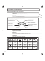
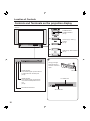
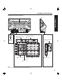
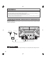
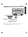
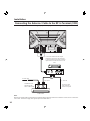
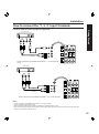
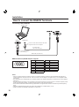
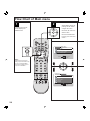
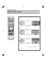
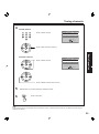
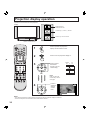
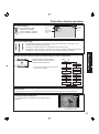
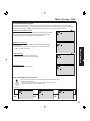
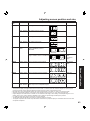
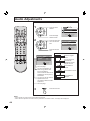
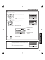
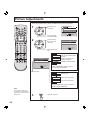
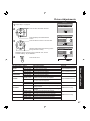
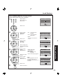
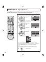
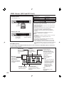
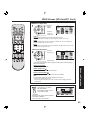
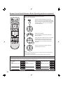
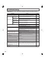
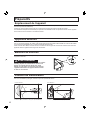
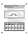
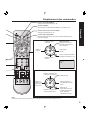
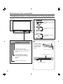
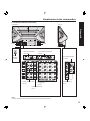
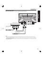
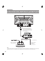
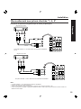
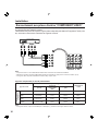
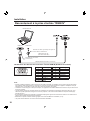
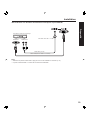
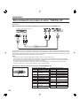
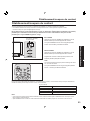
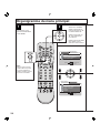
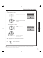
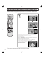
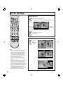
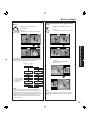
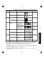
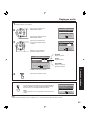
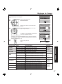
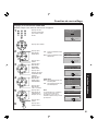
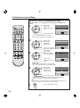
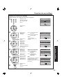
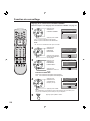
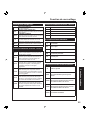
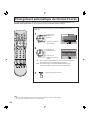
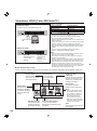
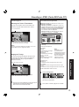
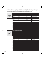
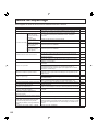
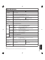
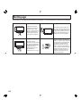
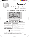
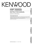
Installation
How to connect the RGB IN Terminals
Connecting a PC to RGB IN
COMPUTER
RGB OUT
AUDIO OUT
Connect a cable which matches the audio
output terminal on the computer.
PC audio cable
(M3 stereo mini pin)
Conversion adapter
(If necessary)
RGB cable (D-SUB 15P)
RGB IN Terminal (D-SUB 15P) Pin Layouts
11 12 13 14 15
6
7
1
8
2
9 10
3
4
Connection port view
5
Pin No.
1
2
3
4
5
6
7
8
Signal name
R
G
B
NC
NC
Ground for R
Ground for G
Ground for B
Pin No.
9
10
11
12
13
14
15
Signal name
NC
Ground
NC
NC
HD/CSYNC
VD
NC
NC: Not connected
Notes:
• Some PC models cannot be connected to the set. A conversion adapter is required to use the RGB cable (D-SUB 15P) to
connect a Macintosh computer to the set. There is no need to use an adapter for computers with PC / AT compatible D-SUB
15P terminal.
• The computer shown in the illustration is for example purposes only. Additional equipment and cables shown are not supplied
with this set.
• The picture will become dark if an PC signal with a vertical scanning frequency of 62 Hz is input. To obtain the optimum picture
quality with the projection display, a vertical scanning frequency of 60 Hz is recommended.
• Do not set the horizontal and vertical scanning frequencies for PC signals which are above or below the specified frequency
range.
• Select the desired RGB input position by pressing the PC/MENU or TV/VIDEO button. (P. 35)
• Similar connections are available at the RGB IN 1, 2 Terminals.
18