1
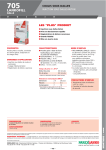
ONE PIECE
TUB SHOWER
INSTALLATION MANUAL
CUSTOMER SERVICE CANADA
1-800-387-0369
www.fiat.ca
ACRYLIC BATHWARE
PRE-INSTALLATION PLANNING
MODEL MTS 6032 - STANDARD WASTE AND OVERFLOW
MODEL MTS 6035 - STANDARD WASTE AND OVERFLOW
MODEL MTS 6200 - STANDARD WASTE AND OVERFLOW
MODEL MTS 377 - STANDARD WASTE AND OVERFLOW
The one piece tub/shower enclosures are designed for new
construction and must be within the installation locations before
framing is complete.
i nspecti on authori ti es requi rement. If fi re ra t ed walls ar e
specified, finished fire rated boards should be in place before
units are installed.
Protective plastic has been applied to the front face of the unit. It
is advised to leave this plastic on during installation to protect the
acrylic from scratchies. A protective piece of cardboard, about the
same size as the floor of the unit, should be cut from the
cardboard face cover and placed within the bottom of the unit.
The cardboard face cover should also be used after installation is
complete to protect the unit during the construction period.
Tools and materials required: (Other than standard plumbing
equipment)
Check and Verify All Dimensions
— Hole saws (sized for brass set)
— High speed drill
— 3/16” Drill bit
— Tape measure
— Level
— Shims
All plumbing and electrical shall be installed in accordance with
ROUGH-IN DETAILS - ALL MODELS
NOTE: Access must be provided to pump and/or generator.
Opening should be sufficient to install, repair or replace.
See drawing for access panel dimensions.
The framing procedure shown can be used with either wood or
metal studs:
NOTE: Wood inserts may have to be used to stiffen metal studs
supporting screw flange of unit.
4. Install plumbing tree within framing, by using measurements
from diagram. Measurements are taken from the front end of
the new studs that were installed to accommodate the screw
flange.
1. Before framing is started, check level and quality of floor, make
sure sub-floor is sturdy.
2. Rough-in 2 x 4 studs at standard room height to dimensions
shown. Check framed-in area for proper size and ensure
studding is straight, square and plumb.
5. Check plumbing for any leaks.
6. For steam units only - plumbing for the steam head must also
be completed before unit is installed, unless access panel has
been provided.
3. The studding across the top front of the unit can remain loose
or installed after installation of tub/shower unit if ceiling height
permits.
Installation is subject to regulation of the local inspection
authorities having jurisdiction.
NOTE: For whirlpool/steam models: The front corner studs may
have to be removed for installation. Replace the studs
when unit is in position. Also, studding will have to be
notched to allow clearance for whirlpool jets (see detail
drawing).
CAUTIONS: DO NOT LIFT WHIRLPOOL BY PIPING. CARE
MUST BE TAKEN TO AVOID DAMAGING WHIRLPOOL TUB BY
FORCING IT THROUGH TOO NARROW A STUD OPENING.
CARE MUST BE TAKEN NOT TO SUPPORT WEIGHT OF TUB
WITH DRAIN PIPE.
All statements, technical information, and recommendations contained herein are based on tests we believe to be reliable; but
the accuracy or completeness thereof is not guaranteed, and the following Is made in lieu of all warranties, expressed or
implied.
Neither seller nor manufacturer shall be liable for any injury, loss or damage, direct or consequential, arising out of the use of or
the inability to use the product. Before using, the user shall determine the suitability of the product for the intended use and user
assumes all risk and liability whatsoever in connection there with. No statement or recommendation contained herein shall have
any force or effect, unless it is in an agreement signed by officers of seller or manufacturer.
All whirlpool systems have been tested in-house before leaving the factory. Every system is tested under actual usage, ensuring
proper functioning of mechanical and electrical systems, resulting in many years of safe, trouble-free usage.
1
256000
ROUGH-IN DETAILS
MODEL
MTS 6032
MTS 6035
MTS 6200
B
A
58”
1473mm
59”
1499mm
59”
1499mm
B
C
88-3/4”
2254mm
87”
2210mm
88”
2235mm
87-1/4”
2216mm
86-1/4”
2191mm
86-1/2”
2197mm
D
31”
787mm
36”
914mm
31”
787mm
E
16-13/16”
427mm
13”
330mm
15-1/2”
394mm
C
WHIRLPOOL
UNITS ONLY
NOTCH
1 in x 12 in
(25mm x 305mm)
MINIMUM
16 in x 14 in
(406mm x 356mm)
WHIRLPOOL
PUMP ACCESS
6 in x 11 in
(152mm x 279mm)
E
A
(15 61 in
49
mm
)
D
MTS 6032
MTS 6200
ROUGH-IN DETAILS MTS 377 SERIES
71"(1803)
36"
(915)
10"
(254)
20"
(508)
DRAIN
JETS (8)
65 1/4" (1657)
88 3/4"
(2254)
3"(76)
49 1/4"
(1251)
41 1/4"
(1048)
21 3/4"
(552)
20"
(508)
OVERFLOW
73 3/4"(1873)
2
256000
INSTALLATION PROCEDURE
1. Referring to the faucet manufacturer’s instructions, mark and
drill pilot holes for the plumbing fixtures. Use the recommended
hole-saw size and cut the openings from the finished side of the
unit.
WARNING: When using electrical products, basic precautions
should always be observed, including the following:
1. DANGER: RISK OF ELECTRIC SHOCK! Connect to a circuit
protected by a ground-fault circuit interrupter (GFCI).
2. Install the drain and overflow according to the manufacturer’s
instructions and use a mildew resistant silicone to seal the
underside of the drain to the tub.
2. Grounding is required. The unit should be installed by a
licensed electrician and grounded.
3. Permit access for motor servicing.
3. Refer to the Electrical Installation Instructions below for units
equipped with whirlpool, bubbler, or steam units.
4. All building materials and wiring should be routed away from
the pump body and heater (if equipped).
NOTE: Whirlpool or Bubbler components are factory installed
must not be modified or relocated. Unauthorized modifications to
factory installed components will affect system performance and
functionality. FIAT AND AMERICAN STANDARD BRANDS WILL
NOT BE LIABLE UNDER ITS WARRANTY OR OTHERWISE,
FOR PERSONAL INJURY OR DAMAGED CAUSED BY ANY
UNAUTHORIZED MODIFICATION.
Each component (whirlpool, bubbler, etc) requires its own
dedicated 120VAC 15A 60Hz GFCI protected circuit.
Prior to use, ensure the ground-fault circuit interrupter(s) are
tested and operational. Any malfunctions found must be repaired
prior to operation of the unit.
4. Carefully position the unit into the rough opening until the
flanges are flush to the framework.
5. Shim the unit until level horizontally and vertically. Shims
should be placed under the sump support board and nailed or
glued in place if possible (DIAGRAM A).
NOTE:
W AT E R T E S T I N G F O R A L L P I P I N G J O I N T S A N D
CONNECTIONS SHOULD BE PERFORMED PRIOR TO
COMPLETING INSTALLATION. BEFORE WATER TESTING
ANY WHIRLPOOL MODELS, CLEAN UNIT THOROUGHLY
OF ALL DIRT AND DEBRIS. FILL UNIT WITH WATER TO
A LEVEL 1 1/2” (38 mm) BELOW OVERFLOW BEFORE
STARTING WHIRLPOOL PUMP.
6. Drill 4, 3/16” holes on side and top flanges and fasten unit with
#6 x 1½” wood or drywall screws. DO NOT OVERTIGHTEN.
7. Finish the front of the unit with drywall (DIAGRAM B).
CAUTION:
ELECTRICAL INSTALLATION INSTRUCTIONS
NEVER START PUMP UNLESS TUB IS FILLED WITH WATER
TO LEVEL DESCRIBED IN NOTE ABOVE.
All wiring must be performed by a licensed electrician in
accordance with the national electrical code and all other
applicable codes.
After installation is complete, use the shipping cover to protect
the unit.
DIAGRAM A
DIAGRAM B
3
256000
CLEANING AND CARE OF ACRYLIC BATHWARE
Acrylic bathware is molded of colorfast acrylic to provide a thick,
smooth, super strong surface. It is reinforced with fiberglass for
years of durable service.
application of liquid or automotive car wax. If the unit has been
damaged in any way, contact your local distributor for local repair
service.
The protective plastic film applied to the unit will leave a film upon
the acrylic. To remove this film, use a soft cloth dampened with
rubbing alcohol or turpentine and wipe the area clean.
NOTE:
Whirlpool System must be flushed every 90 days as follows: Fill
the bath with hot water only. Add to hot water 2 teaspoons low
foaming dish washing detergent such as Cascade or Calgonite.
Run the whirlpool for 10 to 15 minutes. Drain the bath completely.
Fill the bath with cold water only. Run the whirlpool for 5 to 10
minutes. Drain bath completely.
NEVER USE ABRASIVE CLEANERS UNDER ANY
CIRCUMSTANCES!
For day to day cleaning, use only liquid or foam cleaners with a
soft cloth.
WARNING: Soap and water should only be used for the cleaning
of the decorative screened glass. Avoid any cleaning agents
labelled with a corrosive warning sign.
Dull area may be restored or light scratches removed, by rubbing
with an automotive rubbing compound, followed by a light
CUSTOMER SERVICE CANADA
1-800-387-0369
www.fiat.ca
4
256000
NETTOYAGE ET ENTRETIEN
Les baignoires en acrylique sont moules en acryliques de couleur
qui offre une surface epaisse, douche et tres robuste. Renforce
de fibre de verre, ce materiau assurere une grande durabilite.
Le pellicule protectrice en plastique recouvrant le bain laissera un
film sur l’acrylique. Pour enlever ce film, essuyer la surface a
l’aide d’un chiffon doux humecte d’alcool à friction d'essence
minerale ou de terebenthine.
N’UTILISEZ JAMAIS, EN AUCUNE CIRCONSTANCE, DES
AGENTS DE NETTOYAGE ABRASIFS.
Pour le nettoyage régulier, utiliser seulement nettoyants liquids ou
moussants avec un linge doux.
L e s zo n e s te r n e s p e u t ê t re re s ta u ré e t d e s p e t i te s ray u re s
peuvent être supprimées par frottement avec une pâte à polir
pour automobile, suivi par une application légère de cire liquide
ou pour voitures. Si l’appareil a été endommagé contactez votre
distributeur ou service de réparation local.
NOTE:
La systeme de tourbillion doit etre doivent être soigneusement
nettoyés chaque 90 jours de la manière suivante: Remplis le bain
a ve c d ’ e a u c h a u d e . A j o u t e r 2 c u i l l è r e s à c a fé d e s a vo n à
vaisselle qui mousse peu comme le Cascade ou Calgonite.
Actionnez les jets et faites fonctionner pendant 10 à 15 minutes.
Vider complètement le baignoire. Remplissez le baignoire
seulement avec de l'eau froide. Actionnez les jets et faites
fonctionner pendant 10 à 15 minutes. Vider complètement le
baignoire.
AVERTISSEMENT : L'eau et du savon doivent etre uiliser pour la
nettoyage de la verre decorative. Ne pas nettoyer l'appareil avec
des matériaux abrasifs ou corrosifs.
Centre d'assistance à la clientèle :
1-800-387-0369
www.fiat.ca
256000
4
MODE D’INSTALLATION
1. Marquez la position et percez les trous de guidage pour les
robinetteries, selon les instructions du fabricant de la robinet.
Couper les ouvertures de la côté fini de la produit en utilisant le
taile de trou reccomandé.
2. Installer le renvoi de vidange et trop-plein selon les instructions
du fabricant et utiliser du silicones résistant aux moisissures
pour sceller le dessous de la drain à la baignoire.
3. Se reporter au manuel d'instructions pour les produits équipé
avec tourbillon, barboteur, ou appareil à buée.
AV E RT I S S E M E N T: L o rs q u e vo u s u t i l i s e z d e s a p p a re i l s
électriques, vous devez toujours prendre des précautions de base
afin, y compris la suivante :
1. ATTENTION: RISQUE DE CHOCS ÉLECTRIQUES! Se
raccorder à un circuit protégé par un disjoncteur différentiel de
fuite à la terre (DDFT).
2. La mise à la masse est requise. Il est recommandé que cet
appareil devrait être installé par un un électricien qualifié.
3. Accorde l'accès pour la service du moteur
NOTE:
4. Abaissez doucement la baignoire dans l'ouverture brute jusqu'à
ce que les brides s'alignent avec le cadre.
Avant utilisation, vérifiez que le(s) disjoncteur(s) différentiel de
fuite à la terre (DDF T) sont testé et opérationnel. Les
dysfonctionnement doivent être réparer avant utilisation.
NOTE: Les composants de les tourbillons ou barboteur sont sont
i n s ta l l é s e n u s i n e e t n e n e p e u ve n t p a s ê t re m o d i fi é e s o u
délocaliser. Le performance et fonctionnalités de la système
seront affectée par les modifications non autorisées. FIAT ET
A M E R I C A N S TA N D A R D S E R A D É G A G É E D E T O U T E
OBLIGATION QUANT AUX RECOURS À LA GARANTIE ET NE
POURRA ÊTRE TENUE RESPONSABLE DE DOMMAGES OU
B L E S S U R E S C A U S E PA R L E S M O D I F I C AT I O N S N O N
AUTORISÉES.
5. Poser des cales pour assurer son aplomb. Les cales doivent
être placer sous le support du puisard et clouer ou coller si
c’est possible (Figure A).
6. Percer 4 trous de 3/16po sure les brides de les cotés et dessus
et fixez l’unité avec des vis à plaque de plâtre ou des vis à
bois. NE SERREZ PAS EXCESSIVEMENT. OVERTIGHTEN.
7. Utlisez des plaques de plâtre pour recouvrant le devant de la
baignoire. (FigureB)
Les Instrusctions D’Installations électriques
L'installation du filage doit être faite par un installateur qualifié et
doit respecter tous les règlements électrique nationaux et tous
autre codes applicables.
4. Tous les matériaux de construction câbles doivent être éloigné
de le corps de la pompe et le radiater (le cas échéant).
Chaque composantes (tourbillons, barboteur,etc) requiert sa
propre circuit protegé (120VAC 15A 60Hz DDFT)
T O U S L E S J O I N T S D E L A C A N A L I S AT I O N E T L E S
CONNECTIONS DOIVENT ÊTRE TESTÉS POUR DES FUITES
AVANT D’VOIR COMPLETE L’INSTALLATION. NETTOYEZ ET
E N L E V E Z L E S D É B R I S AVA N T AVA N T L E S T E S T S
D'IMPERMÉABILISATION.REMPLISSEZ AVEC D’EAU 1.5PO
SOUS LE NIVEAU DE TROP-PLEIN AVANT D’ACTIONNER LA
POMPE DE TOURBILLON.
ATTENTION :
NE COMMENCEZ JAMAIS LE POMPE SAUF SI LA BAIGNOIRE
EST REMPLIT D’EAU A LA NIVEAU DÉCRITES DANS LA NOTE
CI-DESSUS.
Après l'installation du système, utilisez le couverture de transport
pour protéger l'appareil.
support du puisard
DIAGRAMME A
Cale
2 x 4 Normale
2 x 4 Normale
3/8 po
(10 mm)
3/8 po
(10 mm)
plaques de
plâtre
plaques de
plâtre
DIAGRAMME B
256000
3
B
ROUGH-IN DETAILS
MODÉLE
MTS 6032
MTS 6035
MTS 6200
A
58 po
1473 mm
59 po
1499 mm
59 po
1499 mm
B
88-3/4 po
2254 mm
87 po
2210 mm
88 po
2235 mm
C
87-1/4 po
2216 mm
86-1/4 po
2191 mm
86-1/2 po
2197 mm
D
31 po
787 mm
36 po
914 mm
31 po
787 mm
E
16-13/16 po
427 mm
13 po
330 mm
15-1/2 po
394 mm
C
POUR MODULES
DE BAIN-TOURBILLON
ENTAILLER
1 po x 12 po
(25 mm x 305 mm)
6 po x 11 po
(152 mm x 279 mm)
E
A
(15 61 p
49 o
mm
)
PANNEAU D’ACCÉS
MINIMUM DE
16 po x 14 po
(406 mm x 356 mm)
REQUIS POUR
POMPE DE BAIN
TOURBILLON
D
2 x 4 Normale
2 x 4 Normale
3/8 po
(10 mm)
3/8 po
(10 mm)
plaques de
plâtre
MTS 6032
MTS 6200
ROUGH-IN DETAILS MTS 377 SERIES
plaques de
plâtre
71 po(1803)
36 po
(915)
10 po
(254)
20 po
(508)
RENVOI
JETS (8)
65 1/4 po (1657)
88 3/4 po
(2254)
49 1/4 po
(1251)
3 po (76)
41 1/4 po
(1048)
21 3/4 po
(552)
PANNEAU D’ACCÉS MINIMUM
DE 16 po x 14 po (406 mm x 356 mm)
REQUIS POUR POMPE DE BAIN
TOURBILLON
20 po
(508)
DÉBORDEMENT
73 3/4 po(1873)
256000
2
ÉQUIPEMENTS DE SALLE DE BAIN EN ACRYLIQUE
PRÉPARATION PRÉLIMINAIRE
MODÈLE MTS 6032 - TROP-PLEIN ET BONDE STANDARD
MODÈLE MTS 6035 - TROP-PLEIN ET BONDE STANDARD
MODÈLE MTS 6200 - TROP-PLEIN ET BONDE STANDARD
MODÈLE MTS 377 - TROP-PLEIN ET BONDE STANDARD
Les bains-douches monobloc sont conçus pour être intégrés â
une nouvelle construction et doivent être en place avant que la
charpente ne soit terminée.
La face avant du bain est recouverte d'une pellicule protectrice
en plastique. Il est conseillé de garder ce plastique en place
p e n d a n t I ' i n s ta l l a t i o n d u b a i n év i te r d e raye r I ' a c r y l i q u e.
Découpez, dans Ie panneau avant du carton d'emballage, une
pièce aux dimensions du dessous du bain; puis déposez la pièce
dans Ie fond du bain. Le panneau avant du carton servira aussi à
protéger Ie bain, une fois installé, tout Ie temps que durera la
construction.
exigences des autorités d'inspection.
Les outils et les matériaux nécessaires (outre Ie matériel courant
de plomberie) sont:
— une perceuse àgrande vitesse
— 3/16” Drill bit
— une ruban à mesurer
— un niveau
— des scies emporte-pièces
— des cales
Vérifiez toutes les dimensions.
La plomberie et I'électricité doivent être montées selon les
PLOMBERIE BRUTE - TOUS LES MODÈLES
La charpente illustrée peut etre faite en bois ou en métal :
NOTE : II faudra peut-être renforcer les poteaux métalliques qui
supportent la bride filetée au moyen de pièces de bois.
1. Avant de båtir la charpente d'appui, vérifiez Ie niveau et I'état
du plancher; assurez-vous que Ie faux-plancher est solide.
2. Taillez les montants à la hauteur normale de plafond selon les
cotes indiquées. Vérifiez les dimensions de I'espace charpenté
et assurez-vous que les montants sont droits, d'équerre et
d'aplomb.
3. Les montants en travers de la partie avant supérieure de bain
n'ont pas à être maintenus en place et peu-vent même être
fixés après I'installation du bain-douche si la hauteur du
plafond Ie permet.
NOTE: Bain-douche de vapeur et bain tourbillon: II faudra peut-être
enlever les montants du coin avant pour procéder a
I'installation du bain. Remettez en place les montants
lorsque Ie bain est installé. II faudra aussi entailler les
montants pour laisser I'espace libre nécessaire aux
gicleurs du système tourbillon (voir Ie dessin des détails).
NOTE: II faut prévoir un accès à la pompe et/ou au générateur.
L'ouverture pratiquée doit être suffisamment grande pour
permettre d'installer, de réparer et de remplacer ces
deux appareils. Dimensions du panneau de visite: voir
dessin.
4. Installez Ie tuyau de distribution à I'interieur de la charpente
d'appui en vous reportant aux cotes du schéma. Les mesures
sont prises depuis la partie avant des nouveaux montants
installées pour servir d'appui à la bride filetée.
5. Vérifiez qu’il n’y a aucune fuite dans la plomberie.
6. Bains-douches de vapeur - la plomberie du système de
vapeur doit être terminée avant que le bain ne soit installé sauf
si un panneau de visite permet d’avoir accès à l’installation.
L’installation est soumise aux règlements des autorités inspection
locales compétentes.
ATTENTION : NE PAS SOULEVER LE BAIN PAR LES TUYAUX.
E V IT E R D’ E N D O M M AG E R L E BA I N TO U R B I L LO N E N L E
F O R CA N T DA N S U N E O U V E RT U R E T RO P E T RO IT E
LORSQU’IL EST INSTALLE EN ALCOVE. NE PAS LAISSER LE
POIDS DU BAIN REPOSER SUR LE TUYAU D’ECOULEMENT.
Bien que toutes les affirmations, informations techniques et recommandations du présent texte soient basées sur des essais que no us jugeons
fiables, I'exactitude et I'exhaustivité de celles-ci ne peuvent être assurées. Ce qui suit annule et remplace donc toute garantie explicite ou implicit.
Ni Ie vendeur ni Ie fabricant ne peut être tenu responsable d'une blessure, du'une perte ou d'un dommage, directs ou indirects, provenant de
I'utilisation du produit ou de I'impossibilité de I'utiliser. Avant d'utiliser Ie produit, I'utilisateur doit déterminer si celui-ci convient a I'usage prévu.
L'utilisateur assume tous les risques et responsabilités concernant ledit produit. Aucune affirmation ni recommandation contenue dans Ie
présent texte n'a de valeur ni d'effet sauf si contenues dans une entente signée par les représentants officiels du vendeur ou du fabricant.
Tous les systèmes tourbillon ont été mis à I'essai en usine avant d'être expédiés. Chaque système est soumis à un essai d'utilisation réelle visant
à assurer Ie bon fonctionnement des dispositifs mécaniques et electriques ainsi que de nombreuses années d'utilisation sûre et sans problème.
256000
1
BAIN-DOUCHE
MONOBLOC
MANUEL D’INSTALLATION
Centre d’assistance à la clientèle:
1-800-387-0369
www.fiat.ca
256000