1
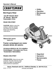
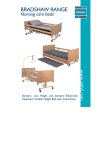
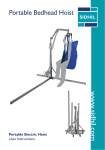
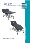
BRADSHAW RANGE
Nursing care beds
www.sidhil.com
Bariatric, Low Height and Standard Electrically
Operated, Variable Height Bed User Instructions
Thank you for choosing a Bradshaw Nursing Care Bed. This user manual should be
read carefully before you use your bed, as it contains important information regarding
safe operation and maintenance in order to provide reliable service.
Please ensure that you understand all the instructions thoroughly, and if you have any
questions concerning operation and maintenance please contact your supplier who will
provide you with expert professional advice.
In line with our policy of continuous improvement we welcome any suggestions that
could lead to product improvement.
This product is manufactured to comply with the essential requirements of
the Medical Devices Directive 93/42 EEC
Contents
Section
1.
2.
3.
4.
5.
6.
7.
8.
9.
10.
11.
12.
13.
Title
Introduction
Parts Identification
Specifications
Assembly & Preparing for Use
Operating the bed
Fitting the Siderails & Lifting Pole
Disassembly for storage or travel
Bradshaw Pump Bracket
Using your bed: Do’s & Don’t’s
Care & Maintenance
Fault Diagnosis
Accessories
Warranty
2
Page
3
4
5
6
11
14
15
17
18
19
19
20
21
1. Introduction
Your Bradshaw Nursing Care Bed is intended for use within a Nursing Home or
domestic environment. It is designed to provide users with optimum independence
and freedom of movement, operated via a touch button control handset, allowing the
occupant to select positioning as required.
The Bradshaw bed range is manufactured as a sturdy steel design and is coated in a
durable powder coated finish. When connected to the domestic mains supply,
actuators at each end allow the mattress platform to be positioned at variable heights.
The platform may also be tilted head up or foot up by operating the appropriate
handset control. Two further actuators beneath the platform allow full profiling
capability of the backrest and knee break features*. The handset control may be
‘locked’ by the carer to prevent operation by the bed occupant†.
The bed comes complete with full length wood effect side rails.
The Bradshaw bed mattress platform is available in either wooden or steel slats or
mesh. The Bradshaw Low mattress platform is fitted with matching wooden trim to fit
into a domestic environment. The Bariatric version is only available with metal slats
Your Bradshaw bed comprises a number of manageable parts that can be assembled
and disassembled with the minimum amount of effort. A transport stand enables the
bed to be stored and moved about very conveniently.
For the Bradshaw Low, the exceptionally low height of the platform at 195mm in its
lowest setting makes the bed safe for use without side rails when used in conjunction
with a crash mat.
* Backrest only for 2 section mesh bed.
† Not available for 2 section mesh bed.
3
2. Parts Identification
(Bed shown Bradshaw Low)
Adjustable Siderails
11 Locking Castors
Lifting Pole +
12 Height Adjustment Actuator
Head End
13 Anti pullout clip (Handset version 1)
User Handset (Handset version 1)
14 Bed Extension (Accessory)
15 User Handset (Handset version 2)
Siderail Release Button
(Head End)
16 User Handset
(Handset version 1: 1275/MESH/2)
Rising Backrest
17 Anti pullout clip (Handset version 2)
Backrest Actuator
+ Not available for Bariatric nor 2 section
Kneebreak Actuator
mesh
Electric Kneebreak *
*
Not available for two section mesh
Siderail Release Button
1
2
3
4
5
6
7
8
9
10
1
4
2
3
13
5
6
14
7
8
9
10
11
12
15
16
17
4
3. Specification
Overall length
2220mm (Low) 2140mm (Standard) 2235mm (Bariatric)
Overall width
1050mm (Low and Standard) 1360mm (Bariatric)
Patient surface length
2000mm (All Beds)
Patient surface width
900mm (Low and Standard) 1150mm (Bariatric)
Height adjustment (Low)
195mm-590mm (7.5”-23.2”)
Height adjustment (Standard)
390-790mm (15.35”-31.1”)
Height adjustment (Bariatric)
420-815mm (16.5”-32”)
Backrest angle
75° (Low and Standard) 70° (Bariatric)
Knee break angle*
35° (Low and Standard) 20° (Bariatric)
Tilt
11° head down 11° foot down
Safe working load
180kg (28 stone) Low & Standard 318kg (50 stone) Bariatric
Section weights
Head end
Foot end
Head end platform
Foot end platform
Metal/Wood Slats
20.5kg
20.5kg
24.5kg
24.5kg
Actuator rating
IP 54
Electric shock protection
Class 2, Type B
Voltage in
Current in Max 3 amp
Voltage out
Duty rating
230V AC ±10%, 50Hz
Bariatric
37.0kg
34.0kg
38.0kg
38.0kg
24V DC
Intermittent 10% 6 mins per hour
*Not available on 1275/MESH/2
5
Mesh
20.5kg
20.5kg
24.0kg
11.5kg
4. Assembly & Preparing for Use
Before attempting to assemble this product ensure the instructions have been
read and fully understood. If this is the first time you have used this product it may
be advisable to assemble the bed with the aid of a second able-bodied person. A
4mm allen key is supplied with each bed (5mm with the Bariatric). Take care
when separating individual parts of the bed as some parts are of considerable
weight. You may find it helpful to apply the brake on the castors before unpacking
the bed. The procedure is as follows:
NB: Two people required for the Bariatric Bed assembly.
1.
2.
3.
4.
5.
6.
Clear the area intended for the bed of any obstacles and ensure it is a level surface.
Lock both castors on one end section, loosen the hand wheel, or grub screw with
the supplied allen key. Lift each mattress section vertically and remove.
Note that the bed end sections are identical and interchangeable (see fig 1).
Release the brakes and remove the two hand wheels on one bed end. While
supporting both panels carefully pull the two ends apart.
Remove the hand wheels from the other end and remove the two transport
brackets. Safely store the transport bracket for future use.
Save the four hand wheels that held the bed ends as these are required later.
(Note the Bariatric bed is supplied with all the required fittings, none need to be reused)
Cut off the plastic retaining ties from the head and foot mattress sections.
FIG 1
6
7.
Slide the footend mattress platform section onto the spigots and lean both parts
down so that the other end of the platform section rests gently on the floor. (See
Fig 2).
FIG 2
Spigot
Footend
mattress
platform
section
8.
Take two dome head screws (supplied) and screw them into the slots at each
side. Do not fully tighten either at this point. (See Fig 3). Screw four grub screws
into the underside of the platform section. Do not fully tighten either at this point.
(See Fig 3)
FIG 3
Dome Screw
Grub Screw
7
9. Follow the same procedure for the backrest and head end.
10. Release the brakes on all four castors. Lift the centre ends of each section and
move them together, locating the spigots into the opposing side tubes and pulling
the two sections together. (See fig 4 below). Once the sections are fully located,
the grub screws beneath the side tubes should be fully tightened using the 4mm
allen key, (5mm for the Bariatric Bed). It is helpful during this operation to lift the
centre of the bed so that its weight is not pressing down on the grub screws until
they come up tight.
11. The four dome screws and grub screws at each corner of the bed (inserted in
steps 8 and 9) should now be fully tightened to make the bed rigid. Tighten the
grub screws first, followed by the dome screws. Again it is helpful during this
operation to tilt the bed ends to take the weight off the screws as they are
tightened.
12. Re-apply the brakes, at the head end of the bed only.
13. The actuator and handset leads can now be fitted into the control box. The bed
has two types of control boxes either version 1 or version 2. If supplied with
version 1 go to step 14 and if supplied with version 2 go straight to step 15. The
versions can be identified through the handsets within the parts identification list
in section 2.
14. Ensure the plugs are pushed firmly home into the correct sockets (see fig 5), as
highlighted by the label on the control box. Correct orientation of the plugs into
the sockets
FIG 4
FIG 5
8
FIG 6
Clip
Clip
Anti pull out guard
The control box has five ports of which two already contain plugs when the bed is
delivered. Working away from the port nearest to the actuator, (see fig 5)
connections are as follows:1 - Backrest actuator
2 - Knee break actuator (Blanking plug on 1275/MESH/2) HB - Handset
3 - Head end lift actuator
4 - Foot end lift actuator
HB – handset port
14a.
Attach the anti pull out guard to the control box, by clipping in place ensuring
the wires are not trapped (see fig 6).
15.
Ensure the plugs are pushed firmly home into the correct sockets.
(See Fig 7 below) Correct orientation of the plugs into the sockets is
necessary as they will only fit one way round.
FIG 7
9
The control box has seven ports of which three already contain plugswhen the bed is
delivered. Working away from the port nearest to the motor, (see Fig 7) connections
are as follows:port 1 Blanking plug port
port 3 Backrest Actuator port
port 5 Head end lift actuator port
port 7 No Connection
2 Handset
4 Kneebreak actuator
6 Footend lift actuator
15a.
Attach the anti pull out guard to the control box, by clipping in place
ensuring the wires are not trapped (see fig 8).
FIG 8
16.
Anti pull out guard
The bed can now be manoeuvred into its correct position and plugged into
the mains supply.
WARNING
Check that the transit-retaining straps have been removed from
the rising backrest frame and knee break frame. Operating the
bed with these straps in place will damage both the actuators and
framework of the bed.
WARNING
This bed must only be used with a mains supply of 240V 50Hz. If
you wish to use this product outside of the UK seek professional
advice as to the compatibility of this product with the mains
power supply type.
10
5. Operating the Bed
The Bradshaw Bed is supplied with 1 of 2 easy to use handsets (Version 1 - Fig 9,
Version 2 section 5.1), which allows the mattress platform to be raised or lowered at
a safe rate. The handset can either be operated by the occupant or by an attendant. If
an attendant is operating the bed ensure the occupant is aware in advance of each
action taking place. Carry out each action in a smooth and controlled manner.
1.
Use the indicated buttons on the handset to adjust the angle of the backrest.
The backrest should not be used as a means of lifting the occupant.
2. Use the appropriate buttons on the
handset to adjust the angle of the
knee break (not available for the
1275/MESH/2). Once the knee break
has been set at the desired angle, the
leg rest angle can be set by lifting and
releasing this section manually on the
ratchet.
3. An auto contour function is also available (except on 1275/MESH/2); this
alters both the backrest and knee break. To set the contoured position press
the button on the handset indicated with the arrow pointing upwards, and
keep pressed until the desired position is reached.
4. To raise the mattress platform press the button on
the handset indicated with the arrow pointing upwards, and keep pressed
until the desired height is reached.
5. To lower the mattress platform press the button on the handset indicated
with the arrow pointing downwards, and keep pressed until the desired height is
reached.
6. If forward or reverse tilt (Trendelenburg) of the bed is required, this can be
accomplished using the Forward/Reverse tilt buttons.
Note: When putting the bed into reverse tilt, ensure the bed end does not clash with
the wall.
IMPORTANT: Ensure the occupant is away from the sides of the bed a
cannot fall when adjusting the mattress platform position.
11
FIG 9 - Diagram of Linak handsets
Backrest
Backrest
Knee break
Platform height
Auto
contour
Forward/Reverse
tilt
Platform Height
Forward/Reverset tilt
Lockable Handset
Lockable Handset
The handset enables the carer to lock out any or all of the functions on the bed (not
available on 1275/MESH/2).
To lockout a function:
1. Insert the key (supplied with handset) into the receptacle in the centre
of the desired buttons.
2. Turn the key clockwise. The key should
now be pointing towards the
FIG 10
closed padlock symbol; the indicator
now be yellow (see fig 10).
3. The function is now locked out.
To unlock a function:
4. Insert the key (supplied with handset)
into the receptacle in the
Indicator
centre of the desired buttons.
5. Turn the key anticlockwise. The key
should now be pointing
upwards; the indicator will now be green.
6. The function is now unlocked.
12
Key
Open
Padlock
(unlocked)
5.1
Version 2 - The Bradshaw Version
When power is connected, the power LED lights and stays lit while power is
present. To enable the handset functions, it is necessary to swipe the magnet across
the LED with a padlock symbol which then lights indicating that the handset will
operate the bed. (shown in Fig 11 below)
Swiping the magnet across this LED again locks all functions. This is useful if the carer
wishes to prevent unauthorized re-positioning of the bed. In this case it is possible to
remove the magnet on its key ring from the handset. However unlocking of functions
will then only be possible by the carer bringing the magnet on each visit to the bed.
FIG 11
Function LED
Backrest
Magnetic slide
Knee break
Full profiling
Platform height
Magnetic key
Trendelenburg
Reverse - Trendelenburg
Power On-LED
LED mode
Magnetic lock symbol (switching range)
13
6. Fitting the Lifting pole and Side rails
Lifting pole
1. The lifting pole slots into the socket at either side of the head end of the mattress
platform. Ensure the pin at the base of the pole locates into the groove in the
socket so that the pole may not twist. (Lifting pole not available on the Bariatric,
or two section mesh beds)
2. Loop the lifting triangle over the pole, ensuring that the strap is located between
the pins so that it cannot slip down.
Side Rails
1. The side rail sliding mechanisms are pre-fitted into the channels on the bed ends.
Depressing the black button allows this mechanism to be lowered to the bottom
position (see fig 12).
2. Lower the bed to the lowest height. Press each black button and lower both
sliding mechanisms. At one end only remove the screw which prevents the
mechanism from falling out of the channel, and carefully remove all parts from the
channel at one end of the bed (see fig 13).
Correct assembly according to procedure is necessary to ensure that the top rail
can be lowered to a position below the mattress surface.
FIG 13
FIG 12
Plastic spacer
block
Button
Fingers
Wire Loop
Spacer block
3.
Please note:
Pointed ends to
top
Bariatric
assembly - as
per standard
(shown above)
but with a
different spacer
Take two wood side rails and locate them onto the fingers that were not removed.
Ensure the curved sides of the rails face upwards. The free ends of these rails should
rest on the floor close to the removed parts.
Important: Ensure the fingers and wire loop are assembled as shown in fig 13
14
4.
5.
6.
7.
8.
Take the previously removed upper pair of fingers (and wire) and push them into
the holes in the end of the side rail. Lift the slider up into the channel, ensuring
that the wire loop also slides up inside the channel. It is recommended that a
second person holds the rail at this point.
Take the second pair of fingers. Ensure the top finger is located in the bottom hole
in the wire loop (see fig 15). Push both fingers into the holes in the end of the
second side rail.
Lift the assembly further up into the channel, ensuring that the plastic spacer block
is located between the two sliders (see fig 15). Lift up until it clicks into place
above the black button.
Replace the screw removed in step 4.
Repeat this operation for the other side of the bed.
Lowering the side rails
In order to lower the rails, it is essential to first lift the top rail slightly allowing the black
button to be depressed. Always lower them gently to the bottom stop. Never simply
allow them to fall as this will damage the bed.
7. Disassembly for storage or travel
Before disconnecting from the mains supply, first lower the bed to its lowest height and
second adjust the mattress platform to the fully flat position. (This will enable packaging
onto the transport stand and also prevent damage to the side rail mechanisms during
dismantling)
To disassemble your bed, follow section 4 in reverse sequence, taking care when
separating the individual parts as some parts are of considerable weight.
Before removing any actuator leads, or if dismantling the bed for storage or transport,
it is recommended that the leads are disconnected from the main control box.
However, the anti pull out guard will need to be removed first. A small flat bladed
screwdriver is required. Using the screwdriver, carefully bend the locking tab inwards
(see fig 14, only version 1 shown) Once released, ease out to locking tab on the
opposite side. The clip may then be lifted free and the plugs disconnected.
NB: Bariatric bed requires two people for disassembly
15
FIG 14
Ensure all parts are safely stored and parts are not damaged or lost. If the bed is to be
stored on its transport stand, fit both of the brackets to one of the bed ends and tighten
the hand wheels. Then fit the other bed end onto the transport stand and again tighten
the hand wheels.
FIG 15
The mattress platform sections are now lifted and placed down over the relevant
locations on the brackets (see fig 15). Ensure the backrest section is placed on the stand
first. It may be necessary to remove the actuator clevis pin to make room for the knee
break section to slide down fully.
Ensure all grub screws and hand wheels are tight.
16
8. Bradshaw Pump Bracket
Bracket Fitting Instructions
1. Hold the bracket in the correct orientation, with the horizontal ‘W’ shaped part to
the outside (curved side) of the bed end.
2. Offer the bracket up to the top-centre of the bed end. Locate the horizontal ‘W’
shaped side of the bracket to the curved side of the bed end, before pushing the
two legs down the inside.
3. Check bracket position, the two legs should be equal distance from the logo
on the inside of the bed end, as per images below:
Pump Fitting Instructions
Note. Always fit the pump after correctly fitting the bracket
1. Small diameter pump hooks with 90 degree bend:
a. Pull the hooks out until they are approximately 1 inch (25mm) apart.
b. Lower the two hook ends into the ‘V’ in the middle of the bracket as per images:
c. Allow the bottom of the pump to sit against the outside of the bed end.
d. Ensure the two horizontal legs are flush with the top of the bed end by
pushing down on them.
2. Fit larger curved pump hooks using the above method, however the curved hooks
must be opened out to locate in the outer parts of the bracket, as per the image below:
Outer location
points
17
8. Do’s & Don’ts
Do check for obstructions before raising and lowering the bed
Do ensure the bed is cleaned on a regular basis.
Do ensure the bed is inspected on a regular basis (minimum once yearly service).
Do ensure that all the control plugs are pushed home firmly.
Do ensure the mains lead is plugged into the mains supply.
Do ensure that the grub screws and hand wheels are tight so that the bed remains rigid in use.
Do Not exceed the safe working Load of 180kg (28 stone, Standard and Low) 315kg
(50 Stone, Bariatric)
Do Not use the rising backrest feature to lift the occupant
Do Not allow children to play with the Bed.
Do Not use the bed if an actuator makes any unusual noises, smells or becomes
excessively hot.
Do Not store items under the bed
Do Not allow any part of the bed or mattress to become in contact with any naked
flame or excessive heat sources.
Do Not use a mobile hoist with the bed in its low position as there is insufficient
clearance between floor and actuators. Damage caused to actuators in this
manner is outside the warranty on the product.
Do Not use the bed electrical system for longer than 2 minutes without an 18 minute
period of rest, failure to observe this limit will result in irreparable damage to the
system control box that will not be covered by the manufacturers warranty.
18
9.
Care & Maintenance
Cleaning
All surfaces to be wiped down with a soft cloth moistened with a mild detergent and
diluted in hot water. Extra care should be taken around areas where excess dirt or dust
may gather. Rinse down with clean water and dry off with a paper towel.
If any infectious material(s) have been in contact with the bed or it has been used by a
patient with a known infection, the above procedure should be followed by an
additional clean by wiping down with a damp cloth soaked in Sodium Hypochlorite
solution (1000 ppm available chlorine) and dried with a clean dry cloth.
Always ensure that cleaned parts are allowed to dry before putting the mattress back
in place.
WARNING
Before cleaning, disconnect mains lead from the powersupply
Maintenance
The Bradshaw bed is designed to require very little maintenance, however if there are
any signs of damage, or the bed is not performing as it should, then please contact your
supplier for further assistance. Any maintenance should only be carried out by suitably
trained personnel.
10. Fault Diagnosis
The Bradshaw bed is designed to give long and reliable service. If however a fault does
occur please try the following suggestions before calling your supplier for assistance, as
these may help in diagnosing the fault.
Check that the mains lead is connected to the mains supply and this is switched on.
Check the fuse in mains plug.
Check that the Handset is not in the locked mode (see p13).
Check that the plastic transport ties have been removed.
Check that the mains lead & control handset cable are pushed fully home and are not damaged.
Check all control cables show no sign of damage.
Check that the control handset shows no signs of damage.
Check that the bed has not reached its maximum or minimum height.
Check that the bed is free of any obstacles.
Check that the maximum load has not been exceeded.
If the bed still does not operate, unplug from the mains supply and contact your
supplier. Do not use the bed until the problem has been resolved.
19
11. Accessories
Pair of height-extending side rails (Standard/Low beds) 1275/5
Pair of height extending side rails (Bariatric Bed) 1275/5/BAR
Side rails (Standard length, Standard/Low beds, set of 4) 1275/003
Bed Length Extension (Standard/Low beds, includes longer side rails) 1275/EX
Bed Length Extension (Bariatric bed, includes longer side rails) 1275/BAR/EX
Grab Handle (Standard beds) - 1214/GRAB
Grab Handle (Bariatric beds) - 1215/GRAB
Side Rail Pads - Set of 2 (Standard/Low beds) - 1316/PS/74/CREAM
Mesh Side Rail Pads (Standard/Low beds) - 1275/PS (Set of 2)
Bradshaw Mesh Cradle (Standard/Low beds) - 1275/EPS
Lifting Pole (Standard/Low beds) - 1275/LP
Sidhil sell a comprehensive range of mattresses especially designed for profiling
beds. These provide varying degrees of protection from pressure sores dependant on
specification. Please ask our sales department for details and advice.
20
12.
Warranty
Sidhil Ltd guarantees this product is free from defects in material and workmanship under
normal use for 3 years (1 year full parts and labour, 2 further years parts only) from the date of
purchase from Sidhil Ltd and its subsidiary companies or its authorised dealers. All implied
warranties, including but not limited to those implied warranties of fitness and merchantability,
are limited in the total duration of three years from date of purchase. Proof of purchase must
be presented with any claim. Except as provided herein, Sidhil Ltd, product warranty does not
cover damage caused by misuse or abuse, accident, the attachment of any unauthorised
accessory, alteration to the product, or any other conditions whatsoever that are beyond the
control of Sidhil Ltd. Sidhil Ltd and its subsidiary companies shall have no liability or responsibility
to customer or any other person or entity with respect to any liability, loss or damage caused
direct or indirectly by use or performance of the product or arising out of any breach of this
warranty, including but not limited to any damages resulting from inconvenience, loss of time,
property, revenue, or profit or any indirect, special, incidental or consequential damages, even
if Sidhil Ltd or their subsidiary companies or authorised dealers has been advised of the
possibility of such damages.
In the event of a product defect during the warranty period you should contact Sidhil Ltd or their
authorised dealer who will at its option unless otherwise provided by law; a) correct the defect
by product repair without charge for parts and labour b) replace the product with one of the
same or similar design or c) refund the purchase price. All replaced parts and products on which
refund is made become the property of Sidhil Ltd. New or reconditioned parts and products
may be used in the performance of warranty service. Repaired or replaced parts and products
are warranted for the remainder of the original warranty period. You will be charged for repair
or replacement of the product made after the expiration of the warranty period.
This warranty does not cover; a) damage or failure by or attributes to acts of God, abuse,
accident, misuse, improper or abnormal usage, failure to follow instructions, improper
installation or maintenance, alterations, lightning or other incidence of excess voltage or current,
b) any repairs other than those provided by a Sidhil Ltd authorised technician, c) consumables
such as fuses, d) cosmetic damage, e) transportation, shipping or insurance costs or f) costs of
product removal, installation setup service adjustment or re-installation.
This limited three year warranty gives you specific legal rights and you may also have other
rights.
Sidhil Ltd cannot be held responsible for any injury or incident which relates to the use of the
Sidhil Bradshaw bed range in conjunction with accessories manufactured by companies other
than Sidhil Ltd.
All products carry the CE mark in accordance with EC Directive on Medical Devices
(93/42/EEC). Sidhil has a policy of continual product improvement and reserves the right to
amend specifications covered in this brochure.
No part of this brochure may be reproduced
without the written approval of Sidhil Ltd.
21
Tel: 01422 233000 Fax: 01422 233010
Email: [email protected] www.sidhil.com
Sidhil Business Park, Holmfield, Halifax, HX2 9TN
A member of theSiddall & Hilton Group
Ltd. of Companies
(93/42/EEC)
Certificate No. FM 14550
INSTRUC - 1275 - REV5 30/03/11