1
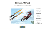
EXPERT Exercise and Dance Pole
INSTRUCTION MANUAL
READ THIS
IMPORTANT INFORMATION
Removable Exercise Poles
As with any removable, portable pole that uses pressure between the floor and ceiling to keep it stable, possible damage could
occur to the ceiling. The ‘XPERT’ pole is no different from any other pressure supported pole in this regard. The fact
that damage could occur must be fully understood and accepted before use. Vertical Leisure Ltd, X-Pole US Inc,
their distributors, sales persons or any other persons or associated companies can not be held responsible for any
damage to property or injury to persons or third parties during the use of this product.
If you do not accept that damage can occur:
- DO NOT Remove the XPERT Pole from its packaging
- DO NOT Assemble the XPERT Pole
- DO NOT Use the XPERT Pole
IMPORTANT: The XPERT Pole CANNOT be used with false, suspended or non-rigid ceilings.
If in any doubt contact your local X-Pole technical support team or visit the web site.
Most plasterboard or plaster ceilings, will flex/compress with pressure. This means that the retaining nails/pins/screws can be pushed
out of the plasterboard when pressure is applied by the pole adjuster. If this happens, just re-nail or re-tighten the fixing screws, fill and
re-paint. From then on the problem should not re-occur. If it does re-occur, re-enforcement may be needed in the area where the upper
dome is positioned. Information on this can be obtained on the X-Pole website or by contacting the X-Pole technical support team, or the
distributer in your country of purchase.
As damage can occur from the pressure used to keep the XPERT Pole in place, it is mandatory that the pole is centered under one or
two joists. The better aligned the upper support is under the centre of the joist and the more care taken in assembly and set up, the less
potential there is for damage.
If you do not accept that damage can occur – DO NOT assemble or use the XPERT Pole.
Please return the product in its fully packaged state, to your point of purchase for a refund.
A return can only be accepted at your point of purchase.
X-Pole make no apologies for explaining the above so our customers are absolutely
clear with regard to the potential problems that could occur.
DO NOT
Remove any of the parts from the carry case until you have read this
instruction manual from end to end and fully understood its contents.
Optional Ceiling Fixings
Box Contents
A-Pole
B-Pole
Extension 250mm (10”)
Top Adapter
Extension 125mm (5”)
X-Joint 200mm (8”)
X-Joint 200mm (8”)
X-Joint 180mm (7”)
Professional Exercise and Dance Pole
INSTRUCTION MANUAL
READ THIS
IMPORTANT INFORMATION
Removable Exercise Poles
As w ith any removable, p ortable pole that r elies on p ressure between t he
a nd c eiling to k eep i t stable, damage c an
occur to t he
o r ceiling. The X -Pole Spor’ i s no d ifferent f rom any other pressure s upported p ole in t his regard.
The f act t hat damage c an o ccur m ust be f ully u nderstood a nd accepted before u se. Vertical L eisure L td, X-Pole U SA,
its distributors, sales persons o r any other persons or associated companies can not be r esponsible f or a ny d amage to
property or injury to persons or third parties during the use of this product.
If you do not accept that damage can occur:
- DO NOT Remove X-Pole ‘Sport’ from its packaging
- DO NOT Assemble the X-Pole ‘Sport’
- DO NOT Use the X-Pole ‘Sport’
IMPORTANT: X-Sport CANNOT be used with false, suspended or non rigid ceilings.
If in doubt contact the X-Pole technical support team.
Most ceilings, whether plasterboard or lathe and plaster, will
with pressure. This means that the retaining nails/pins/screws can be
pushed out of the plasterboard when pressure is applied by the pole adjuster. If this happens, just re-nail or re-tighten the
screws,
and re-paint. From then on the problem should not re-occur. If it does re-occur, re-enforcement may be needed in the area where the
upper support is positioned. Information on this can be obtained on the X-Pole website or by contacting the X-Pole technical support
team, or the distributer in your country of purchase.
As d amage can occur from t he p ressure u sed to k eep the ‘Sport’ in p lace, the X-Pole ‘ Sport’ h as been designed with a wider
230mm (9”), upper s upport plate t o spread t he l oad and a id s tability. H owever, the better aligned the upper s upport is w ith a joint,
and the more care taken in assembly and set up, the less potential there is for damage.
Micro Base
If you do not accept that damage can occur – DO NOT assemble or Use the ‘Sport’ Pole. Please return the product in
its fully packaged state, to your point of purchase for a refund.
Only Return the X-Pole ‘Sport’ to your point of purchase. Do Not return it direct to Vertical Leisure Ltd, X-Pole USA.
Vertical Leisure make no apologies for explaining the above so our customers are absolutely
clear with regard to the potential problems that could occur.
Hex Key
Upper Dome
DO NOT
Remove any of the parts from the packing until you have read
and understood this instruction manual.
Instruction Manual
120mm - Vaulted Ceiling Mount
Designs Subject to Change
Carry & Storage Cases
Parts List
Part Description
XX045CR
XX045TG
XX045TM
XX050CR
XX050TG
XX050TM
(Chrome)
(T-Gold)
(T-Matt)
(Chrome)
(T-Gold)
(T-Matt)
Upper Dome
XP050CR-0010
XP050TG-0010
XP050CR-0010
XP050CR-0010
XP50TG-0010
XP050CR-0010
Vaulted Ceiling Mount **
XX050CR-0015
XX050TG-0015
XX050CR-0015
XX050CR-0015
XX050TG-0015
XX050CR-0015
Top Adapter (Complete)
XX045CR-0016
XX045TG-0016
XX045CR-0016
XX045CR-0016
XX045TG-0016
XX045CR-0016
Main Pole A (Pole only)
XX045CR-0040
XX045TG-0040
XX045TM-0040
XX050CR-0040
XX050TG-0040
XX050TM-0040
Main Pole B
XX045CR-0050
XX045TG-0050
XX045TM-0050
XX050CR-0050
XX050TG-0050
XX050TM-0050
Base Plate 120mm (4.75”) w/Shaft
XX045CR-0090
XX045TG-0090
XX045CR-0090
XX045CR-0090
XX045TG-0090
XX045CR-0090
Extension - 100mm (4”) **
XS045CR-0100
XS045TG-0100
XS045TM-0100
XS050CR-0100
XS050TG-0100
XS050TM-0100
Extension - 125mm (5”)
XS045CR-0125
XS045TG-0125
XS045TM-0125
XS050CR-0125
XS050TG-0125
XS050TM-0125
Extension - 150mm (6”) **
XS045CR-0150
XS045TG-0150
XS045TM-0150
XS050CR-0150
XS050TG-0150
XS050TM-0150
Extension - 175mm (7”) **
XS045CR-0175
XS045TG-0175
XS045TM-0175
XS050CR-0175
XS050TG-0175
XS050TM-0175
Extension - 200mm (8”) **
XS045CR-0200
XS045TG-0200
XS045TM-0200
XS050CR-0200
XS050TG-0200
XS050TM-0200
Extension - 250mm (10”)
XS045CR-0250
XS045TG-0250
XS045TM-0250
XS050CR-0250
XS050TG-0250
XS050TM-0250
Extension - 300mm (12”) **
XS045CR-0300
XS045TG-0300
XS045TM-0300
XS050CR-0300
XS050TG-0300
XS050TM-0300
Extension - 500mm (19.75”) **
XS045CR-0500
XS045TG-0500
XS045TM-0500
XS050CR-0500
XS050TG-0500
XS050TM-0500
Extension - 750mm (29.5”) **
XS045CR-0750
XS045TG-0750
XS045TM-0750
XS050CR-0750
XS050TG-0750
XS050TM-0750
Extension - 1000mm (39.25”) **
XS045CR-1000
XS045TG-1000
XS045TM-1000
XS050CR-1000
XS050TG-1000
XS050TM-1000
X-Joint - 180mm Long
XJ045-180
X-Joint - 200mm Long
XJ045-200
Expansion Screws (2pcs) **
XJ045-200-04
f
f
f
f
f
f
f
f
f
f
f
f
Adjuster Cover
XX045CR-0035
XX045TG-0035
XX045TM-0035
XX050CR-0035
XX050TG-0035
XX050TM-0035
XX Carry Case
XX-CS01
f
f
f
f
f
** Option or Additional Parts
2
XJ050-180
XJ050-200
XJ050-200-04
X-Pole ‘XPERT’ Instructions
Joists usually run at 90° degrees to the
floorboards and will normally span between
the two walls in a room closest to each
other. Joists can be located by tapping with
a knuckle or using an optional joist/stud
finder.
Thank you for buying an XPERT Pole. The team at X-Pole have spent
a significant amount of time researching, designing and developing
the XPERT Pole. We want the XPERT Pole to be the worlds leading
Exercise and Dance pole, if it’s not we want to understand why not!
At X-Pole we thrive on positive criticism and suggestions! So contact us
if you have any comments or suggestions on how to improve our product.
To get the best from your X-Pole XPERT – with SAFETY being the
utmost priority – it is extremely important that you READ this
instruction manual from beginning to end and most importantly,
understand it!
Stud Finder
(Stud finder not included - Available from most hardware stores)
Fig.2
Centre
Point
If you have ANY questions whatsoever – before you assemble, install
or use your XPERT Pole – call your local technical support (details
on back page) or see the X-Pole XPERT section on the website.
Measure
DO NOT INSTALL OR USE your ‘XPERT’ pole, if you have any doubt
about how to assemble/install it or how to use it.
Single Joist
IMPORTANT
Due to the X-Pole ‘XPERT’ being used in circumstances outside and
beyond the direct control of Vertical Leisure Ltd, X-Pole US Inc, its
distributors, sales persons or any other persons or associated
companies, these parties cannot be held responsible for any accident,
injury to the user or any third party, or damage to property. This does not
negate your normal consumer rights.
Follow the simple but explicit instructions in this manual to get the best
results from your X-Pole XPERT. Safety is a priority at all times.
If in ANY doubt ASK before you install or use your XPERT pole.
Finding a suitable exercise and dance area
To use a dance pole properly you need to be able to rotate around
the pole with your arms outstretched and NOT be able to hit or touch
anything whilst rotating. Find the area by rotating around an imaginary
pole with your arms outstretched (Fig.1). You can use a chair as an
imaginary pole or measure a circle with a diameter of approximately
3000 - 3500mm (120” - 138”). This are will enable you to fully extend
your arms.
Fig.1
Bottom Loading
To find a joist above your ceiling tap across the ceiling with your
knuckle until a solid sound is heard, this will be a joist. Keep
tapping across the ceiling and the sound will become more hollow
– the space between joists. Once you have located a joist take a
position measurement from the wall for future reference (Fig.2).
Write this measurement in this instruction manual. When you take
the measurement make sure it is at 90° degrees to the joists, not
along them! Important Note: When searching for the joists it is mandatory to use
step ladders and to have a second person holding the ladder.
SAFETY is critical at all times.
Optional Installation Parts
In addition to the free standing upper support dome X-Pole offers a range
of optional installation fittings. These allow permanent fitting or semi
removable fitting of your X-Pole. See the web site for details.
Now you have found a suitable exercise area and the joist, it is time
for assembly and installation.
X-Joint
1.5~1.75M
X-Poles incorporate a revolutionary new type of tube joint called the XJoint (Pat. Pending) (See Fig. 3). The X- joint is very quick and easy
to use and gives the X-Pole additional strength, rigidity and stability over
other joint systems.
Fig.3
UNDO
TIGHTEN
Dance moves can be performed by experienced dancers in a smaller
space than recommended but for beginners the above space is
mandatory. Once you have located the correct sized clear area you
can look for the ceiling joists above the area you have selected
Locating ceiling joists (Fig 2)
Unless you are erecting the XPERT pole against a solid ceiling you will
need to find a joist or pair of joists to install the Upper Dome against.
XPERT poles CANNOT be installed against false, suspended
or non-rigid ceilings. Most ceilings are plasterboard or a similar
material which is attached to “joists”. Joists are the pieces of wood that
run from wall to wall and support your floors and ceilings (Fig.2).
Important - Because the XPERT Pole uses pressure to stabilise itself,
it is essential that you centralise the upper support plate under
the centre of a ceiling joist (Fig.2). This is Mandatory.
X-Joint
(Arrow Mark)
180mm
Locking Pin
UNDO
UNDO
TIGHTEN
TIGHTEN
UNDO
TIGHTEN
200mm
However, to optimize the X-Joint key features and ensure
correct operation it is important that you follow these instructions.
Please read them fully before assembly.
There are two sizes of X-Joint 180mm and 200mm (Fig 3). The 180mm
joint has one half longer than the other. The short half of the 180mm
X-Joint, is marked with an arrow and it must always be installed with the
arrow pointing towards the ceiling, the end of the pole with the upper
dome.
The 180mm X-Joint is only used with the 125mm or less extensions.
However, it also may need to be used with some of the ‘optional’
gym fixing parts where a 200mm will not fit. The web site has details
of when 180mm X-Joint can be used.
3
Checking the Parts
Take your XPERT parts out of the box and lay them out on the floor.
Please check the contents of your XPERT pole with the contents
diagram on page 2. If anything is missing or damaged please call
your local X-Pole technical support immediately. The contact details are
on the back cover of this manual. We will be pleased to help.
Please study the contents and the part descriptions in the diagram, as
these are used throughout the instruction manual and are important for
installation. Also try the parts so you understand how they work. X-Pole XPERT Height Chart
Fig.4
125mm
250mm
If the ceiling is 2365mm (93.1”) you will see the range of the first pole
in the height calculator is 2235 - 2375mm (88” - 93.5”). This has no
extensions and is within your height requirement. However, the ceiling
height of 2365mm (93”) is very close to 2375mm (93.5”) the maximum
height shown in Fig. 4 and at this height you would be using nearly all
the 125mm (5”) of threaded adjuster. An extension is therefore needed
to reduce the amount of screw adjuster used.
If you now look at the next pole on the Fig. 4 chart you will see its
minimum height is 2360mm (93”) with 1x 125mm (5”) extension. So,
this means that with a 125mm (5”) extension your height of 2365mm
(93.1”) would use only a small amount of the adjuster.
So, by selecting the correct extension, it maximises the ‘useable pole’
and minimises the length of height adjuster needed.
Each size change has an overlap. Always go up a pole size
and use the next extension if possible.
125mm
Example
250mm
The XPERT can be used with ceilings up to 3050mm (120”) using the
standard upper support dome and optional extensions (purchased
separately). Additional extensions and other optional installation
parts can be purchased from your supplier or the X-Pole website.
For higher ceilings than 3050mm (120”) it is mandatory to use a fixed
ceiling plate or optional ceiling fixing. Further information is available
from your local technical support on the web site.
Extension Selection without the Height Chart
The basic height (no extensions) of the XPERT pole is 2235mm (88”)
with the adjuster closed. So if you subtract 2235 (88”) from the required
ceiling height the difference between the two will give you the overall
measurement used to select the required extension/s.
Example for ceiling with height of 2515mm:
Required Ceiling height - Closed Pole = Difference
Height 2515mm (99”) - 2235 (88”) = 280mm (11”)
Difference is 280mm (11”) so closest extension is 250mm (10”)
So, difference 280mm (10”) less extension 250mm (9.85”) = 30mm (1.2”).
Therefore using the 250mm extension means only 30mm (1”) of adjuster
expansion.
2235-2375mm
2360-2500mm
2485-2620mm
2610-2745mm
88”-93.5”
93”-98.5”
98”-103.25”
102.75”-108”
7’4”- 7’ 9½”
7’9”- 8’ 2½”
8’2”- 8’ 7¼”
8’6¾”- 9’
Size achievable from the box with 125mm & 250mm extensions
Extensions
A 125mm (5”) and 250mm (10”) extension are included in the set.
Optional extensions are available in 100, 125, 150, 175, 200, 250, 300,
500, 750 and 1000mm sizes. (4”, 5”, 6”, 7”, 8”, 10”, 12”, 19.5”, 29.5” &
39”).
Height Chart and Extension Selection
Using the full allowed length of the screw adjuster and both the
extensions included in the box the X-Pole XPERT will fit ceilings from
2235mm (88”) to 2735mm (108”). Any further increase in height will
require additional ‘Optional’ extensions which can be purchased from
your supplier or the X-Pole website.
The screw adjuster has the capability of extending the XPERT Pole by
125mm (5”). This is why a minimum and maximum height is shown on
the height chart (Fig.4) (i.e. between 2235 ~ 2375mm or 88” ~ 93.5”).
The Minimum height is with the pole screw adjuster closed - Maximum
height is with it fully extended 125mm (5”). You should NEVER use
more than 125mm (5”) of the adjuster.
Start by measuring the height of the ceiling at the centre point of use and
then refer to the height chart above (Fig. 4) which shows the pole tubes/
extensions to be used. Always match the ceiling height to the pole height
on the chart which uses the minimum adjuster length.
Minimising the number of extensions
Another key point is to minimise the number of extensions used for a
given height/extension requirement. So, if the required extension length is
500mm (20”) it is better to use 1x 500mm (20”) (optional) extension
than 2x 250mm (10”)
Calculation is the most accurate method of selection and allows for a
better extension selection. There is also a special height chart on
the web site. If you have any doubt about the extensions required or
how to select them please contact your local technical support, who
will be pleased to help.
Extension Installation
Correct installation of extensions and X-Joints is extremely important to
ensure strength and stability. Please read the next section paying
maximum attention to the correct procedure for installing X-Joints.
Fig.5
Height Adjuster/Cover
Top Adapter
Extension
Upper dome
B Pole
A Pole
Micro Base
Extensions should always be installed at the opposite end to the height
adjuster (Fig. 5). The smallest extension always goes closest to the upper
support plate. NEVER install extensions in the middle of the pole, this
is dangerous.
4
X-Joint Operation
The XPERT includes the very latest in pole joint technology the X-Joint.
This joint is simple, easy to use, very strong and stable. Just follow these
simple operational instructions to ensure the joint is properly locked. If in
ANY doubt contact the X-Pole technical support.
Fig.6
Hex Screw
Locking Pin
Hex Screw
UNDO
UNDO
TIGHTEN
TIGHTEN
X-Joint features a joining tube which expands and locks the pole tubes
together. The joint expansion is done by inserting a Hex Key, through holes
in the pole tubes and turning the key clockwise.
The markings on the tube show the direction to turn the hex key.
Clockwise to tighten and Counter-Clockwise to loosen/undo. It is very
important to remember this as when the tubes are in the pole the markings
are covered and cannot be seen.
There are two sizes of X-Joint. 180mm (7”) and 200mm (8”). The smaller
180mm (7”) is used with small extensions (125mm and below).
It can be identified by an arrow on the joint pointing towards the smaller
end (Fig.9). This end must be inserted pointing towards the smaller
extension. i.e. If you are using a 250 and 125mm the arrow end
ways points towards the 125mm extension and the top of the pole.
Fig.7
(Arrow Mark)
To undo the X-Joint - turn both hex screws ‘counter-clockwise’. Undo
screws until there is pressure against the key. Continue to apply slight
reverse pressure to the both screws to ensure the joint is fully released and
slides out.
Important Note: It is very important to make sure the Hex key is fully
inserted into the Hex expansion screws (Fig.10). Partial insertion can
damage the screw holes (rounding them) making it difficult to tighten
or more important undo the joint. (Spare expansion screws and fitting
instructions are available from the web site should they be damaged).
Fig.10
Main Tube
Inner
Hex
Screw
Hex Key
Partly inserted
Hex Key
Fully inserted
Tube Lock Pins
UNDO
X-joint
UNDO
TIGHTEN
125mm Extension
It is important to tighten progressively, alternating the screws, so that
the joint expands evenly, otherwise one side may not expand fully and the
pole tube joints may not lock fully tight.
TIGHTEN
180mm X-Joint
250mm Extension
At the center on either side of the joint is a pin. These pins slot into
corresponding U slots at the ends of the pole tubes (Fig.7). These
slots must go over the pins. The pins stop the pole tubes from rotating.
Fig.8
Main Pole
or
Extension
Before installation test the operation of the X-Joint on 2 tubes, it will help
with the assembly to be able to operate the X-Joints quickly and easily.
When asembling join the main poles with an X-Joint, then insert the next
X-Joint, add the next pole tube and tighten the X-Joint etc. Add extensions
and X-Joints as required to match ceiling height. It is better to firmly tighten
the X-Joints and then re-tighten them when the pole is installed as then the
weight/pressure of the pole tubes will push the joints tightly together.
Rounded Slot
Key Parts
With the height calculations done and extensions selected (if required), the
XPERT pole is ready for assembly.
X-Joint Installation
To install the X-Joint simply slide one half into a pole tube, ensuring
the 2x pins on the joint locate in the corresponding U slots in the
tube. When inserting the X-Joint make sure that the Hex locking
screws on the X-Joint align with the Hex Key holes in the pole
tube otherwise you will not be able to insert the Hex Key (Fig.10).
Fig.9
DO NOT ASSEMBLE YET - Continue to Read the Instructions first.
Key Parts of XPERT.
Fig.11
Locking Pin
Adjuster Locking Screws (x3)
Adjuster Flats
Adjuster Thread
Main Pole
or
Extension
Adjuster Cover
Hex Key Hole
X-Joint
Now attach the other tube, checking the hole alignment again and
then inserting the Hex Key into one of the key holes, turn lightly
‘clockwise’ until a slight pressure is felt. DO NOT fully tighten. Check
the tube edges are tight together and then lightly tighten the screw
in the other tube and then continue tightening alternating screws.
Tighten progressively until reasonably tight. DO NOT FORCE.
Static/Spinning Screws (x2)
Micro Base
Alignment ‘X’
5
Attaching the Base
The first part of the XPERT assembly is to attach the base to the A Pole.
Making sure the 2x Static/Spinning screws are fully undone, slide the
main A Pole onto the base shaft (Fig.12). Note the 2 flat sections on the
shaft (‘Flats’), these are where the hex screws will locate to stop the
pole from spinning. The flats sections are in line with the ‘X’ on the base.
Fig.12
A Pole
Flats (x2)
Base Shaft
Once the A Pole is on the shaft, align one of the Hex screws up with the
‘X’ on the base and tighten till pressure is felt. Then tighten the other one,
then visa a versa till tight. Once the base is attached stand the pole on the
base.
XPERT Adjuster Operation
During Installation the final height adjustment of the pole is done by the
A Pole ‘screw adjuster’ located under the adjuster cover. Unscrew the
adjuster cover ‘Clockwise’ i.e. with the tube in front of you rotate the
cover from right to left - undoing it. Unscrew until loose and the adjuster
thread is fully exposed. There is an O-ring so a little pressure may be
needed to help it slide down (Fig.13).
Hex Screws (x3)
Fig.13
Adjuster Thread
O-ring
A POLE
Upper Dome
Top Shaft
Static/Spinning Screws (x2)
Alignment ‘X’
Micro Base
Fig.14
B Pole or Extension
Be careful, as you lift to install the XPERT, that the Top Adapter Unit
does not fall out as it is lifted into position.
Installation
When assembled the XPERT pole is heavy and at full height it is not
easy to handle. It is unstable and difficult to lift into position. It is therefore
mandatory/compulsory that 2 people install the XPERT pole. i.e. 2
people should lift it into position and expand the height adjuster.
First make sure the base of the assembled XPERT Pole is at the centre
point of your dance area and under the selected joist.
With one person firmly holding the base in position, to stop it slipping, the
other person should slowly and very carefully lift the pole from the top end,
raising it (using hand over hand movements) until it is vertical and under
the joist position. Take care while holding the pole vertical in case it slips.
Once vertical, and with the second person still holding the base, unwind
the pole, counter-clockwise (i.e. rotate left to right), this will expand the
pole until it touches the ceiling.
Flats (x3)
Turn Clockwise to undo
Pole Rotation
Rotating the pole tube to the Right (Counter-clockwise) - as you look at
the vertical pole - Tightens/Expands the pole.
Adjuster Cover
The XPERT screw adjuster is locked and unlocked using the 3x Hex screws
on the main pole above the cover screw. Undo the 3 hex screws till they
are flush and the pole will spin on the adjuster shaft. Counter clockwise
rotation will undo the pole, making it longer and increasing the pressure.
Clockwise rotation will shorten/release it. Doing up the 3 Hex screws
against the 3 ‘Flat’ sections on the adjuster shaft will lock the adjuster. Test
this operation several times and make sure you are conversant with it.
Leave the 3 hex screws undone ready for installing the pole. The adjuster
cover can be put back in position to stop any grease being rubbed off.
When re-attaching the adjuster cover, take care not to cross thread the
screw. If it does not go on first time DO NOT force it. Undo and try again
gently.
Now you understand the operation of the XPERT you can assemble and
install it.
Rotating the pole tube to the Left (Clockwise)
the pole.
First lay the A pole down and start adding the pole tubes. Once familiar
with XPERT assembly it may be easier to add the base unit after pole tube
assembly but the first time assemble as advised.
Next insert a 200mm X-Joint into the A pole, make sure it is in its slot, add
the B pole tube and tighten the X-Joint hex screws as previously explained.
Then, as required, keep adding X-Joints and extensions as selected
to match the ceiling height. DO NOT forget. If you are using extensions
they are installed getting progressively smaller towards the ceiling and
with a 125mm or smaller extensions you only use the 180mm X-Joint
and make sure the ‘Arrow’ is pointing towards the ceiling.
Once the pole is assembled insert the Top Adapter unit into the last
extension and add the upper dome unit (Fig.14).
- Undoes/Shortens
Final Adjustment
Once the upper dome is against the ceiling and before it is tightened further make sure the pole is vertical. The best way to do this is with a builders
level/bubble or visually align the pole - with a door frame, window frame,
room corner etc. - from 2 sides at 90° to each other. Whilst aligning the
pole make sure the other person is still holding it in position in case it
should slip or fall.
Very Important: It is critical that the Upper Support Plate is flat against the
ceiling/joist. Please see Fig.15. DO NOT expand the adjuster further until
the upper plate is flat against the ceiling/joist.
If the Upper Plate in not flat the plate could rotate on one edge and slip or
damage the ceiling.
XPERT Installation
Top Shaft Attachment
Top Adapter
Upper Dome flat against the ceiling
Fig.15
Tip – As some floors and ceilings are very flexible it helps, once the pole is
tight, have someone to stand on the base and then re-tighten.
This compresses the floor and also makes it easier to rotate the adjuster.
If the pole is not vertical move the base plate in the required direction to
correct it. DO NOT move the Upper Dome which must be kept over the
centre of the joist at all times.
6
Once satisfied that the XPERT Pole is vertical and that the upper dome
is in the center of the joist and flat and against the ceiling, the adjuster
can be tightened/expanded. With the second person still holding the
XPERT Pole vertical slowly unwind the adjuster - turning the whole pole
counter-clockwise increasing the length/pressure.
The very ‘fine’ or ‘close’ thread on the X-Pole makes it very easy to adjust
and exert the pressure required to hold the pole in place. However,
this also means it is possible to exert ‘too much’ pressure if you are not
careful and damage the upper done and/or ceiling. It is therefore
important to adjust the XPERT adjuster pressure progressively.
Tighten until good positive pressure is felt and the pole is firmly in place.
Once satisfied that the pole is firmly in position, gripping the pole,
lean to one side applying sideways pressure to the pole. If the pole
feels tight and does not move try a practice swing with your feet on the
floor and your arm outstretched putting as much weight on the pole
as you can. Try this several times.
If the pole moves, re-check its alignment and tighten further until
it does not slip anymore. Next try swinging with your feet off the floor.
Re-tighten as necessary until there is no movement.
Adjuster Locking and Cover
Once the pole is tight align the three Hex screws with the 3 flat
sections on the adjuster shaft and tighten the screws firmly. It helps
to rock/rotate the pole very gently back and forth as you tighten
the first screw to help seat it. Then tighten the others without
rocking the pole. See web site for further info.
Fig.16
Flats (x3)
It is very important to remember that because XPERT pole uses
pressure to retain it in position it can un-tighten and/or become loose,
with use. The pole tightness should be checked regularly during use,
definitely every 25~30 minutes. If there is any movement DO NOT use.
Re-tighten and then re-test again before use. Also regularly check that
the X-Joints are tight.
Pole Removal
To take down your XPERT pole undo the adjuster Clockwise until free
from ceiling. Take care the pole does not fall over. Remove the upper
dome, remove the base plate, lay pole tubes on the floor, undo X-Joints,
remove pole tubes and extensions and pack away in the carry case. Store
only in a warm, dry place.
BEFORE USING YOUR POLE
Mis-using a pole can be dangerous not only to you but also anyone close
to the pole. The use of a dance pole is always at the user’s discretion.
Pole Exercise is extremely physical and uses muscles that you will
not have used before and therefore if you are not warmed up muscle
damage, strains and injury can occur. Before using the X-Pole XPERT
it is mandatory to warm up and, after use, warm down.
It is highly recommended that before you use your XPERT Pole you
purchase a suitable DVD to learn the basic moves. Never try moves
beyond your ability without an Instructor.
If at any time whilst using your pole you feel uncomfortable, your
muscles hurt, or you are short of breath – take a break and try again later.
Always rest between moves.
Have Fun with your X-Pole XPERT
Unlocked Hex Screw
Locked
Hex Screw
IMPORTANT - Pole Tightness
The X-Pole Team
TOP VIEW
Locked
Hex Screw
‘Counter-Clockwise
Turn’
A POLE
Setup Check List
Adjuster Cover
Unlocked
Hex Screw
Once the pole adjuster is locked, refit the adjuster cover. Take care, as
described before not to cross thread the cover. If it does not ‘bite’ at first,
try again. DO NOT force the screw action.
Your XPERT pole is now ready for use
Static and Spinning
To change the pole mode from static to spinning undo the 2x Hex screws
at the bottom of the pole until they are flush with the outer surface of
the pole. To return to static, align one of the Hex screws with the ‘X’
on the base plate and tighten. The screw must be aligned with
the X otherwise damage can be done to the shaft.
When tightening the Hex screws for static, use the same method as above
for the adjuster, rocking the pole slightly as the first screw is tightened.
Check floor to ceiling height
Refer to height chart for correct extension(s) (if needed)
Locate ceiling joist
Put base plate under joist centre position
Attach pole tubes/extension(s) (if needed) using X-Joints
Tighten X-Joints
Continue adding X-Joints/extensions/B Pole to fit height
Attach base plate
Attach Top shaft and upper dome.
Lift pole into position – base plate under joist centre
Rotate pole Counter-Clockwise (left > right) to expand
Check pole is vertical (use level/bubble or align with door/window)
Tighten until pole firmly in position
Lock adjuster with 3x Hex Screws
Refit adjuster cover
Check pole by rotational pressure with feet on floor
Check pole by performing spin
Re-tighten/align pole as necessary
DO NOT use pole if in doubt about its tightness or positional stability.
RE-CHECK tightness every 25~30 minutes or after heavy use.
Warranty
X-Pole XPERT and its associated parts are guaranteed free of manufacturing defect for a period of 6 months from date of purchase. Defects from use,
wear and tear, chipped edges from pole to pole contact or being dropped and anything outside of a pure manufacturing defect are not covered. This does
not affect your statutory rights. X-Pole, at its own discretion, will replace or re-fund damaged items. The user must return the item to the point of purchase
after which it will be returned to X-Pole for evaluation and appropriate action.
7
TROUBLE SHOOTING
Maintenance
Trouble Shooting
The plating can also be affected/damaged if the pole tubes are dropped.
Hex Keys/Screws – It is important to make sure the Hex key is fully
inserted into the hex expansion screw. Partial insertion can damage the
screw holes (rounding then during operation) making it difficult to tighten or
more importantly undo the joint. Spare screws are available from the web
site should they be damaged.
The X-Pole XPERT should require very little maintenance. Most important
is to check the edges of the pole tubes for damage because if damaged
or dented the chrome plating could come off. Chrome plating is very sharp
and could cut the skin so make sure the edges of the pole tubes are looked
after.
Always check the pole plating before use and check the joints and pole
tubes for any sharp edges. DO NOT use the XPERT Pole if the surface is
damaged in any way. Contact the local support office.
Cleaning – Your pole will need regular cleaning as you use it.
Clean your pole with a glass cleaner or similar non abrasive cleaner.
NEVER use water. Use a clean, smooth cloth to both clean and dry the
pole tubes. Do not clean with an oil or spray such as WD40 or similar.
X-Joint Screws – regularly check the X-Joint expansion screws to make
sure they operate smoothly. A light oil (Not WD40) should be applied to the
screw thread. Apply and adjust in and out a few times to spread the oil
down the threads.
Also check the Hex screw holes that the key goes into. These can become
rounded with constant use preventing the joint from retracting. If the holes
go round new screws can be bought from the X-Pole web site.
Hex Keys – The edges of the Hex keys can become rounded with use.
Do not used rounded keys as these can damage the screws. Replace the
key.
Base Screws – the 4 screws on the base can come loose with regular
use. Check and re-tighten regularly. Spare screws are available on the
website.
The X-Pole XPERT is the latest in pole technology and should not need
any support providing the regular maintenance is carried out and the pole
is looked after, cared for and stored properly.
Keep watching the X-Pole website for any product updates and the
release of new products and optional parts for the XPERT. Please feel free
to call our offices for help and advice on your XPERT Pole.
Warnings
Storage – it is extremely important not to keep your pole in a wet
or damp environment. DO NOT leave it in the back of the car or in an
outside shed etc, where it could become damp. Damp/Humid weather will
cause rust which could effect the plated surface and the tubes.
Always keep the pole in a warm dry environment.
Grip Chalk – Dancers use hand chalk to improve grip and in cases of
sweaty hands. Never use ‘climbing’ chalk or powder chalk on a dance pole.
Only ever use special liquid grip chalk such as X-Grip, Mighty Grip, Gorilla
Grip or other specialist pole chalk. Powder chalks can damage the pole
surface and clog up the joints and other mechanisms.
Height measurement – It is essential to measure the height of your
ceiling and select the correct extensions to suit. Mistakes are often made
in measuring heights especially with inches where 96” becomes 9’6” and
116” is 11’ 6’. These are factual cases where wrong measurements have
been made and the wrong parts purchased or used.
Safety Warning
Should you have any concerns regarding your XPERT pole, its suitability for use, its correct installation, your ability to use the pole or any
other possible factor relating to the installation or use this product please call X-Pole technical support before use. Use of this pole is entirely
at owners and/or users descretion.
Vertical Leisure Ltd
45 - 47 High Street
Potters Bar. Herts.
EN6 5AW. UK
Vertical Leisure Ltd - UK
E-mail: [email protected]
www.x-pole.co.uk
Tel: +44 (0)1707 665933
X-Pole US Inc - USA
E-mail: [email protected]
Web: www.xpoleus.com
Tel: +1 (818) 255 1880
© Copyright 2009 - Vertical Leisure Ltd / XPole US Inc
Dance4Me - Australia
E-mail: [email protected]
Web: www.xpole.com.au
Tel: +61 (0)2 9371 3776
1/10/2009