1
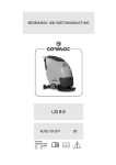
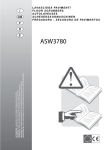
Y
91
91
96 97
FIG.29D
(I)
Rimontare come in origine il cruscotto ed i componenti smontati
in precedenza, posizionare il guidaluce dell’impianto elettrico
comandi "91" come visibile in figura nella zona centrale del cruscotto. Inserire il guidaluce dell’impianto elettrico comandi "91"
attraverso il foro "Y" praticato in precedenza nel tunnel centrale.
Inserire ad incastro l’interruttore "97" con relativa cornice "96" in
corrispondenza del foro "Y" ed eseguire il collegamento elettrico
all’impianto elettrico "91" (vedi pos.1 dello schema elettrico allegato).
(F)
Reposer, comme à l'origine le tableau de bord et les composants précédemment déposés. Positionner le guide-lumière du faisceau
électrique des commandes "91", à travers le trou "Y", précédemment effectué sur le tunnel central. Emboîter l'interrupteur "97" avec son
cadre "96" dans le trou " Y " et effectuer la connexion électrique au faisceau électrique "91" (voir pos. 1 du schéma électrique joint).
(GB)
Return all components that were removed from the dashboard to their original positions, and set the supplied wiring system guide light
"91" in the central portion of the dashboard as indicated in the figure. Insert the supplied wiring system "91" guide light through hole "Y"
prepared in the central console. Snap switch "97" and its frame "96" into hole "Y" and hook up the supplied wiring system "91" (see the
enclosed wiring diagram, pos. 1).
(D)
Wie im Original das Armaturenbrett und die vorher ausgebauten Bauteile wieder einbauen und die Lichtanlage der Bedienung "91" wie
in der Abbildung sichtbar in der Mitte des Armaturenbretts positionieren. Die Lichtanlage der Bedienungsanlage "91" durch die vorher in
der Mittelkonsole durchgeführten Bohrung "Y" einführen. Schalter "97" mit entsprechendem Rahmen "96" in Bohrung "Y" festklemmen
und die elektrischen Anschlüsse "91" ausführen (siehe Pos 1 des Schaltschemas im Anhang).
(E)
Volver a montar como en origen el tablero y los componentes desmontados anteriormente, colocar la guía de luz de la instalación eléctrica mandos "91" como visible en figura en la parte central del tablero. Inserir la guía de luz de la instalación eléctrica mandos "91" a
través el orificio "Y" efectuado anteriormente en el túnel central. Inserir a encastre el interruptor "97" con correspondiente marco "96" en
correspondencia con el orificio "Y" y efectuar la conexión eléctrica a la instalación eléctrica "91" (véase pos.1 del esquema eléctrico adjunto).
38