1
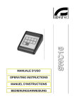
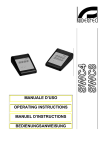
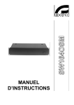
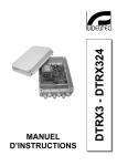
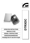
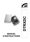
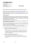
'&5(7;8
MANUALE D’USO
__________________________
OPERATING INSTRUCTIONS
__________________________
MANUEL D’INSTRUCTIONS
__________________________
BEDIENUNGSANWEISUNG
'&5(7;8
MANUALE
D’USO
INDICE
INDICE ....................................................................................................................................................................................1
INTRODUZIONE .....................................................................................................................................................................2
Contenuto dell’imballo ............................................................................................................................................................................... 2
Cosa contiene questo manuale ................................................................................................................................................................. 2
Convenzioni tipografiche ........................................................................................................................................................................... 2
NORME DI SICUREZZA.........................................................................................................................................................2
DATI DI MARCATURA ...........................................................................................................................................................3
DESCRIZIONE DEL DISTRIBUTORE DI DATI SERIALI DCRE485 .....................................................................................3
Caratteristiche ........................................................................................................................................................................................... 3
Apparecchi compatibili per l’uso con il distributore di dati digitali DCRE485............................................................................................. 3
Esempio di installazione ............................................................................................................................................................................ 4
Cavi............................................................................................................................................................................................................ 4
INSTALLAZIONE ....................................................................................................................................................................5
Apertura dell’imballaggio ........................................................................................................................................................................... 5
Controllo della marcatura .......................................................................................................................................................................... 5
CONNETTORI E COLLEGAMENTI .......................................................................................................................................5
ACCENSIONE E SPEGNIMENTO..........................................................................................................................................7
MANUTENZIONE....................................................................................................................................................................7
RISOLUZIONE DI PROBLEMI ...............................................................................................................................................7
CARATTERISTICHE TECNICHE ...........................................................................................................................................7
Il produttore declina ogni responsabilità per eventuali danni derivanti da un uso improprio delle
apparecchiature menzionate in questo manuale; si riserva inoltre il diritto di modificarne il contenuto
senza preavviso.
Ogni cura é stata posta nella raccolta e nella verifica della documentazione contenuta in questo
manuale: tuttavia il produttore non può assumersi alcuna responsabilità derivante dall’utilizzo della
stessa. Lo stesso dicasi per ogni persona o società coinvolta nella creazione e nella produzione di
questo manuale.
Pag. 1
DCRE485 0600
Introduzione
Contenuto dell’imballo
• 1 distributore di dati seriali DCRE485
• 8 cavi telefonici6/6 dritto dritto - lunghezza ca.150 cm
• 8 scatole di derivazione RJ jack
• 1 manuale d’uso
Alla consegna del prodotto verificare che l’imballo sia integro e non abbia segni evidenti di cadute o abrasioni. In caso
di evidenti segni di danno all’imballo contattare immediatamente il fornitore.
Controllare che il contenuto sia rispondente alla lista del materiale sopra indicata.
Cosa contiene questo manuale
In questo manuale è descritto il distributore di dati seriali DCRE485 , con le particolari procedure di installazione,
configurazione e utilizzo. E’ necessario leggere attentamente questo manuale, in particolar modo il capitolo
concernente le norme di sicurezza, prima di installare ed utilizzare il distributore di dati seriali.
Convenzioni tipografiche
Nel presente manuale si fa uso di diversi simboli grafici, il cui significato è riassunto di seguito:
Rischio di scariche elettriche; togliere l’alimentazione prima di procedere con le operazioni, se non é
espressamente indicato il contrario.
L’operazione é molto importante per il corretto funzionamento del sistema: si prega di leggere attentamente la
procedura indicata, ed eseguirla secondo le modalità previste.
Descrizione delle caratteristiche del sistema: si consiglia di leggere attentamente per comprendere le fasi
successive.
Norme di sicurezza
Il distributore di dati seriali DCRE485 é conforme alle normative vigenti all’atto della pubblicazione del
presente manuale per quanto concerne la sicurezza elettrica, la compatibilità elettromagnetica ed i requisiti generali.
Si desidera tuttavia garantire gli utilizzatori (tecnico installatore e operatore) specificando alcune avvertenze per
operare nella massima sicurezza:
• Collegare ad una linea di alimentazione corrispondente a quella indicata sulle etichette di marcatura (vedere il
successivo capitolo Dati di marcatura)
• La presa di alimentazione deve essere connessa a terra secondo le norme vigenti
• Prima di spostare o effettuare interventi tecnici sull’apparecchio, disinserire la spina di alimentazione
• Non utilizzare cavi di tensione con segni di usura o invecchiamento, in quanto rappresentano un grave pericolo per
l’incolumità degli utilizzatori
• L’installazione dell’apparecchio (e dell’intero impianto di cui esso fa parte) deve essere effettuata da personale
tecnico adeguatamente qualificato
• L’apparecchio deve essere aperto soltanto da personale tecnico qualificato. La manomissione dell’apparecchio fa
decadere i termini di garanzia
• Non utilizzare l’apparecchio in presenza di sostanze infiammabili
• Non permettere l’uso dell’apparecchio a bambini o incapaci
• Accertarsi che l’apparecchio sia fissato in maniera solida e affidabile
• L’apparecchio si considera disattivato soltanto quando l’alimentazione é disinserita e i cavi di collegamento con altri
dispositivi sono stati rimossi
• Per l’assistenza tecnica rivolgersi esclusivamente al personale tecnico autorizzato
• Conservare con cura il presente manuale per ogni futura consultazione
Pag. 2
DCRE485 0600
Dati di marcatura
Sul distributore di dati seriali DCRE485 sono riportate due etichette conformi alla marcatura CE.
La prima etichetta contiene:
• Codice di identificazione del modello (Codice a barre Extended 3/9 )
• Tensione di alimentazione (Volt)
• Frequenza (Hertz)
• Consumo (Watt)
La seconda etichetta indica il numero di serie del modello (codice a barre Extended 3/9)
All’atto dell’installazione controllare se le caratteristiche di alimentazione del distributore di dati seriali corrispondono
a quelle richieste. L’uso di apparecchi non idonei può portare a gravi pericoli per la sicurezza del personale e
dell’impianto.
Descrizione del distributore di dati seriali DCRE485
L’unità DCRE485 è un distributore di dati seriali gestito a microprocessore. Esso permette il controllo delle
unità di telemetria DTRX1, DTMRX1, MICRODEC485 in configurazione a stella. Restituisce i dati in ingresso
contemporaneamente sulle 8 linee di uscita RS485.
Caratteristiche
• 1 Ingresso seriale in modalità RS485
• 8 uscite seriali in RS485 per la restituzione dei dati ricevuti dall’ ingresso
• Possibilità di collegamento in cascata con altre unità DCRE485
Apparecchi compatibili per l’uso con il distributore di dati digitali DCRE485
• DCS3: tastiera di controllo.
• Ricevitore di comandi DTRX1: ricevitore digitale a 17 funzioni, consente il controllo a distanza di un brandeggio
motorizzato, di lavavetri e pompa, e di 4 contatti ausiliari. È indirizzabile singolarmente fino a 99 unità. Se dotato di
scheda opzionale permette la gestione di max 14 posizioni di preset, richiamabili in ciclata con la funzione patrol.
• Miniricevitore di comandi DTMRX1: ricevitore digitale a 11 funzioni, consente il controllo di base di un brandeggio
motorizzato (orizzontale e verticale, ottiche, autopan). Indirizzabile singolarmente fino a 64 unità.
• Miniricevitore di comandi MICRODEC485: consente il controllo remoto di un brandeggio e di un’ottica
motorizzata. E’ possibile indirizzare fino a 32 ricevitori.
Pag. 3
DCRE485 0600
Esempio di installazione
Un operatore con più monitor, con controllo di una serie di brandeggi in configurazione mista (a stella e in cascata)
MATERIALE
DTMRX1
DTMRX1
DTMRX1
DCRE485
DTMRX1
SW328
Parte di controllo:
1 tastiera di controllo DCS3
Parte video:
1 commutatore video SW328
2 monitor
4 telecamere
Parte telemetria:
1 distributore di dati DCRE485
4 ricevitori DTMRX1
4 brandeggi
DCS3
Cavi
Nello schema d’esempio sono stati utilizzati di versi tipi di tratto per indicare cavi di diversa funzione:
cavo video:
coassiale RG 59 o cavo equivalente.
cavo multipolare:
ogni funzione di controllo del brandeggio viene attivata / disattivata da un relè interno al ricevitore.
Stabilire il numero finale di cavi, seguendo le indicazioni seguenti:
7 fili per la movimentazione del brandeggio: destra, sinistra, alto, basso, autopan, comune, terra
6 fili di controllo per ottiche ad inversione di polarità (zoom, focus, iris)
4 fili di controllo per ottiche a filo comune (zoom, focus, iris)
2 fili per l’ ausiliare
Nota: è consigliato l’utilizzo di differenti cavi multipolari per le funzioni in bassa tensione ed in alta tensione.
Sezione minima consigliata:
0,56 mm.² (AWG 20) per fili in alta tensione (brandeggio)
0,34 mm.² (AWG 22) per fili in bassa tensione (ottica, ausiliare)
cavo per la ricezione/trasmissione digitale dei comandi:
2 fili per la ricezione dall’unità di comando (doppino telefonico twistato, sezione 0,22 mm.² AWG 24)
2 fili per la eventuale trasmissione al ricevitore successivo nelle configurazione in cascata (doppino telefonico
twistato, sezione 0,22 mm.² AWG 24)
Nota: la distanza massima del collegamento é di circa 15 m in RS232; 1500 m in Current Loop.
Pag. 4
DCRE485 0600
Installazione
La fase di installazione deve essere effettuata solo da personale tecnico qualificato.
Le seguenti procedure sono da effettuare in assenza di alimentazione, se non diversamente indicato.
Apertura dell’imballaggio
Se l’imballo non presenta evidenti difetti (dovuti a cadute o abrasioni anomale), procedere al controllo del materiale in
esso contenuto, secondo la lista fornita al paragrafo Contenuto dell’imballo al capitolo Introduzione.
I materiali d’imballo sono costituiti interamente da materiale riciclabile. Sarà cura del tecnico installatore smaltirli
secondo le modalità di raccolta differenziata o comunque secondo le norme vigenti nel Paese di utilizzo.
Controllo della marcatura
Prima di procedere con l’installazione controllare se il materiale fornito corrisponde alle specifiche richieste,
esaminando le etichette di marcatura, secondo quanto descritto al capitolo Descrizione della marcatura.
Non effettuare per nessun motivo alterazioni o collegamenti non previsti in questo manuale: l’uso di apparecchi non
idonei può portare a gravi pericoli per la sicurezza del personale e dell’impianto.
Connettori e collegamenti
L’unità DCRE485 presenta 9 connettori RJ11 posti sul retro della meccanica ed un fusibile di protezione.
Tutte le linee RS485, sia in ingresso che in uscita, presentano la resistenza di terminazione inserita.
La trasmissione dei dati digitali dalle uscite è effettuata contemporaneamente in RS485 sulle 8 uscite.
Alimentazione
Uscite seriali RS485
Ingresso seriale RS485
Fusibile 63mAT 250V
Pag. 5
DCRE485 0600
Per il collegamento con il cavo twistato, collegare gli apparecchi tramite le scatole di derivazione RJ, fornite dal
fabbricante, secondo le tabelle di riferimento riportate di seguito:
Collegamento tastiera DCS3 - distributore DCRE485
DCRE485
Collegamento RS485: distanza max 1200 m
DCS3
DCRE485
RS485A Bianco ------------- Blu
RS485A
RS485B Giallo -------------- Nero RS485B
DCS3
Collegamento distributore DCRE485 – Ricevitore
DTMRX1
Collegamento RS485: max 1200 m
DCRE485
Ricevitore
RS485A
Bianco ------------------------- Rx485A
RS485B
Giallo -------------------------- Rx485B
M a x 12 00
R S 485
DCRE485
Per il collegamento alla morsettiera dei ricevitori fare riferimento ai rispettivi manuali d’uso.
Pag. 6
DCRE485 0600
Accensione e spegnimento
Prima di fornire alimentazione:
• controllare se il materiale fornito corrisponde alle specifiche richieste, esaminando le etichette di marcatura,
secondo quanto descritto al capitolo Descrizione della marcatura.
• controllare che il fusibile di protezione del distributore DCRE485 sia integro
• controllare che il distributore DCRE485 e gli altri componenti dell’impianto siano chiusi e sia quindi impossibile il
contatto diretto con parti in tensione.
• accertarsi che tutte le parti siano fissate in maniera solida ed affidabile
• controllare che le fonti di alimentazione ed i cavi di collegamento siano in grado di sopportare il consumo del
sistema
Manutenzione
Il distributore di dati seriali DCRE485 non necessita di particolare manutenzione.
Si raccomanda di utilizzarlo poggiato su una base solida, con i cavi di alimentazione e di collegamento in posizione tale
da non essere causa di intralcio all’operatore.
Risoluzione di problemi
Il distributore di dati seriali DCRE485 è caratterizzato da una notevole facilità d’uso, ma ciononostante possono
insorgere dei problemi sia in fase di installazione, di configurazione o durante l’uso.
Problema
All’accensione la spia luminosa
non si accende
Dopo l’accensione la tastiera
DCS3 collegata non funziona
I ricevitori non rispondono ai
comandi
Possibile causa
Manca alimentazione
Intervento correttivo
Controllare il cavo di alimentazione
Fusibile bruciato
Lampadina bruciata
Configurazione errata della modalità
di trasmissione
Collegamento non corretto
Il cavo telefonico è collegato sul
connettore sbagliato della tastiera
DCS3
Collegamento non corretto
Sostituire il fusibile
Sostituire la lampadina
Controllare il settaggio della tastiera
DCS3
Controllare i cavi di collegamento
Controllare che il cavo telefonico sia
inserito nel connettore corretto
Il numero di identificazione del
ricevitore non è corretto
Il cavo telefonico è collegato sul
connettore sbagliato della tastiera
DCS3
Controllare i cavi di collegamento
Controllare il numero di identificazione del
ricevitore (fare riferimento ai manuali
d’uso)
Controllare che il cavo telefonico sia
inserito nel connettore corretto
Caratteristiche tecniche
Tensione:
Potenza:
Fusibile di protezione:
Temperatura di funzionamento:
Dimensioni:
Peso:
230 V~, 50 Hz (riferirsi ai dati di marcatura)
10 W
63 mA T 230V
da 0°C a 40°C
180 x 160 x 50 mm
1,2 kg
Pag. 7
DCRE485 0600
'&5(7;8
OPERATING
INSTRUCTIONS
INDEX
INDEX......................................................................................................................................................................................1
INTRODUCTION.....................................................................................................................................................................2
Packing contents ....................................................................................................................................................................................... 2
Contents of this Manual ............................................................................................................................................................................. 2
Typographic conventions........................................................................................................................................................................... 2
SAFETY RULES .....................................................................................................................................................................2
IDENTIFICATION DATA.........................................................................................................................................................3
DESCRIPTION OF THE SERIAL DATA DISTRIBUTOR DCRE485......................................................................................3
Features .................................................................................................................................................................................................... 3
Appliances compatible for use with the digital data distributor DCRE485 ................................................................................................. 3
Installation example ................................................................................................................................................................................... 4
Cables ....................................................................................................................................................................................................... 4
INSTALLATION ......................................................................................................................................................................5
Unpacking.................................................................................................................................................................................................. 5
Check of identification data ....................................................................................................................................................................... 5
CONNECTORS AND CONNECTIONS ..................................................................................................................................5
SWITCHING ON AND OFF ....................................................................................................................................................7
MAINTENANCE ......................................................................................................................................................................7
PROBLEM SOLUTION...........................................................................................................................................................7
SPECIFICATIONS ..................................................................................................................................................................7
The manufacturer declines all responsibility for any damage caused by an improper use of the
appliances mentioned in this manual; furthermore, the manufacturer reserves the right to modify its
contents without any prior notice.
The documentation contained in this manual has been collected with great care: the manufacturer,
however, cannot take any liability for its use. The same thing can be said for any person or company
involved in the creation and production of this manual.
Pag. 1
DCRE485 0600
Introduction
Packing contents
• 1 serial data distributor DCRE485
• 8 phone cables 6/6 straight straight – Length about 150 cm
• 8 RJ jack-connection boxes
• 1 instruction manual
After the delivery, check that the packing is not damaged and shows no evident signs of falls or abrasion. Should this
be so, contact immediately the supplier.
Check that the contents correspond to the above-mentioned list of materials.
Contents of this Manual
This manual describes the serial data distributor DCRE485 together with its specific procedures of installation,
configuration and use. Read this manual carefully, in particular the chapter concerning the safety rules, before
installing and using the serial data distributor.
Typographic conventions
Different graphic symbols are used in this manual, the meaning of which is here described:
Hazard of electric shock; disconnect the power supply before proceeding, if not otherwise specified.
The operation is very important for the correct working of the system: read carefully the procedure indicated,
and carry it out according to the required modalities.
Description of system features: read carefully to understand the following phases.
Safety rules
The serial data distributor DCRE485 complies with the normative laws in force at the time of editing of this
manual, concerning electric safety, electromagnetic compatibility and general requirements.
Anyway, in order to ensure the users (installer technician and operator), the following warnings are specified for
safety’s sake:
• Connect to a feeder corresponding to the specifications indicated on the data plate (see next chapter Identification
data)
• The outlet must be correctly earthed according to the normative laws in force
• Before any shifting or technical operations on the appliance, unplug it from the mains
• Do not use voltage cables showing wear or ageing, since they may seriously compromise the users’ safety
• The appliance (and the complete system, which it belongs to) must be installed only by qualified technical staff
• The appliance must be opened only by qualified technical staff. The tampering of the appliance may void the
guarantee terms.
• Do not use the appliance in the presence of inflammable substances
• Do not allow children or people not familiar with the appliance to use it
• Make sure the appliance is fixed in a solid and reliable way
• The appliance is completely off-line only when the plug is diconnected and the cables connected to other appliances
have been removed
• For after-sale service call only authorized technical staff.
• Keep this manual close to hand for any future reference
Pag. 2
DCRE485 0600
Identification data
On the serial data distributor DCRE485 there are two plates complying with EC specifications.
The first plate includes:
• Model identification code (Extended bar code 3/9 )
• Mains voltage (Volt)
• Frequency (Hertz)
• Power consumption (Watt)
The second plate shows the model serial number (Extended bar code 3/9)
When installing the appliance, check that the power supply specifications of the serial data distributor correspond to
those required. The use of improper appliances may seriously compromise the safety of the personnel and the
installation.
Description of the serial data distributor DCRE485
The DCRE485 is a serial data distributor in RS485. It allows to control the DTRX1, DTMRX1, MICRODEC485
telemetry units in star configuration. It sends simultaneously the input data back to the 8 RS485 output lines.
Features
• 1 serial input in RS485 mode
• 8 RS485 serial outputs for the data sending back from the input
• Possibility of cascade connection to other units DCRE485
Appliances compatible for use with the digital data distributor DCRE485
• DCS3: keyboard.
• Receiver driver DTRX1: 17-function digital receiver, allowing the remote control of pan & tilt motors, wiper and
wash, and 4 auxiliary contacts. It can be individually addressed up to 99 units. If provided with the optional card
DTRP, it allows the management of max. 14 preset positions, which are recalled in the switching cycle by the patrol
function.
• Mini receiver driver DTMRX1: 11-function digital receiver, allowing the control of pan & tilt motors (horizontal and
vertical, zoom lenses, autopan). It can be individually addressed up to 64 units.
• Mini receiver driver MICRODEC485 : it allows the remote control of a Pan & Tilt motor and a zoom lens. Up to 32
receivers can be addressed.
Pag. 3
DCRE485 0600
Installation example
One operator with more than one monitor, controlling a series of pan & tilt motors in a mixed configuration (star and
cascade)
MATERIAL
DTMRX1
DTMRX1
DTMRX1
DCRE485
DTMRX1
SW328
Control part:
1 keyboard DCS3
Video part:
1 video switcher SW328
2 monitors
4 cameras
Telemetry part:
1 data distributor DCRE485
4 receivers DTMRX1
4 pan & tilt motors
DCS3
Cables
In the above scheme, different lines have been used to show different types of functions:
video cable:
coaxial RG 59 or equivalent cable.
multipolar cable:
each pan & tilt function is enabled / desabled by a relay inside the receiver.
Define the cable final number, following these indications:
7 wires for pan & tilt movement: right, left, high, low, autopan, common, ground
6 control wires for reverse polarity zoom lenses (zoom, focus, iris)
4 control wires for common ground zoom lenses (zoom, focus, iris)
2 wires for the auxiliary
Note: it is advisable to use different multipolar cables for low tension and high tension functions.
Minimum section advised:
0,56 mm.² (AWG 20) for high tension wires (pan & tilt)
0,34 mm.² (AWG 22) for low tension wires (zoom lens, auxiliary)
cable for control digital reception/transmission:
2 wires for the control unit reception (twisted pair cable, section 0,22 mm.² AWG 24)
2 wires for possible transmission to the following receiver in cascade configurations (twisted pair cable, section 0,22
mm.² AWG 24)
Note: the maximum connection distance is about 15 m in RS232; 1500 m in Current Loop.
Pag. 4
DCRE485 0600
Installation
The installation must be carried out only by qualified technical staff.
The following procedures must be carried out with power supply off, if not otherwise specified.
Unpacking
If the packing shows no relevant defects (due to falls or anomalous abrasions), check the material contained,
according to the list given at paragraph Packing contents chapter Introduction.
The packing materials can be completely recycled. The installer technician is required to dispose of them according to
the differentiated collecting modalities or ,anyway, according to the normative laws in force in the Country of use.
Check of identification data
Before installing the appliance, check that the material supplied corresponds to the specifications indicated on
the data plate, following the chapter Identification data. Do not carry out any modification or connections which are not
provided for in this manual: the use of improper appliances may seriously compromise the safety of the personnel and
the installation.
Connectors and connections
The DCRE485 unit features 9 RJ11 connectors located at the rear of the mechanics and one protection fuse:
Each line in RS485, both in input and in output, have the termination resistance inserted.
The transmission of digital data from the outputs takes place simultaneously in RS485 on the 8 outputs.
Power supply
Serial outputs RS485
Serial input RS485
Fuse 63 mAT 250V
Pag. 5
DCRE485 0600
For the connection by twisted cable, connect the appliances by means of RJ connector blocks, supplied by the
manufacturer, following these reference tables:
Connection of DCS3 keyboard - DCRE485 distributor
DCRE485
RS485 connection: max distance 1200 m
DCS3
DCRE485
RS485A
White ------------- Blue
RS485A
RS485B
Yellow ------------ Black
RS485B
DCS3
Connection of DCRE485 distributor - receiver
DTMRX1
RS485 connection: max 1200 m
DCRE485
Receivers
RS485A
White------------------------Rx485A
RS485B
Yellow ----------------------Rx485B
M a x 12 00
R S 485
DCRE485
For the receivers connection to the terminal board refer to the relevant user manuals.
Pag. 6
DCRE485 0600
Switching on and off
Before connecting the appliance:
• check that the material supplied corresponds to the specifications indicated on the data plate, following the chapter
Identification data
• check if the protection fuse of the DCRE485 distributor is in a good condition
• check that the DCRE485 distributor and the other components of the installation are closed in order to avoid direct
contact with energized parts.
• make sure that all the parts are fixed in a solid and reliable way
• check that the electrical capacity and the connection cables will support the system power consumption
Maintenance
The serial data distributor DCRE485 does not need a special maintenance.
Make sure it always rests on a solid base, and that the power supply and connection cables do not hinder the operator.
Problem solution
Even if the serial data distributor DCRE485 is very easy to use, some problems may arise during installation,
configuration or use.
Problem
At the switching on the pilot light
does not turn on
After the switching on, the
connected keyboard DCS3 do
not run
The receivers do not respond to
the controls
Possible cause
Power supply not connected
Remedy
Check the power supply cable
The fuse is blown
The lamp is blown
Improper configuration of the
transmission mode
Replace the fuse
Replace the lamp
Check the setting of DCS3 keyboard
Incorrect connection
The telephone cable is connected
to the wrong connector of the
DCS3 keyboard
Incorrect connection
Check the connection cables
Check that the telephone cable is cut in the
right connector
The receiver identification number
is wrong
The telephone cable is connected
to the wrong connector of the
DCS3 keyboard
Check the receiver identification number
(refer to user manuals)
Check that the telephone cable is cut in the
right connector
Check the connection cables
Specifications
Power supply :
Power consumption :
Protection fuse:
Operative temperature:
Dimensions:
Weight:
230 V~, 50 Hz (refer to identification data)
10 W
63 mA T 230V
from 0°C to 40°C
180 x 160 x 50 mm
1,2 kg
Pag. 7
DCRE485 0600
'&5(7;8
MANUEL
D’INSTRUCTIONS
INDEX
INDEX......................................................................................................................................................................................1
INTRODUCTION.....................................................................................................................................................................2
Contenu de l’emballage............................................................................................................................................................................. 2
Contenu de ce manuel .............................................................................................................................................................................. 2
Conventions typographiques ..................................................................................................................................................................... 2
NORMES DE SÉCURITÉ .......................................................................................................................................................2
CARACTÉRISTIQUES TECHNIQUES ...................................................................................................................................3
DESCRIPTION DU DISTRIBUTEUR DE DONNÉES SÉRIELLES DCRE485.......................................................................3
Caractéristiques......................................................................................................................................................................................... 3
Appareils compatibles pour l’emploi avec le distributeur de données numériques DCRE485 ......................................... ......................... 3
Exemple d’installation ................................................................................................................................................................................ 4
Câblage ..................................................................................................................................................................................................... 4
INSTALLATION ......................................................................................................................................................................5
Déballage .................................................................................................................................................................................................. 5
Contrôle des caractéristiques techniques.................................................................................................................................................. 5
CONNECTEURS ET RACCORDEMENTS.............................................................................................................................5
ALLUMAGE ET COUPURE....................................................................................................................................................7
ENTRETIEN ............................................................................................................................................................................7
RÉSOLUTION DES PROBLÈMES.........................................................................................................................................7
DONNÉES TECHNIQUES ......................................................................................................................................................7
Le producteur décline toute responsabilité pour les dommages éventuels dus à une utilisation non
appropriée des appareils mentionnés dans ce manuel; on réserve en outre le droit d’en modifier le
contenu sans préavis. La documentation contenue dans ce manuel a été rassemblée et vérifiée avec
le plus grand soin: cependant, le producteur ne peut pas s’assumer aucune responsabilité dérivante
de l’emploi de celle-là. La même chose vaut pour chaque personne ou société impliquées dans la
création et la production de ce manuel.
Pag. 1
DCRE485 0600
Introduction
Contenu de l’emballage
• 1 distributeur de données sérielles DCRE485
• 8 câbles téléphoniques 6/6 droit droit –Longueur 150cm à peut près
• 8 boîtes de dérivation RJ jack
• 1 manuel d’emploi
Lors de la livraison du produit, vérifier si l’emballage est intègre et s’il n’a pas subi de signes évidents de chutes ou de
choc. Si l’emballage présente des signes évidents de dommage, contacter immédiatement le transporteur. Vérifier que
le contenu correspond à la liste du matériel indiqué ci-dessus.
Contenu de ce manuel
Dans ce manuel on décrit le distributeur de données sérielles DCRE485, et les procédures particulières d’installation,
configuration et emploi. Il est nécessaire de lire attentivement ce manuel, surtout le chapitre concernant les normes
de sécurité, avant d’installer et employer le distributeur de données sérielles.
Conventions typographiques
Dans ce manuel on emploie des symboles graphiques différents, dont le sens est résumé ci-dessous:
Risque de décharge électrique; couper l’alimentation avant de procéder avec toute opération, si le contraire
n’est pas expressément indiqué.
L’opération est très importante pour le fonctionnement correct du système: lire attentivement la procédure
indiquée, et l’exécuter suivant les modalités prévues.
Description des caractéristiques du système: lire attentivement pour comprendre les phases suivantes.
Normes de sécurité
Le distributeur de données sérielles DCRE485 est conforme aux normes en vigueur au moment de la
publication de ce manuel pour ce qui concerne la sécurité électrique, la compatibilité électromagnétique et les
conditions requises generales.
On désire toutefois garantir les utilisateurs (technicien installateur et opérateur) en précisant certaines instructions pour
opérer en toute sécurité:
• Raccorder à un feeder suivant les indications des plaques des caractéristiques techniques (voir le chapitre suivant
Caractéristiques techniques )
• La prise d’alimentation doit être raccordée à la terre conformément aux normes en vigueur.
• Avant de déplacer ou effectuer des interventions techniques sur l’appareil, débrancher la prise d’alimentation.
• Ne pas employer de câbles de tension avec signes d’usure ou vieillissement, parce qu’ils peuvent compromettre
sérieusement la sécurité des utilisateurs.
• L’installation de l’appareil (et du système complet dont il fait partie) doit être effectuée par une personne qualifiée du
point de vue technique.
• L’appareil doit être ouvert seulement par un personnel technique qualifié. L’altération de l’appareil fait déchoir les
termes de garantie
• Ne pas employer l’appareil en présence de substances inflammables
• Ne pas laisser des enfants ou des personnes non qualifiées utiliser l’appareil
• Vérifier si l’appareil est fixé de façon solide et fiable
• L’appareil est désactivé seulement quand la prise d’alimentation est débranchée et les câbles de raccordement
avec d’autres dispositifs ont été enlevés.
• Pour le service après-vente s’adresser exclusivement à personnel technique autorisé.
• Conserver soigneusement ce manuel pour toute consultation ultérieure
Pag. 2
DCRE485 0600
Caractéristiques techniques
Sur le distributeur de données sérielles DCRE485 il y a deux plaques conformes aux caractéristiques
techniques CE.
La première plaque contient:
• Code d’identification du modèle (Code à barre EXT3/9 )
• Tension d’alimentation (Volt)
• Fréquence (Hertz)
• Max. consommation (Watt)
La deuxième plaque indique le numéro de série du modèle (Code à barre EXT3/9)
Lors de l’installation vérifier si les caractéristiques d’alimentation du distributeur de données sérielles correspondent
aux caractéristiques requises. L’emploi d’appareils non appropriés peut compromettre sérieusement la sécurité du
personnel et de l’installation.
Description du distributeur de données sérielles DCRE485
L’unité DCRE485 est un distributeur de données en RS485. Il permet le contrôle des unités de télémétrie
DTRX1, DTMRX1 et MICRODEC485 en configuration à étoile. Il redonne en même temps les données en entrée sur
les 8 lignes en sortie RS485.
Caractéristiques
• 1 entrée sérielle en modalité RS485
• 8 sorties sérielles en RS485 pour le retour des données réçues par l’entrée
• Possibilité de raccordement en ligne bus à d’autres unités DCRE485
Appareils compatibles pour l’emploi avec le distributeur de données numériques DCRE485
• DCS3: pupitre de contrôle.
• Récepteur de commandes DTRX1: récepteur numérique à 17 fonctions, il permet le contrôle à distance d’une
tourelle motorisée, d’essuie-glace et pompe, et de 4 contacts auxiliaires. Individuellement adressable jusqu’à 99
unités. S’il est pourvu de carte optionnelle DTRP, il peut gerer 14 positions de preset au max. qui peuvent être
rappelées en cycle de commutation par la fonction patrol.
• Minirécepteur de commandes DTMRX1: récepteur numérique à 11 fonctions, il permet le contrôle de base d’une
tourelle motorisée (horizontale et verticale, objectif, autopan). Adressable individuellement jusqu’à 64 unités.
• Minirécepteur de commandes MICRODEC485: il permet le contrôle à distance d’une tourelle et d’un zoom
motorisé. Il permet aussi d’adresser jusqu’à 32 récepteurs.
Pag. 3
DCRE485 0600
Exemple d’installation
Un opératuer avec plusieurs moniteurs, qui contrôle une série de tourelles en configuration mixte (à étoile et en ligne
bus)
MATÉRIEL
DTMRX1
DTMRX1
DTMRX1
DCRE485
DTMRX1
SW328
Partie de contrôle:
1 pupitre DCS3
Partie vidéo:
1 commutateur vidéo SW328
2 moniteurs
4 télécaméras
Partie télémétrie:
1 distributeur de données DCRE485
4 récepteurs DTMRX1
4 tourelles
DCS3
Câblage
Dans le schéma ci-dessus des traits différents ont été employés pour indiquer des câbles à fonctions divérsifiées:
câble vidéo:
coaxial RG 59 ou câble équivalent.
câble multipolaire:
chaque fonction de contrôle de la tourelle est activée / désactivée par un relais dans le récepteur.
Établir le nombre final de câbles, suivant les indications ci-dessous:
• 7 fils pour le mouvement de la tourelle : droite, gauche, haut, bas, autopan, commun, terre
• 6 fils de contrôle pour objectif à inversion de polarité (zoom, focus, iris)
• 4 fils de contrôle pour objectif à fil commun (zoom, focus, iris)
• 2 fils pour l’auxiliaire
Note: on conseille d’employer des câbles multipolaires différents pour les fonctions en basse et haute tension.
Section minimum conseillée:
0,56 mm² (AWG 20) pour fils en haute tension (tourelle)
0,34 mm² (AWG 22) pour fils en basse tension (objectif, auxiliaire)
câble pour la réception/transmission numérique des commandes:
2 fils pour la réception de l’unité de commande (boucle téléphonique, section 0,22 mm² AWG 24)
2 fils pour l’éventuelle transmission au récepteur suivant en configurations en ligne bus (boucle téléphonique,
section 0,22 mm² AWG 24)
Note: la distance max. de raccordement est de 15 m environ en RS232; 1500 m en Boucle de Courant.
Pag. 4
DCRE485 0600
Installation
L’installation doit être effectuée seulement par un technicien qualifié.
Les procédures suivantes sont effectuées hors tension, si le contraire n’est pas indiqué.
Déballage
Si l’emballage ne présente pas d’évidents défauts dus des chutes ou des chocs anormaux, procéder au contrôle du
matériel contenu, suivant la liste fournie au chapitre Introduction, Contenu de l’emballage.
L’emballage est entièrement fait de matériel recyclable. Le technicien installateur devra l’éliminer selon les modalités
de recolte diversifiée ou en tout cas suivant les normes en vigueur dans le Pays d’emploi.
Contrôle des caractéristiques techniques
Avant d’installer l’appareil, vérifier si les caractéristiques techniques du matériel fourni, figurant sur les plaques,
correspondent aux spécifications requises, en se rapportant au chapitre Caractéristiques techniques . Ne jamais
effectuer de modifications ou de raccordements non prévus dans ce manuel: l’emploi d’appareils non appropriés peut
compromettre sérieusement la sécurité des personnes et de l’installation.
Connecteurs et raccordements
L’unité DCRE485 présente 9 connecteurs RJ11 placés derrière la mécanique et un fusible de protection:
Toutes les lignes RS485, soit en entrée qu’en sortie, ont la résistence de terminaison inserèe.
La transmission des données numériques à partir des sorties est effectuée en même temps en RS485 sur les 8
sorties.
Alimentation
Sorties sérielles RS485
Entrée sérielle RS485
Fusible 63mAT 250V
Pag. 5
DCRE485 0600
Pour le raccordement avec boucle, raccorder les appareils au moyen des boîtes de dérivation RJ, fournies par le
fabricant, suivant les tableaux de référence ci-dessous:
Raccordement pupitre DCS3 - distributeur DCRE485
DCRE485
Raccordement RS485: distance max 1200m
DCS3
DCRE485
RS485A
Blanc ------------- Bleu
RS485A
RS485B
Jaune ------------ Noir
RS485B
DCS3
Raccordement distributeur DCRE485 - récepteur
DTMRX1
Raccordement RS485: max 1200m
DCRE485
Récepteur
RS485A
Blanc --------------------------- Rx485A
RS485B
Jaune -------------------------- Rx485B
M a x 12 00
R S 485
DCRE485
Pour le raccordement au serre-câble des récepteurs se référer aux rélatifs manuels d’emploi
Pag. 6
DCRE485 0600
Allumage et coupure
Avant d’alimenter l’appareil:
• vérifier si le matériel fourni correspond aux spécifications requises, suivant les plaques des caractéristiques
techniques, en se rapportant au chapitre Caractéristiques techniques .
• vérifier si le fusible de protection du distributeur DCRE485 est correct
• vérifier si le distributeur DCRE485 et les autres composantes de l’installation sont fermés afin d’éviter le contact
direct avec parties sous tension
• vérifier si toutes les parties sont fixées de façon solide et fiable
• vérifier si les sources d’alimentation et les câbles de raccordement sont aptes à supporter la consommation du
système
Entretien
Le distributeur de données sérielles DCRE485 n’a pas besoin d’un entretien particulier.
On recommande de l’appuyer sur une base solide, en faisant attention que les câbles d’alimentation et de
raccordement ne gênent pas l’opérateur.
Résolution des problèmes
Bien que le distributeur de données sérielles DCRE485 se caractérise par une excellente fiabilité d’emploi, des
problèmes peuvent se produire en phase d’installation, de configuration ou pendant l’emploi.
Problème
À l’allumage, le voyant ne
s’allume pas
Après l’allumage le pupitre
DCS3 raccordés ne fonctionne
pas
Les récepteurs ne repondent
pas aux commandes
Cause éventuelle
Alimentation non raccordée
Solution
Contrôler le câble d’alimentation
Fusible claqué
Lampe claquée
Configuration erronée de la modalité de
transmission
Remplacer le fusible
Remplacer la lampe
Contrôler les réglages du pupitre DCS3
Raccordement incorrect
Le câble téléphonique est raccordé au
connecteur incorrect du pupitre DCS3
Raccordement incorrect
Contrôler les câbles de raccordement
Vérifier si le câble téléphonique est
raccordé au correct connecteur
Contrôler les câbles de raccordement
Le numéro d’identification du récepteur
n’est pas correct
Contrôler le numéro d’identification du
récepteur (se rapporter aux manuels
d’emploi)
Vérifier si le câble téléphonique est
raccordé au connecteur correct
Le câble téléphonique est raccordé au
connecteur incorrect du pupitre DCS3
Données techniques
Alimentation:
Puissance:
Fusible de protection:
Température de fonctionnement:
Dimensions:
Poids:
230 V~, 50 Hz (se rapporter aux caractéristiques techniques)
10 W
63 mA T 230V
de 0°C à 40°C
180 x 160 x 50 mm
1,2 kg
Pag. 7
DCRE485 0600
'&5(7;8
BEDIENUNGSANWEISUNG
INHALT
INHALT ...................................................................................................................................................................................1
EINLEITUNG...........................................................................................................................................................................2
Verpackungsinhalt ..................................................................................................................................................................................... 2
Inhalt dieses Bedienungshandbuches....................................................................................................................................................... 2
Typographische Symbole .......................................................................................................................................................................... 2
SICHERHEITSBESTIMMUNGEN ..........................................................................................................................................2
BETRIEBSEIGENSCHAFTEN AUF DEN DATENSCHILDERN ............................................................................................3
BESCHREIBUNG DES VERTEILERS VON SERIENDATEN DCRE485...............................................................................3
Eigenschaften............................................................................................................................................................................................ 3
Kompatible Geräte zur Anwendung mit dem Verteiler von Seriendaten.................................................................................................... 3
Installationsbeispiel ................................................................................................................................................................................... 4
Kabel ......................................................................................................................................................................................................... 4
INSTALLATION ......................................................................................................................................................................5
Öffnen der Verpackung.............................................................................................................................................................................. 5
Überprüfung der Betriebseigenschaften .................................................................................................................................................... 5
VERBINDER UND ANSCHLÜSSE.........................................................................................................................................5
EINSCHALTEN UND AUSSCHALTEN ..................................................................................................................................7
WARTUNG..............................................................................................................................................................................7
PROBLEMLÖSUNG ...............................................................................................................................................................7
TECHNISCHE EIGENSCHAFTEN .........................................................................................................................................7
Der Hersteller lehnt jede Haftung für eventuelle Schäden ab, die aufgrund unsachgemäßer
Anwendung der in diesem Handbuch erwähnten Geräte entstanden ist. Ferner behält er sich das
Recht vor, den Inhalt ohne Vorankündigung abzuändern. Die Dokumentation in diesem Handbuch
wurde sorgfältig ausgeführt und überprüft, dennoch kann der Hersteller keine Haftung bei der
Verwendung übernehmen. Dasselbe gilt für jede Person oder Gesellschaft, die bei der Schaffung oder
Produktion von diesem Handbuch miteinbezogen ist.
Seite 1
DCRE485 0600
Einleitung
Verpackungsinhalt
• 1 Verteiler von Seriendaten DCRE485
• 8 Telephonkabel 6/6 gerade/gerade – Länge 150 cm ungefähr
• 8 Abzweigdosen RJ jack
• 1 Bedienungshandbuch
Bei der Lieferung des Produktes ist der einwandfreie Zustand der Verpackung sowie auch das Vorhandensein von
Beschädigungen durch Fall oder Abnützungen zu prüfen. Sollte die Verpackung beschädigt sein, dann ist der Lieferant
sofort zu kontaktieren.
Kontrollieren Sie, daß der Inhalt mit der oben angeführten Materialliste übereinstimmt.
Inhalt dieses Bedienungshandbuches
In diesem Handbuch ist der Verteiler von Seriendaten DCRE485 beschrieben sowie die jeweiligen Vorgangsweisen zur
Installation, Konfiguration und Verwendung.
Es ist notwendig, das Handbuch und insbesondere das Kapitel in Bezug auf die Sicherheitsbestimmungen vor der
Installation und Verwendung des Verteilers von Seriendaten aufmerksam zu lesen.
Typographische Symbole
Im vorliegenden Handbuch werden verschiedene graphische Symbole verwendet, deren Bedeutung hier in der Folge
angeführt sind:
Gefahr von elektrischer Entladung; vor der Durchführung von Arbeitsschritten, die Spannung, sofern nicht
ausdrücklich anders angegeben, unterbrechen.
Der Arbeitsschritt ist für das korrekte Funktionieren des Systems sehr wichtig: die angegebene Vorgangsweise
ist aufmerksam zu lesen und entsprechend den vorgesehenen Modalitäten auszuführen.
Beschreibung der Systemeigenschaften: es empfiehlt sich, diese aufmerksam durchzulesen, um die folgenden
Phasen zu verstehen.
Sicherheitsbestimmungen
Der Verteiler von Seriendaten DCRE485 entspricht den bei Erscheinen des vorliegenden Handbuches
gültigen Vorschriften in Bezug auf die elektrische Sicherheit, die elektromagnetische Kompatibilität und die allgemeinen
Anforderungen.
Man möchte den Anwendern (Installationstechniker und Operator) durch einige Hinweise maximale Sicherheit bei der
Anwendung garantieren:
• An eine Versorgungsleitung anschließen, die den Angaben auf den Datenschildern entspricht (siehe Folgekapitel
Betriebseigenschaften auf den Datenschildern)
• Die Strombuchse muß entsprechend den gültigen Bestimmungen geerdet sein
• Vor dem Verschieben des Gerätes oder der Durchführung von technischen Arbeiten am Gerät, den Stromstecker
herausziehen.
• Keine Spannungskabel verwenden, die Abnützungen und Alterungserscheinungen aufweisen, da diese eine große
Gefahr für die Anwender darstellen.
• Die Installation des Gerätes (und der gesamten Anlage zu der es zählt) muß von entsprechend geschultem
Personal durchgeführt werden
• Das Gerät darf nur von technischem Fachpersonal geöffnet werden. Durch die Verletzung des Gerätes verfällt die
Garantie
• Das Gerät darf bei Vorhandensein entflammbarer Substanzen nicht verwendet werden
• Die Verwendung des Gerätes ist Kindern und Unbefugten untersagt
• Sich vergewissern, daß das Gerät stabil und zuverlässig befestigt ist
• Das Gerät ist erst dann deaktiviert, wenn der Stromstecker ausgesteckt ist und die Anschlußkabel zu anderen
Vorrichtungen entfernt werden
• Sich für den technischen Kundendienst ausschließlich an autorisiertes Fachpersonal wenden.
Seite 2
DCRE485 0600
• Das vorliegende Handbuch ist zum Nachschlagen gut aufzubewahren
Betriebseigenschaften auf den Datenschildern
Am Verteiler von Seriendaten DCRE485 sind zwei Schilder angebracht, die der CE Kennung entsprechen.
Das erste Schild enthält:
• Identifikationscode des Modells (Barcode Extended 3/9 )
• Stromspannung (Volt)
• Frequenz (Hertz)
• Verbrauch (Watt)
Das zweite Schild gibt die Seriennummer des Modells an (Barcode Extended 3/9)
Bei der Installation ist zu kontrollieren, ob die Eigenschaften der Versorgung des Verteilers von Seriendaten den
geforderten entsprechen. Die Verwendung ungeeigneter Geräte kann die Sicherheit des Personals und der Anlage
gefährden.
Beschreibung des Verteilers von Seriendaten DCRE485
Die Einheit DCRE485 ist ein Verteiler von Seriendaten in RS485. Dieser ermöglicht in der Sternkonfiguration
die gleichzeitige Bedienung der Telemetrie-Einheiten DTRX1, DTMRX1 und MICRODEC485. Er gibt die
Eingangsdaten an 8 RS485-Ausgängslinien gleichzeitig zurück.
Eigenschaften
• 1 Serieller Eingang in RS485
• 8 RS485- serielle Ausgänge zur Rückgabe der vom Eingang erhaltenen Daten
• Möglichkeit eines Kaskadenanschlusses an andere DCRE485 -Einheiten
Kompatible Geräte zur Anwendung mit dem Verteiler von Seriendaten
• DCS3: Bedienungstastatur.
• Befehlsempfänger DTRX1: Digitalempfänger mit 17 Funktionen, ermöglicht die Fernbedienung einer motorisierten
Schwenkvorrichtung, von Scheibenwaschern und Pumpen sowie von 4 Hilfskontakten. Ist bis zu 99 Einheiten
einzeln adressierbar. Ist er mit einer optionalen Karte DTRP ausgestattet, ermöglicht er die Bedienung von max 14
Preset-Positionen, die im Arbeitszyklus mit der Funktion Patrol aufrufbar sind.
• Minibefehls-Empfänger DTMRX1: Digital-Empfänger mit 11 Funktionen, gestattet die Basis-Bedienung einer
motorisierten Schwenkvorrichtung (horizontal und vertikal, Linsen, Autopan).
• Minibefehls-Empfänger MICRODEC485: ermöglicht die abgelege Kontrolle einer Schwenkkopf und einer
motorisierten Optik. An bis zu 32 Empfänger adressierbar.
Seite 3
DCRE485 0600
Installationsbeispiel
Ein Bediener mit mehreren Monitoren, der eine Reihe von Schwenkvorrichtungen in gemischter Konfiguration (in
Stern- und Kaskadenkonfiguration) kontrolliert
MATERIAL
DTMRX1
DTMRX1
DTMRX1
DCRE485
DTMRX1
SW328
Bedienungsteil:
1 Bedienungstastatur DCS3
Videoteil:
1 Video-Umschalter SW328
2 Monitoren
4 Kameras
Fernmessungsteil
1 Datenverteiler DCRE485
4 Empfänger DTMRX1
4 Schwenkvorrichtungen
DCS3
Kabel
Im Plan des Beispiels wurden verschiedene Stricharten verwendet, um Kabel mit unterschiedlicher Funktion
anzugeben:
Video-Kabel:
koaxial RG 59 oder gleichwertiges Kabel.
mehradriges Kabel:
jede Bedienungsfunktion der Steuervorrichtung wird von einem Relais im Inneren des Empfängers aktiviert /
deaktiviert.
Durch Einhaltung der folgenden Angaben, die endgültige Anzahl der Kabel festlegen:
7 Drähte zur Bewegung der Schwenkvorrichtung: rechts, links, oben, unten, Autopan, gemeinsam, Erde
6 Bedienungsdrähte für Umpolungslinsen (Zoom, Focus, Iris)
4 Bedienungsdrähte für Linsen mit gemeinsamen Draht (Zoom, Focus, Iris)
2 Drähte für Zusatzgerät
Anmerkung: es wird die Verwendung verschiedener mehradriger Kabel für die Funktionen bei Nieder- und
Hochspannung empfohlen.
Empfohlener Mindestquerschnitt: 0,56 mm.² (AWG 20) für Drähte bei Hochspannung (Schwenkvorrichtung)
0,34 mm.² (AWG 22) für Drähte bei Niederspannung (Linse, Hilfsgerät)
Kabel für den Empfang/digitale Übertragung der Steuerungen:
2 Drähte zum Empfang von der Steuerungseinheit (Doppelschnur, Querschnitt 0,22 mm.² AWG 24)
2 Drähte zur eventuellen Übertragung an den folgenden Empfänger in der Kaskadenkonfiguration (Doppelschnur,
Querschnitt 0,22 mm.² AWG 24)
Anmerkung: der Höchstabstand des Anschlusses beträgt ca. 15 m in RS232; 1500 m in Current Loop.
Seite 4
DCRE485 0600
Installation
Die Installationsphase darf nur von technischem Fachpersonal durchgeführt werden.
Die folgenden Arbeitsschritte sind, sofern nicht anders vermerkt, ohne Stromversorgung durchzuführen
Öffnen der Verpackung
Wenn die Verpackung keine offensichtlichen Fehler ( Fall oder Abnützungen ) aufweist, ist die Kontrolle des Materials
mit der unter dem Kapitel Einleitung, Verpackungsinhalt mitgelieferten Liste vorzunehmen.
Die Verpackungsmaterialien bestehen zur Gänze aus recyclierbarem Material. Es ist die Aufgabe des
Installationstechnikers, das Verpackungsmaterial entsprechend den Modalitäten der Mülltrennung oder entsprechend
den, im jeweiligen Einsatzland gültigen Vorschriften, zu entsorgen.
Überprüfung der Betriebseigenschaften
Vor der Installation ist zu kontrollieren, ob das Material den gewünschten Eigenschaften entspricht, indem die
Etiketten mit den Betriebseigenschaften laut Beschreibung unter dem Kapitel Betriebseigenschaften auf den
Datenschildern geprüft werden. Es dürfen keinesfalls Änderungen oder in diesem Handbuch nicht vorgesehene
Anschlüsse vorgenommen werden: die Verwendugn ungeeigneter Geräte kann zu großer Gefahr für die Sicherheit des
Personals und der Anlage führen.
Verbinder und Anschlüsse
Die Einheit DCRE485 weist 9 auf der Rückseite der Mechanik angebrachten Verbinder RJ11 und eine
Schutzsicherung auf:
Alle RS485-Linien, in Eingang und in Ausgang, haben den eingeschalteten Abschluß-Wiederstand.
Die Übertragung der digitalen Daten von den Ausgängen erfolgt gleichzeitig in RS485 in den 8 Ausgängen.
Versorgung
Serielle Ausgänge RS485
Serieller Eingang RS485
Sicherung 63 mAT 230V
Seite 5
DCRE485 0600
Für den Anschluß mit dem abgeschirmten Kabel die Geräte mittels, vom Hersteller gelieferter Abzweigdosen RJ, laut
den in der Folge angegebenen Tabellen anschließen:
Anschluß der Tastaturen DCS3 - Verteiler DCRE485
DCRE485
Anschluß RS485: Abstand max 1200 Meter
DCS3
DCRE485
RS485A
Weiß ------------- Blau
RS485A
RS485B
Gelb ------------- Schwarz RS485B
DCS3
Anschluß des Verteilers DCRE485 - Empfänger
DTMRX1
Anschluß RS485: max 1200 Meter
DCRE485
Empfänger
RS485A
Weiß -------------------------- Rx485A
RS485B
Gelb -------------------------- Rx485B
M a x 12 00
R S 485
DCRE485
Für den Anschluß an dem Empfängersklemmenbrett auf die entsprechenden Bedienungshandbücher sich beziehen.
Seite 6
DCRE485 0600
Einschalten und Ausschalten
Vor der Stromversorgung:
• ist zu kontrollieren, ob das gelieferte Material den gewünschten Erfordernissen entspricht, indem die Etiketten mit
den Betriebsdaten laut der Beschreibung unter dem Kapitel Betriebseigenschaften auf den Datenschildern
überprüft werden.
• überprüfen, ob die Schutzsicherung des Verteilers DCRE485 ganz ist
• überprüfen, ob der Verteiler DCRE485 und andere Komponenten der Anlage geschlossen sind und daher der
direkte Kontakt mit unter Spannung stehenden Teilen unmöglich ist.
• sich vergewissern, daß sämtliche Teile stabil und zuverlässig am Boden fixiert sind.
• kontrollieren, ob die Stromquellen und die eventuell verwendeten Verlängerungskabel dem Systemverbrauch
standhalten können.
Wartung
Der Verteiler von Seriendaten bedarf keiner besonderen Wartung.
Es ist ratsam, sie auf einer festen Unterlage aufgestellt zu verwenden, mit den Strom- und Anschlußkabeln in einer
Position, in der sie den Operator nicht behindern können.
Problemlösung
Der Verteiler von Seriendaten DCRE485 zeichnet sich durch extrem einfache Anwendung aus. Trotzdem können
während der Installations- und Konfigurationsphase sowie auch während des Betriebes Probleme entstehen.
Problem
Beim Einschalten aktiviert sich
die Meldeleuchte nicht
Nach dem Einschalten
funktioniert die
angeschlossenen Tastatur
nicht
Die Empfänger reagieren nicht
auf die Befehle
Mögliche Ursache
Stromunterbrechung
Korrigierende Maßnahme
Das Stromkabel prüfen
Durchgebrannte Sicherung
Glühbirne durchgebrannt
Falsche Konfiguration der
Übertragungsmodalität
Sicherung austauschen
Glühbirne austauschen
Das Setup der Tastatur DCS3
kontrollieren
Falscher Anschluß
Das Telefonkabel ist an den falschen
Verbinder der Tastatur DCS3
angeschlossen
Falscher Anschluß
Die Anschlußkabel kontrollieren
Kontrollieren, daß das Telefonkabel in
den richtigen Verbinder eingesteckt ist
Die Identifikationsnummer des
Empfängers ist falsch
Die Identifikationsnummer des
Empfängers kontrollieren (siehe
Handbücher)
Kontrollieren, ob das Telefonkabel in
den richtigen Verbinder eingesteckt ist.
Das Telefonkabel ist am falschen
Verbinder der Tastatur DCS3
angeschlossen
Die Verbindungskabel prüfen
Technische Eigenschaften
Spannung:
Leistung:
Schutzsicherung:
Betriebstemperatur:
Maße:
Gewicht:
230 V~, 50 Hz (siehe Betriebsdaten auf den Datenschildern)
10 W
63 mA T 230V
von 0°C bis 40°C
180 x 160 x 50 mm
1,2 kg
Seite 7
DCRE485 0600