1
FOR SERIAL NUMBERS: 1XFRG55XPD0000025 AND UP
SPIN / RELIEF
REEL MOWER GRINDER
RG5500
This book consists of three manuals:
The OPERATORS MANUAL in ENGLISH which contains all the information on operating and doing routine
daily maintenance on this equipment.
The ASSEMBLY and SERVICE MANUAL which is used by the maintainence department to install the
equipment and to do all maintenance except routine daily maintenance.
The Translated OPERATORS MANUAL which is the same as the English version only translated into another
language.
(REV. 5/8/2013)
1
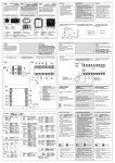
DEALER PREPARATION/INSTALLATION CHECK LIST
Frontier RG5500 Spin/Relief Reel Mower Grinder
THIS CHECKLIST IS TO REMAIN IN OWNER’S MANUAL
It is the responsibility of the dealer to complete the procedures listed below, then
review this checklist with the customer upon the delivery or the sale of this equipment.The installation
training goes over the basic operational functions of the equipment. To ensure adequate training, we
require that the following items are reviewed by your John Deere Dealer. Please check off to ensure
that you understand the following items before the installation training is complete:
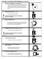
1. Equipment is completely assembled
2. All shields are in place and in good condition.
3. All decals in place and readable. (See pages)
4. Overall condition good (i.e. paint, welds, electrical)
5. Verify there is sufficient electrical power to operate
the machine.
6. Review Operators, Assembly & Service Manuals,
and any additional training material if available.
7. Review proper positioning of reel
8. Explain use of reel grinder relief mechanism
9. Review traverse proximity switch positioning
10. Explain use of reel grinder alignment gage
11. Explain reel grinder spin speed vs. quality
12. Discuss reel grinder set-up chart in manual
13. Review General Maintenance
Dealer's Signature
Purchaser's Signature
Safety
IMPORTANT SAFETY MESSAGE FOR OWNERS/OPERATORS OF REEL GRINDERS
Before operating a reel grinder, an operator must read and
understand all of the information in the owner’s manual and in
the safety signs attached to the product. A person who has not
read or understood the owner’s manual and safety signs is not
qualified to operate the unit. Accidents occur often on machines
that are used by someone who has not read the owner’s
manual and is not familiar with the equipment. If you do not have
an owner’s manual or current production safety signs, contact
the manufacturer or your dealer immediately.
Safety is a primary concern in the design, manufacture, sale,
and use of reel grinders. As manufacturer of reel grinders, we
want to confirm to you, our customers, our concern for safety. We
also want to remind you about the simple, basic, and common
sense rules of safety when using a reel grinder. Failure to follow
these rules can result in severe injury or death to operators or
bystanders.
It is essential that everyone involved in the assembly, operation,
transport, maintenance, and storage of this equipment be
aware, concerned, prudent, and properly trained in safety.
Always use proper shielding as specified by the manufacturer.
Reel grinders are designed for one-man operation. Never
operate the grinder with anyone near, or in contact with, any part
of the grinder. Be sure no one else, including bystanders, are
near you when you operate this product.
Our current production machines include, as standard
equipment, guards or shields for the grinding wheel, safety
signs and an operators manual. Never bypass or operate the
machine with any of the guards or safety device removed.
Following these simple, basic safety rules, as well as others
identified in the owner’s manual and in product safety signs, will
help minimize the possibility of accidents and increase your
productivity in using this product. Be careful and make sure that
everyone who operates the grinder knows and understands that
this is a very powerful piece of machinery, and if used
improperly, serious injury or death may result. The final
responsibility for safety rests with the operator of this machine.
Read and fully understand all the safety practices discussed
on pages 4 and 5 of this manual. All safety rules must be
understood and followed by anyone who works with reel
grinders.
2
TO THE DEALER:
Assembly and proper installation of this product is the responsibility of the John Deere dealer. Read manual
instructions and safety rules. Make sure all items on the Preparation Check List in the Operator’s Manual are
completed before releasing equipment to the owner.
TO THE OWNER:
Read this manual before operating your Frontier equipment. Keep this manual handy for ready
reference. Require all operators to read this manual carefully and become acquainted with all
adjustments and operating procedures before attempting to operate the equipment. Replacement
manuals can be obtained from you selling dealer.
The equipment you have purchased has been carefully engineered and manufactured to provide
dependable and satisfactory use. Like all mechanical products, it will require cleaning and upkeep.
Lubricate the unit as specified. Please observe all safety information in this manual and safety
decals on the equipment.
For service, your authorized John Deere dealer has trained mechanics, genuine Frontier service
parts, and the necessary tools and equipment to handle all of your service needs.
Use only genuine Frontier service parts.
3
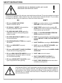
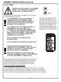
SAFETY INSTRUCTIONS
Safety Awareness Symbols are inserted
into this manual to alert you to possible
Safety Hazards. Whenever you see these
symbols, follow their instructions.
The Warning Symbol identifies
special instructions or procedures
which, if not correctly followed,
could result in personal injury.
!
The Caution Symbol identifies special
instructions or procedures which, if not
strictly observed, could result in damage
to or destruction of equipment.
1. KEEP GUARDS IN PLACE and in working
order.
12. DON'T OVERREACH. Keep proper footing and
balance at all times.
2. REMOVE WRENCHES AND OTHER
TOOLS.
13. MAINTAIN GRINDER WITH CARE. Follow
instructions in Service Manual for lubrication and
preventive maintenance.
3. KEEP WORK AREA CLEAN.
14. DISCONNECT POWER BEFORE SERVICING,
or when changing the grinding wheel.
4. DON'T USE IN DANGEROUS ENVIRONMENT.
Don't use Grinder in damp or wet locations.
Machine is for indoor use only. Keep work area
well lit.
15. REDUCE THE RISK OF UNINTENTIONAL
STARTING. Make sure all switches are OFF
before plugging in the grinder.
5. KEEP ALL VISITORS AWAY. All visitors
should be kept a safe distance from work area.
16. USE RECOMMENDED ACCESSORIES. Consult
the manual for recommended accessories. Using
improper accessories may cause risk of personal
injury.
6. MAKE WORK AREA CHILD-PROOF with
padlocks or master switches.
17. CHECK DAMAGED PARTS. A guard or other
part that is damaged or will not perform its
intended function should be properly repaired or
replaced.
7. DON'T FORCE THE GRINDER. It will do the job
better and safer if used as specified in this
manual.
8. USE THE RIGHT TOOL. Don't force the grinder
or an attachment to do a job for which it was not 18. KNOW YOUR EQUIPMENT. Read this manual
carefully. Learn its application and limitations as
designed.
well as specific potential hazards.
9. WEAR PROPER APPAREL. Wear no loose
clothing, gloves, neckties, or jewelry which may 19. KEEP ALL SAFETY DECALS CLEAN AND
LEGIBLE. If safety decals become damaged or
get caught in moving parts. Nonslip footwear is
illegible for any reason, replace immediately.
recommended. Wear protective hair covering to
Refer to replacement parts illustrations in Service
contain long hair.
Manual for the proper location and part numbers
of safety decals.
10. ALWAYS USE SAFETY GLASSES.
20. DO NOT OPERATE THE GRINDER WHEN
UNDER THE INFLUENCE OF DRUGS,
ALCOHOL, OR MEDICATION.
11. SECURE YOUR WORK. Make certain that the
cutting unit is securely fastened with the clamps
provided before operating.
4
SAFETY INSTRUCTIONS
IMPROPER USE OF GRINDING WHEEL MAY CAUSE
BREAKAGE AND SERIOUS INJURY.
!
Grinding is a safe operation if the few basic rules listed below are followed. These rules are based on material
contained in the ANSI B7.1 Safety Code for "Use, Care and Protection of Abrasive Wheels". For your safety,
we suggest you benefit from the experience of others and follow these rules.
DON'T
DO
1. DO always HANDLE AND STORE
wheels in a careful manner.
1. DON'T use a cracked wheel or one that HAS BEEN
DROPPED or has become damaged.
2. DO VISUALLY INSPECT all wheels before
mounting for possible damage.
2. DON'T FORCE a wheel onto the machine OR
ALTER the size of the mounting hole--if wheel won't
fit the machine, get one that will.
3. DO CHECK MACHINE SPEED against the
established maximum safe operating speed
marked on wheel.
3. DON'T ever EXCEED MAXIMUM OPERATING
SPEED established for the wheel.
4. DON'T use mounting flanges on which the bearing
surfaces ARE NOT CLEAN, FLAT AND FREE OF
BURRS.
4. DO CHECK MOUNTING FLANGES for equal
and correct diameter.
5. DO USE MOUNTING BLOTTERS when supplied
with wheels.
5. DON'T TIGHTEN the mounting nut EXCESSIVELY.
6. DO be sure WORK REST is properly
adjusted.
6. DON'T grind on the SIDE OF THE WHEEL (see
Safety Code B7.2 for exception).
7. DO always USE A SAFETY GUARD COVERING
at least one-half of the grinding wheel.
7. DON'T start the machine until the WHEEL GUARD
IS IN PLACE.
8. DO allow NEWLY MOUNTED WHEELS to run at
operating speed, with guard in place, for at least
one minute before grinding.
8. DON'T JAM work into the wheel.
9. DON'T STAND DIRECTLY IN FRONT of a
grinding wheel whenever a grinder is started.
9. DO always WEAR SAFETY GLASSES or some
type of eye protection when grinding.
10. DON'T FORCE GRINDING so that motor slows
noticeably or work gets hot.
AVOID INHALATION OF DUST generated by grinding and cutting operations. Exposure
to dust may cause respiratory ailments. Use approved NIOSH or MSHA respirators,
safety glasses or face shields, and protective clothing. Provide adequate ventilation to
eliminate dust, or to maintain dust level below the Threshold Limit Value for nuisance
dust as classified by OSHA.
5
TABLE OF CONTENTS
This machine is intended for grinding the reel of reel type mower units ONLY.
Any use other than this may cause personal injury and void the warranty.
!
To assure the quality and safety of your machine and to maintain the warranty,
you MUST use original equipment manufactures replacement parts and have
any repair work done by a qualified professional.
ALL operators of this equipment must be thoroughly trained BEFORE operating
the equipment.
Do not use compressed air to clean grinding dust from the machine. This dust
can cause personal injury as well as damage to the grinder. Machine is for
indoor use only. Do not use a power washer to clean the machine.
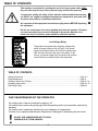
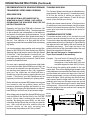
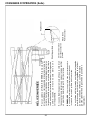
Low Voltage Relay
The grinder is equipped with a high-low voltage relay
which is factory preset at 100-140 VAC. If the power
supply line does not deliver 100-140 VAC power under
load, the relay will open and trip out the starter. If this
occurs, your power supply line is incorrect and must be
correct before proceeding further with the grinder.
TABLE OF CONTENTS
Safety Instructions .................................................................................................................
Daily Maintenance .................................................................................................................
Getting to Know Your Grinder ................................................................................................
Operating Instructions ............................................................................................................
Reel Setup Chart ...................................................................................................................
Page 4 - 7
Page 6
Page 8 - 14
Page 15 - 27
Page 28
DAILY MAINTENANCE BY THE OPERATOR
On a daily basis, clean the machine by wiping it off.
On a daily basis, remove all grinding grit from the grinding shaft, traverse shafts, and tooling
bar area.
On a daily basis, inspect the machine for loose fasteners or components.
Contact your company's Maintenance Department if damaged or defective parts are found.
!
DO NOT USE COMPRESSED AIR TO CLEAN
GRINDING DUST FROM GRINDER.
6
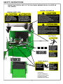
SAFETY INSTRUCTIONS
PLEASE TAKE SPECIAL NOTE OF THE FOLLOWING WARNING DECALS LOCATED ON
THE GRINDER.
GENERAL INFORMATION
GRINDING WHEEL RPM
ELECTRICITY
SHARP OBJECTS
Label Sheet
(English and Spanish)
Part Number 5NT155301
(English and French)
Part Number 5NT155302
7
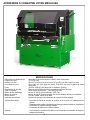
GETTING TO KNOW YOUR GRINDER
SPECIFICATIONS
Traversing Switches
Overall Width
Overall Height
Overall Depth
Weight
Base Construction
Carriage Rails
Grind Head Motor
Spin Motor
Sound Level
Auto Traverse
Solid state, non-contacting proximity switches.
71" [181 cm]
69" [175 cm] with door closed, 87" [221 cm] with door open
42" [107 cm]without workstation, 79" [201 cm] with optional workstation
1450 lbs. [658 kg] 1650 lbs shipping weight [748 kg]
Precision heavy duty reinforced welded steel base
Precision Ground, Hardened Steel - 1.000 Dia. [25.4 mm]
1HP AC Motor, 3450 RPM
.20 HP Fan Cooled Variable Speed DC Motor
More than 75 Dba, Less than 95 Dba
Belt driven with easy to engage clamp system
Control System
*Safety grind motor and spin drive door interrupt switches
*Reversible Spin drive for variable speed Spin or variable torque relief functions
*Variable speed traverse control.
Options:
*Manual Winch and Boom Kit, Electric Winch and Boom Kit or Lift Platform.
8
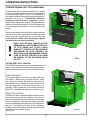
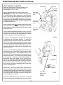
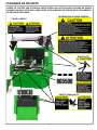
GETTING TO KNOW YOUR GRINDER (Continued)
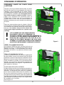
CONTROL PANEL COMPONENT IDENTIFICATION
Review the following control panel component descriptions before proceeding with the instructions
SYSTEM START PUSHBUTTON
The green pushbutton is the system start switch. Pushing
it will engage the magnetic starter and power the control
panel. The magnetic starter will not engage unless the
emergency stop pushbutton is pulled out and the grinding
motor switch and spin motor switch are turned off.
GRIND SELECTOR SWITCH
Variable speed spin
Switch must be up to perform
spin grinding operations.
Variable Torque Relief
Switch must be down to perform
relief grinding operations.
SPIN DRIVE ROTATION SWITCH
Forward / Off / Reverse
This switch reverses the direction of the spin
drive motor.
IMPORTANT: Because the spin drive motor
can be flipped on the horizontal adjustment
arm, the direction may be opposite of what
is shown on the decal.
SPIN SPEED POTENTIOMETER DIAL RPM
Adjusts the speed of reel rotation when you
have the grind selector switch set at variable
speed spin.
GUARD DOORS MUST BE SHUT FOR SPIN
DRIVE TO OPERATE.
9
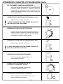
GETTING TO KNOW YOUR GRINDER (Continued)
PUSH-PULL EMERGENCY STOP BUTTON
Push in to cut all power to the control panel functions.
This removes power from all motors, including the
grinding motor, traverse motor, spin motor, etc. To
restore power, pull up on button and press the Start
button.
SPIN MOTOR SWITCH On / Off
!
Turn the Spin Motor on and off.
GUARD DOORS MUST BE SHUT FOR GRIND
MOTOR TO OPERATE.
RELIEF TORQUE DIAL
Adjusts the Spin Drive Motor torque (the torque holding
the reel blade to the relief finger) when Grind Selector
Switch is set at variable Torque Relief.
GRINDING WHEEL MOTOR SWITCH On / Off
Turn the Grinding Wheel Motor on and off.
!
GUARD DOORS MUST BE SHUT FOR GRIND
MOTOR TO OPERATE.
TRAVERSE MOTOR SWITCH
Turns the traverse drive motor ON/OFF.
TRAVERSE SPEED POTENTIOMETER
DIAL - FT / MIN
Adjusts the speed of the left & right
movement of the Grinding wheel.
TRAVERSE REVERSE SWITCH
Reverses the direction of the grinding
head if pushed when the head is moving.
10
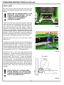
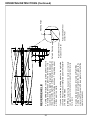
GETTING TO KNOW YOUR GRINDER (Continued)
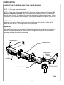
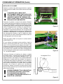
FRONT AND REAR MOWER MOUNTING
The mowing unit should be placed in the machine with
the rear roller on the table and front roller held in the
front tooling. The front tooling can be moved side to
side along the tooling bar so they can be positioned as
far apart as necessary to accommodate all reel widths.
Decals on the tooling bar make it easy to position the
tooling based on the width of the reel. To move the
tooling, loosen the knob located at the front of the
tooling base and slide tooling along the tooling bar. The
tooling should be located as close to the frame as
possible leaving the maximum room to use the
position gauge (the gauge will be discussed in the
alignment section). The horizontal position is attained
by using the hand wheel located at the front of the
tooling. If you are grinding a Quick Adjust mowing unit
(QA7 or QA5), use the decals located on the tooling to
quickly position the reel. There are two positions for
each reel depending on how the front roller is mounted.
See FIG 2.
If you are using the all-position brackets, the vertical
and horizontal position can be adjusted by loosening
the knobs located on the side of the tooling and
moving to a new set of pins.
FIG. 1
Verify that the reel is positioned properly for the spin
wheel and relief wheel by checking the travel limits,
both wheels will need to have clearance to come off
the reel on both sides. Checking during setup will
eliminate the need for major adjustments and
alignments when going from spin grinding to relief
grinding. When the mower is in place lock it into
position by tightening all knobs. Lift the rear roller onto
the angled bracket and clamp the roller firmly by
squeezing the clamp handle.
QA5 AND QA7 REEL
LOCATION DECAL.
TOOLING POSITION
DECAL
FIG. 2
REEL POSITION
The reel should be positioned so that it is at a one o’clock
or 30° angle position in reference to the grinding wheel.
See FIG 3. If the all-position brackets are used try to
position the unit so that the bottom of the reel is
between 1.50-2.00" [38-51MM] off the table. When
using the roller mount style tooling try to maintain the
one o’clock position and check for clearance between
the reel and grinding wheel. Verify that the proper relief
angle can be achieved with this setting and make
any adjustments if necessary.
If you are grinding a QA7 or QA5 reel using the roller
style mounts, use the decals located on the tooling to
obtain the optimal position to grind the reel. See fIG 2
FIG. 3
11
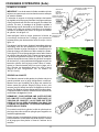
GETTING TO KNOW YOUR GRINDER (Continued)
TRAVERSE ENGAGEMENT AND RELEASE
The belt that drives the relief and spin hubs left and
right can be engaged and released by flipping the clamp
located on the bottom of the grinding head assemblies.
Moving the lever to the left will engage the belt and
moving it to the right will disengage the belt. The tip
can be adjusted if necessary to increase or decrease
the tension on the belt. See adjustments in the
service manual for more details.
THE BELT CLAMP TIP IS
ADJUSTED AT THE FACTORY TO
ALLOW THE BELT TO SLIP IF THE
HUB COMES IN CONTACT WITH
SOMETHING. CAUTION SHOULD
BE USED WHEN ADJUSTING THE
TIP. IF THE CLAMP IS OVERTIGHTENED, THE BELT WILL
NOT SLIP WHICH MAY CAUSE
DAMAGE TO THE MACHINE OR
REEL.
TRAVERSE BELT
ENGAGEMENT
CLAMP TIP
TRAVERSE BELT
FIG.4
LEVER
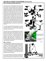
TRAVERSE PROXIMITY SWITCHES
Two movable proximity switches determine the left and
right limits of grinding head assembly. An LED on the
switch lights when the grinding head gets close to the
head of the proximity switch. The sensors are mounted
in the Proximity Brackets located on the traverse shafts.
The brackets can easily be slid along the shafts for quick
and easy travel limit adjustments. When switching from
the spin mode to the relief mode, the brackets will need
to be lifted off the shafts and snapped back on the shafts
in the proper position.
TRAVERSE
RIGHT LIMIT
PROXIMITY
SENSOR
TRAVERSE
LEFT LIMIT
PROXIMITY
SENSOR
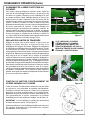
DUST
DEFLECTOR
RELIEF GRINDING
WHEEL & HUB
SPIN GRINDING
WHEEL & HUB
SPIN/RELIEF GRINDING HEAD
FIG. 5
This grinder is equipped with separate spin and relief
grinding wheels. When the setup is done properly the
reel will be only need to be positioned and aligned once
for both cycles. The spin wheel is located on the right
side of the machine and is wider than the relief wheel.
Move the wheel that is not being used as far to that side
as possible to give the maximum amount of room to
setup and operate the machine. The proximity
sensors must be moved so that the wheel in use is
between the two sensors. Make sure that the wheel
that is not in use is not engaged to the drive belt.
12
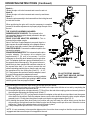
GETTING TO KNOW YOUR GRINDER (Continued)
RELIEF ANGLE ADJUSTMENT
Rotating the finger system around the grinding wheel will
change the relief angle. By loosening the large ratchet
handle the finger system can be rotated to achieve the
factory angles, or whatever angle you select. See FIG. 6.
By rotating the finger forward the relief angle will decrease
and rotating it rearward the relief angle will increase.
Retighten the ratchet handle when adjustment is correct.
RELIEF WHEEL DIAMETER ADJUSTMENT
As the wheel wears, the finger system will need to be
adjusted to maintain the correct gap between the fixed
finger and wheel. To move the finger system loosen the
small ratchet handle. See FIG. 6. The gap between the
fixed finger and the grinding wheel should be between
.06" [1.5 mm] and .18" [4.6 mm] depending on the amount
of existing relief on the reel. Retighten the ratchet handle
after the adjustment is made.
INDEX FINGER ADJUSTMENTS
The Relief Assembly includes two fingers. See FIG. 6. The
Fixed Relief Finger hold the blade in position during the
relief grind process. The Movable Index Stop Finger moves
from the Relief Finger Side (back side) of the reel blade
when traversing from right to left, to the grinding wheel
side (front side) of the reel blade when traversing from left
to right. The indexing finger allows the grinder to index to
the next blade automatically during the relief grind.
Improper adjustment of the relief fingers assembly may
result in a bad grind or possibly damage to the reel or
machine.
FIXED FINGER
INDEX STOP
PIN
MOVABLE
INDEXING
FINGER
INDEX FINGER
STOP POSITION
KNOB
WHEEL DIAMETER
ADJUSTMENT
HANDLE
RELIEF ANGLE
ADJUSTMENT
HANDLE
FIG. 6
The Index Finger Stop Position Knob adjusts where the
Index finger stops when the reel blade indexes. See FIG. 6.
Proper position of this stop is critical to allow the reel blade
to smoothly transition from the Index Finger to the Fixed
Finger.
IMPORTANT! After adjusting the Index Finger Stop
Position Knob there should be 1/32" [0.8 mm] clearance
between the index finger and the reel blade when you push
on the index finger. This will allow the Fixed Relief Finger
to guide the reel blade during the relief grind cycle. The
Reel blade should never be riding on the Index Finger
when grinding.
The Index Stop Pin is height adjustable. It should be
adjusted to catch the reel blade and still leave enough
clearance to the reel spider after the relief is ground to the
depth required.
There is a forward position stop on the Finger system
located near the pivot point of the Index Finger. This will only
need to be adjusted if there is a clearance issue with the
finger when it travels forward. See FIG 7.
13
INDEX FINGER
FORWARD STOP
POSITION
SETSCREW
FIG. 7
GETTING TO KNOW YOUR GRINDER (Continued)
ALIGNMENT GAUGE
REEL CENTER SHAFT
A properly ground reel should be cylindrical. All taper
must be ground out of the reel. To ensure the reel will
be ground correctly it MUST be aligned precisely prior
to grinding. The digital alignment gauge is used for
accurate reel setup. The gauge is used for setting the
horizontal alignment and checking for taper within
thousands of an inch. The digital gauge allows you to
measure one end of the reel by extending the slide rail
until you make contact with the center shaft of the reel.
See FIG. 8. By measuring at the far left and the far right
on the center shaft you can adjust the horizontal
alignment using the front tooling adjustment knobs until
the alignment is within .005 inches [.13mm].
INDICATOR SLIDE RAIL
IN / mm
ZERO RESET
ON/OFF
FIG. 8
When this is completed, you can then reset the gauge
to zero on the center shaft, retract the gauge slide
and measure the outer surface of a reel blade. By
comparing the readings on the left side of the reel to
the right side of the reel, you can determine exactly how
much taper you have in the reel. Compensating for
taper will be explained later in the grinding procedure.
NOTE: The gauge can be set for both inch and metric
readout.
14
OPERATING INSTRUCTIONS
PREPARE MOWING UNIT FOR SHARPENING
Always follow the procedures specified in the cutting
unit manual when preparing the unit for sharpening. It
is recommended that the reel to be sharpened is
thoroughly cleaned. Remove the wheels and bed bar, if
possible, from the reel. The bedknives should be
sharpened when the reel is sharpened. Inspect,
adjust and/or replace any worn or damaged bearings.
Make sure the reel bearings are in good working condition and adjusted properly so the reel turns easily by
hand.
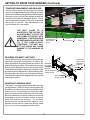
Because this grinder mounts the reel using the reel rear
roller and front roller if applicable, the bearings in the
rollers must be in good repair with no free play. The
front and rear rollers must be properly aligned
parallel to the reel prior to grinding.
REELS WITH EXCESS TENSION ON THE
BEARINGS WILL BE EXTREMELY DIFFICULT
TO SPIN GRIND AND COULD CAUSE
DAMAGE TO THE REEL OR THE SPIN DRIVE
MECHANISM ON YOUR GRINDER. NO
MORE THAN 25. IN. LBS MAXIMUM TORQUE
LOAD TO ROTATE THE REEL IS ALLOWED
OR DAMAGE TO THE SPIN DRIVE COULD
OCCUR.
!
FIG. 9
LIFTING REEL INTO POSITION
The RG5500 grinder does not come standard with a lift
device. If the facility does not have a lift, it is recommended
that the winch and boom kit or Rear Lift Platform is used.
.
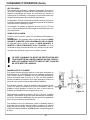
WINCH & BOOM KIT
The Winch & Boom kit mounts to the back right side of
the cabinet. When using the Winch & Boom, position
the cutting unit behind the machine and secure the
spreader bar to the cutting unit. Use the winch to lift the
unit and swing the reel into the working area of the
machine. (Refer to manual in kit for further instructions.)
See FIG. 9 - Available with a Manual or Electric winch.
REAR LIFT PLATFORM
The Rear Lift Table is a portable platform that can be used
to raise the reel up level to the grinder. The reel can be
rolled onto the platform with the front of the reel facing the
front of the grinder. With rear roller clamp removed the
reel can be rolled from the platform into the machine from
the rear. The Platform Lift uses a 12V rechargeable
system to power the platform and can be moved around
the facility on the 4 caster wheels .
See FIG. 10
15
FIG. 10
OPERATING INSTRUCTIONS (Continued)
INSTALL REEL
Move the reel to the approximate position having the rear
roller on the tabletop, and front roller on the front roller
Mounts.
!
MAKE SURE THE GRINDING WHEEL IS LOW
ENOUGH TO CLEAR THE REEL. YOU CAN
LOWER THE GRINDING WHEEL BY
TURNING BOTH HANDWHEELS
COUNTERCLOCKWISE.
Position front reel in the center of the machine. Move the
roller mounts as far out as possible to the ends of the front
roller. (See FIG 11). Use the decals on the tooling bar to
aid in the positioning of the front tooling. Check for
clearance to the tooling, front roller and frame with both
the spin and relief wheels. This will ensure that you will
not have to move the reel between the spin and relief
grinding. NOTE: On large reels it may be necessary to
offset the reel slightly from center to allow the spin drive to
be mounted on the appropriate side of the cutting unit.
FIG. 11
Place the rear roller onto the rear roller clamp.
(See FIG 12).
If using the all-position brackets, set the vertical height of
the clamps so that the bottom of the reel is 1.5-2.0 inches
[38-51mm] above the table. It is also recommended to
mount the support arm with as little extension from the all
position bracket as possible leaving just enough clearance
for mounting the reel in the “V” of the support arm.
Position the reel in and out by adjusting the front
handwheels. The reel should be positioned so that the
reel shaft is located at a 1 o’clock or 30° position to the
grinding wheel. See figure 13. If there are clearance
issues the reel can be moved forward or backward to
resolve this issue. If you are grinding a QA5 or QA7 reel
use the decals located on the tooling to quickly locate the
reel in the optimal position. See FIG 2. After the reel is
positioned correctly lock down the front roller and tighten
the rear clamp. Make sure all knobs are tight before
grinding.
!
FIG. 12
30° angle or
FIRMLY TIGHTEN ALL LOCKING KNOBS
BEFORE GRINDING. ANY LOOSE KNOBS,
CLAMPS OR BEARINGS WILL ADVERSELY
AFFECT THE GRIND QUALITY.
FIG. 13
16
OPERATING INSTRUCTIONS (Continued)
ALIGN THE REEL
IMPORTANT: When measuring to the reel center shaft
always make sure you are contacting an area free of dirt
and grass.
The digital gauge horizontal extension bracket is vertically
adjustable to allow the digital gauge to be positioned to
avoid any reel frame member. In addition, the mounting of
the vertical slide to the horizontal weldment has three
positions. Removed the knob on the side to adjust the tilt
of the vertical slide if necessary to avoid a reel frame
member. See FIG. 14.
Before aligning the cutting unit, loosen the horizontal
locking knobs on the tooling, to allow the cutting unit to be
adjusted in the horizontal plane. See FIG. 14.
GAUGE ANGLE
ADJUSTMENT
T-KNOB
FORWARD AND
BACKWARD
MOUNTING HOLES
GAUGE VERTICAL ADJUSTMENT T-KNOB
HORIZONTAL
ADJUSTMENT
HANDWHEEL
GAUGE
BASE
TOOLING BAR
POSITION KNOB
HORIZONTAL
LOCKING T-KNOB
FIG. 14
To align the cutting unit, move the digital gauge assembly
as far as possible to the left side of the reel. Extend the
digital gauge making sure the tip of the gauge is centered
on the reel center shaft. See FIG 15. With the gauge
pressed against the reel center shaft, set the gauge to
zero. Retract the gauge and move to the right side of the
reel and measure to the center of the reel shaft. Do not
rotate the reel shaft except for a minimum amount if there
are clearance issues to the reel blades. With the gauge
against the center shaft, adjust the horizontal handwheel
until the gauge reads zero. Repeat adjustments going
from one side to the opposite side until the alignment is
within .005" [.13 mm].
CHECKING FOR TAPER
First, measure the left side of the reel as far to the left as
possible with the digital alignment gauge, make sure the
tip of the gauge is centered on the reel center shaft. Set
the gauge to zero, then measure to the edge of one blade.
Remember or write this number down. Move to opposite
side and do the same thing. Compare the two numbers;
the difference is the amount of taper in the radius of the
wheel.
FIG. 15
NOTE: TO OBTAIN A CORRECT TAPER READING TO
BE USED WITH THE TAPER CHART LATER, THE
READING MUST BE TAKEN AS CLOSE TO THE
ENDS OF THE REEL AS POSSIBLE GIVING THE
MAXIMUM DISTANCE BETWEEN READINGS.
To remove the taper in the reel, the side of the reel that is
larger will need to be infed heavier to remove this extra
material.
Remove the gauge and store the digital gauge on the pin
located on the front right side of the machine. The gauge
base can be placed inside the machine out of the way.
17
FIG. 16
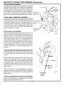
OPERATING INSTRUCTIONS (Continued)
ALIGNMENT OF GRINDING SHAFT TO REEL
To align the grinding shaft to the reel bring the shaft up so that
the spin wheel is about ¼ inch [6 mm] from the reel blades.
Move the spin wheel to one side of the reel and raise the
grinding shaft until the wheel just touches the blade. Move
the wheel to the other side of the reel and bring the shaft up
until the wheel just touches. Recheck from side to side and
make minor adjustments until the wheel touches the same
on both ends of the reel. The grind shaft is now aligned
vertically to the reels outer diameter. Zero the gauges located
on the vertical adjustment housing. Check for high spots in
the reel by moving the wheel the length of the reel while
spinning the reel. If there are high spots lower the shaft equally
on both ends and zero out the gauges again.
FIG. 17
!
SETTING THE TRAVERSE LIMITS
Move the grinding wheel to the right until the wheel has
cleared the reel by approximately ¼ inch [6 mm] (if
clearance to the frame allows). Disengage both the relief
and Spin grinding assemblies from traverse belt. Turn the
Traverse speed potentiometer to zero and turn on the
Traverse Motor Switch. This will activate the proximity
sensors. Move the right Traverse Travel Limit switch in until
the light on the proximity sensor illuminates. Move the wheel
to the opposite end, clearing the reel as mentioned above,
and set the left Traverse Travel Limit Switch. (Fig 17)
Engage the traverse belt and slowly turn the Traverse Speed
up. Allow the wheel to traverse from end to end to verify the
switches stop and reverse the direction of the grinding wheel.
Verify that the grinding wheel travels fully off the reel at each
end. Note: If the reel will hit the frame, then adjust travel
sensors so the wheel does not contact the frame.
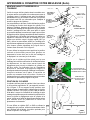
ATTACHING THE VARIABLE SPEED SPIN DRIVE
UNIT TO THE REEL
IF THE REEL FRAME EXTENDS
BELOW THE REEL ITSELF, MAKE
SURE THE STOP IS SET SO THAT
THE GRINDING WHEEL DOES NOT
RUN INTO THE FRAME WHILE
GRINDING.
FIG. 18
The spin drive unit attaches to the end of the reel shaft or a
drive system component. Consult the cutting unit manual for
proper spin drive placement and attachment. Determine which
side to mount the spin drive. This will generally be the same
drive system component used for backlapping. See FIG. 18.
IMPORTANT: When spin grinding, the reel should turn in
the same direction as the grinding wheel. See FIG. 19.
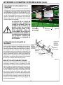
Before positioning the spin unit let us familiarize ourselves
with the available adjustments and coupler/drive assemblies.
See FIG. 20.
18
FIG.19
OPERATING INSTRUCTIONS (Continued)
Knob A—
Allows the spin unit to be loosened and moved in and out.
Knob BAllows the spin unit to be loosened and moved up and down.
Knob C –
Allows the spin assembly to be loosened from the tooling bar and
moved side-to-side.
When positioning the spin unit it may be necessary to complete
several of the above adjustments to properly align the spin unit to
the reel.
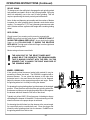
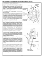
THE COUPLER ASSEMBLY INCLUDES:
RUBBER SLEEVE COUPLER: This is placed in the
corresponding flange coupler already mounted in the spin
drive shaft. See FIG. 21.
DRIVE COUPLER ADAPTER ASSEMBLY: This is
mounted to the rubber coupler.
Note: If the Drive Coupler Adapter is removed, there is a
short square drive shaft attached to the Adapter Sleeve.
This can be used with a socket if there is limited space.
ADAPTER SLEEVE: Connects the rubber coupler to the
square drive adapter.
SQUARE DRIVE ADAPTER: This is inserted into the drive
coupler adapter. The square drive adapter has
approximately 2" [51 mm] of movement. It will be
necessary to move this when attaching reel to spin drive
unit. This adapter shaft has a groove machined into it on
the opposite end of the snap ring. This groove is there to
advise that you have reached the maximum extension of
the square drive shaft. If you cannot connect the reel
without extending past this groove, then the spin unit must
be repositioned on the tooling bar (Knob C). A 1/2"
[12.7 mm] square drive socket or reel drive adapter is used
to connect the square drive adapter to the reel.
NOTE: The 1/2" [12.7 mm] square drive socket or adapter
that is placed on the reel when spin grinding is NOT included
with the grinder. See next page for details
FIG.20
FIG. 21
DO NOT EXTEND SQUARE
SHAFT PAST GROOVE, INSTEAD
REPOSITION SPIN UNIT.
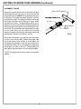
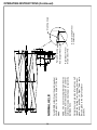
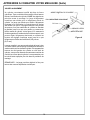
The following procedures will make setting up the spin drive unit easier.
1. Move spin drive unit close to the reel. Align the shaft on the spin drive with the nut on reel by completing the
necessary adjustments discussed above.
2. Now slide the spin drive unit approximately 7" [18 cm] from the reel drive coupling point and securely fasten to
the tooling bar tightening the locking knob. (Knob C)
3. Place the proper 1/2" [12.7 mm] square drive socket or adapter on the reel drive nut and then insert the square
drive shaft into the socket. Place the adapter sleeve over the drive shaft and insert the drive coupler adapter
assembly into it. Finally place the rubber coupler onto the drive coupler adapter. See FIG. 21.
4. By holding the square drive shaft firmly into position with your left hand you will be able to move the other
components to the right and insert the rubber coupler into the flange on the spin drive unit. When this is done
tighten the T-Knob on the adapter sleeve to hold all parts in place.
5. Finally readjust the spin drive unit if it is not in alignment.
NOTE: It is not necessary to have perfect alignment but it must be close enough so that the coupler remains
engaged and that excess torque is not applied to the reel.
19
OPERATING INSTRUCTIONS (Continued)
REEL DRIVE ADAPTERS
This grinder is equipped with an adapter that transfers the rotation from the spin drive gear box coupling to a
1/2" male square. To operate the grinder you need an adapter from this 1/2" male square to the reel shaft.
These adapters are NOT included with this grinder.
Most cutting units In recent years have a male or female spline on the end of the reel shaft that connects to
a hydraulic or electric motor shaft.
If you have a reel shaft that has an internal threaded end which you can access, install a hex head bolt or
socket head screw of that thread size with a jam nut very tight so it does not loosen while spin grinding and
then drive with a 1/2" drive socket for that hex or hex key size.
JOHN DEERE REELS
COUPLERS- The external spline shafts use a female splined coupler between the reel shaft and the male
splined hydraulic motor shaft. The spline is either an 8,9 or 11 toothed spline. Our recommendation is to
purchase the female splined coupler from John Deere and weld it to a short 1/2" square socket extension.
Note: The 8 tooth spline adapter can be used with a Square Socket Drive Adapter [3/8" square male to 1/2"
square female] without welding.
REEL DIA REEL TYPE
5"
G, M
7"
H
7"
26H
8"
ESP
5"
WBGM
5"
QA5
7"
QA7
Recomendation
Has an 8-T, External shaft. Use coupler AET11038
Has an 11-T, External shaft. Use coupler TCA12581
(NOTE: THIS CAN ALSO BE DRIVEN WITH A 1.25 HEX SOCKET)
Has a 9-T, External shaft. Use coupler AET11310
(NOTE: THIS CAN ALSO BE DRIVEN WITH A 1.25 HEX SOCKET)
Has a M16 X 2, External shaft. Use nut A31869 and drive with
a 24mm Hex Socket.
Use a 3/8"-24 UNF Bolt, and drive with a 9/16 Hex Socket
Has an 8-T, Internal Spline shaft. Use part AMT3022, to make
an adapter.
Has an 11-T, Internal Spline shaft. Use a 1.25 Hex Socket or
make and adapter from part TCA18958.
TORO EQUIPMENT:
Toro uses an 8 tooth female spline or a 9 tooth female spline on their reels. The 8 tooth female spline can be affectively
driven with a Square Socket Drive Adapter [3/8"square male to 1/2" square female]. The 9 tooth spline requires an
adapter. Our recommendation is to purchase adapter Toro tool part numberTOR-4074 available from
K-Line Industries, Inc. 315 Garden Ave. Holland, MI 49424.
JACOBSEN EQUIPMENT:
Below is a list of drive systems based on the cutting units:
* 5" reel units can be driven from the non hydraulic motor end of the reel. Install a 3/8" bolt in the end of the reel shaft
with a jam nut very tight so it does not loosen while spinning. Use a 9/16" socket to drive. They can also be driven from
the hydraulic motor end by pressing a Square Socket Drive Adapter [3/8" square male to 1/2" square female] into the
splined reel coupling Jacobsen part number 337370 and use this pressed assembly as the adapter.
* 7" reel units can be driven from either end. The reel unit has a coupler attached to the reel shaft a both ends. Purchase
Jacoben part number 4102440 Reel Motor Shaft and weld the hydraulic motor shaft form the kit to a 1/2" socket and use
this weldment as the adapter.
* Tri-King reel units can be driven on older pulley drive units with a 9/16" socket on the 3/8" bolt that holds the pulley. On
newer splined units, purchase the splined reel coupling Jacobsen part number 132002 and press a Square Socket Drive
Adater [3/8" square male to 1/2"square female] into the splined reel coupling and use this assembly as the adapter.
20
OPERATING INSTRUCTIONS (Continued)
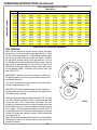
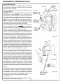
RECOMENDATION FOR SPIN DRIVE RPM AND
TRANSVERSE SPEED WHEN GRINDING
SPIN DRIVE RPM
SPIN DRIVE RPM IS VERY IMPORTANT IN
ACHIEVING A QUALITY GRIND. USE CARE IN
ESTABLISHING THE SPIN DRIVE RPM, PER THE
INSTRUCTIONS BELOW.
Generally, the Spin Drive RPM will be between 180
RPM (45%) and 380 RPM (100%). The speed required
to spin a specific reel is dependant on reel diameter,
the number of reel blades, and reel hardness. For all
reels, there is an optimum Spin Speed where there is
an AGGRESSIVE, yet smooth grind as you spin grind
the reel. Your objective is to spin grind the reel as
aggressively and as fast as possible while maintaining
top quality.
It is recommended to start grinding each reel at a Spin
Speed of 200 RPM (50%) and evaluate the RPM by
adjusting higher and lower to optimize the Spin Speed
for that reel. If the Spin Speed is incorrectly set, you
can experience two problems, grinding wheel
dressing or grinding wheel resonance. Each of these
problems is explained below.
On some reels, especially small diameter high blade
count reels if the Spin Speed RPM is set too high, the
reel can act as a dresser to the grinding wheel. There
can develop what appears to be a very aggressive
grind (as if the infeed has self infed) and then a
sudden stop of grinding with no grinding wheel to reel
contact. If this occurs, your Spin Speed was set too
high and you effectively dressed your grinding wheel.
Some reels have a resonant RPM where the reel goes
into harmonics with the grinding wheel and the
resonance vibrates the grinder and results in a very
bad grind. By changing the Spin Speed to a higher or
lower RPM you will move out of the resonant range.
After determining the best Spin Speed RPM for a reel,
note the RPM on the "Set-up Chart" in the "NOTES"
section. (Set-up chart is located at the back of this
manual) By noting the correct RPM, you will avoid
evaluating the Spin Speed the next time you grind the
reel. Also note the spin drive position using the
position decals on the spin mounting and
documenting the position on the "Set-up Chart".
TRAVERSE DRIVE RPM
The Traverse Speed potentiometer is adjustable from
approximately 5 feet per minute [1.5 meters per minute]
to 20 feet per minute (6 meters per minute). It is
recommended to grind between 15 and 20 feet per
minute (4 and 6 meters per minute).
Grinding at a slower traverse speed, 10 feet per minute
(3 meters per minute) as an example, will give a better
finish but will extend the grind cycle time. Grind finish
versus grind cycle time is controlled by the choice of
the operator.
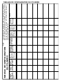
COMPENSATING FOR TAPER.
To maintain the best quality of cut, the taper in a reel
must be removed returning the reel to a true cylinder.
To remove the taper that was measured with the gauge
(as discussed previously in Checking For Taper Section)
first align the reel to the shaft by the touch method (as
discussed previously). Then drop the side of the
grinding shaft that is high (the smaller side of the reel)
the amount suggested in the chart
[See chart on next page or Compensation for
Taper Chart located on the machine].
Example: For a reel that is 22 inches [56 cm] long
with a measured taper of .12" [3 mm],
the adjuster on the smaller side of the reel
would be dropped to read-.546 [13.9 mm].
This will bring the grinding shaft parallel to the reel
center shaft. Zero out the digital gauges located on the
vertical adjustment towers and infeed both side equally
until the wheel just touches the large side of the reel.
Zero the gauges again, you are now ready to grind and
remove the taper. When grinding, the wheel will only
make contact with the larger side of the reel and will
gradually grind more as the larger areas are ground
away. The reverse button may be used to help speed
of this process. Grind until full contact is made across
the entire length of the reel, and the reel is sharp the
entire width of all blades.
AMOUNT
OF TAPER
IN SHAFT
21
AMOUNT OF
TAPER IN REEL
OPERATING INSTRUCTIONS (Continued)
TAPER ADJUSTMENT SETUP CHART
MEASURED TAPER
REEL WIDTH
0.005
0.010
0.015
0.020
0.025
0.030
0.035
0.040
0.045
0.050
0.060
0.070
0.080
0.090
0.100
0.120
16
0.033
0.066
0.100
0.133
0.166
0.199
0.233
0.266
0.299
0.332
0.399
0.465
0.532
0.598
0.665
0.798
18
0.029
0.058
0.086
0.115
0.144
0.173
0.202
0.231
0.259
0.288
0.346
0.403
0.461
0.519
0.576
0.692
20
0.025
0.051
0.076
0.102
0.127
0.153
0.178
0.203
0.229
0.254
0.305
0.356
0.407
0.458
0.508
0.610
22
0.023
0.045
0.068
0.091
0.114
0.136
0.159
0.182
0.205
0.227
0.273
0.318
0.364
0.409
0.455
0.546
24
0.021
0.041
0.062
0.082
0.103
0.123
0.144
0.165
0.185
0.206
0.247
0.288
0.329
0.370
0.412
0.494
26
0.019
0.038
0.056
0.075
0.094
0.113
0.132
0.150
0.169
0.188
0.225
0.263
0.301
0.338
0.376
0.451
28
0.017
0.035
0.052
0.069
0.086
0.104
0.121
0.138
0.156
0.173
0.207
0.242
0.277
0.311
0.346
0.415
30
0.016
0.032
0.048
0.064
0.080
0.096
0.112
0.128
0.144
0.160
0.192
0.224
0.256
0.288
0.320
0.384
32
0.015
0.030
0.045
0.060
0.075
0.089
0.104
0.119
0.134
0.149
0.179
0.209
0.238
0.268
0.298
0.358
Small side of reel downward adjustment.
SPIN GRINDING
After the reel has been aligned and the taper has been
adjusted for, you are now ready to spin grind the reel. Close
the front and rear guard doors. (The grinding wheel and spin
motors will not work unless the doors are closed.) Position
the spin/relief selector switch to the spin position. Turn on
the Grinding Motor and the Spin Drive Motor switch. Set the
spin speed at approximately 200 rpm (Refer to Spin Drive
RPM on pervious page). Make sure spin rotation is the same
as the grinding wheel – clockwise (CW) looking from right
end. See FIG 22.
IMPORTANT: When the reel turns in the same rotation as
the grinding wheel, the point of contact where they meet is
in opposite directions.
Turn on the traverse drive motor switch and turn the speed
dial up to approximately 15- 20.
IMPORTANT: If the grind starts getting heavier, adjust the
grinding head down until you can travel the full length of the
reel without heavy grinding.
When grinding, infeed the wheel approximately .005” [.13 mm]
at a time. Allow the grinding wheel to travel back and forth
across the reel 2 to 3 times before infeeding. The spin
grinding is completed when full contact is made across the
entire length of the reel, the entire width of all blades and the
reel is sharp. The last passes should be a normal .005 [.13
mm] infeed grind at a slow traverse speed (approx. 8 feet per
minute [2.5 meters per minute] or slower). After the last pass
turn the grinder off.
(Note: Due to the positioning of the reel to the 1 o’clock position,
infeeding the wheel .015 inches [.38 mm] will remove .010
inches of material. )
22
FIG.22
OPERATING INSTRUCTIONS (Continued)
RELIEF GRIND
To change over to the relief grind, disengage the spin grinding wheel
hub assembly and park it as far to the right as possible. Bring the
relief hub assembly over to the reel for relief grinding. This will
require repositioning the travel proximity switch brackets.
Note: As the reel diameter gets smaller and the number of blades
increases the relief grinding wheel diameter works better when
smaller. For example a 5" [127 mm] diameter greensmower reels
with 11 blades achieve a greater relief angle with a smaller grinding
wheel.
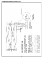
REEL SPIRAL
Check to see if your mowing unit is normal or reverse helix.
NOTE: As you look into the guide finger on THE NEXT PAGE, IT
SHOWS THE NORMAL REEL HELIX. As you look into the guide
finger on the FOLLOW PAGE, IT SHOWS THE REVERSE
REEL HELIX. The high point of the relief finger is on the right hand
side of the grinding wheel.
Most mowing units are normal helix.
!
THE HIGH POINT OF THE RELIEF FINGER MUST
ALWAYS BE AT THE CORNER OF THE GRINDING WHEEL
THAT IS MAKING CONTACT WITH THE REEL. ON THIS
GRINDER THAT IS ALWAYS THE RIGHT HAND SIDE OF
THE GRINDING WHEEL.
WHEEL DRESSING
If the grinding wheel becomes loaded with material it may be
necessary to dress the wheel. The RG5500 is supplied with a
diamond dresser. To use, place the dresser on the spin drive
horizontal arm in the area where the wheel is to be dressed.
Adjust the dresser to the appropriate position and angle. Raise
the grinding wheel so it is nearly touching the dresser.
For dressing the spin grinding wheel, put the dresser in the straight
position. Close the doors and infeed the spin grinding wheel into
the dresser and then move the grinding wheel side to side against
the dresser which will dress the full face of the wheel.
Typically only infeed .002" [.05 mm] per pass. Infeeding too heavy
can damage the dresser or the wheel. Continue dressing until the
wheel looks new or the proper shape is achieved.
For dressing the relief wheel, put the dresser at the correct angle
for normal helix reel or reverse helix reel. Close the doors and
infeed the relief grinding wheel into the dresser. Do NOT move
the grinding wheel from side to side.
23
FIG.23
24
Normal helix reels are also refered to as Left
Hand Side Cutting First (Looking from front grass entry position.) or Right Throw reels
(Throws grass to the right of operator
position.)
NOTE: The square faced grinding wheel as
purchased from the factory can be used for
normal helix reels and will wear to match the
reel blade helix.
For a NORMAL HELIX reel, the grinding wheel
should wear to match the angle of the reel
blade.
NORMAL HELIX
Right Side of Wheel
Must Contact First
New Straight Wheel
Prefered Dressing
Actual Grinding Wheel
Contact Point
Matching Angle
OPERATING INSTRUCTIONS (Continued)
25
Reverse helix reels are also refered to as Right Side
Cutting First reels (Looking from the front - grass entry
side) or Left Throw reels (Throws grass to the left of the
operator position.)
NOTE: A wheel that has been worn to match a normal helix
can generally be removed and reversed to grinder reverse
helix. reels.
If you do not dress the grinding wheel so the right side
contacts first you may not relief grind part of the last 3/8"
[10 mm] of the blade.
For a REVERSE HELIX reel, the grinding wheel should
be dressed to match the angle of the reel blade. It is
recommended that a slightly larger angle is dressed on
the wheel so the right side of the wheel is contacting the
blade prior to the left side as shown. The grinding wheel
will then wear to a match.
REVERSE HELIX
Right Side of Wheel
Must Contact First
Prefered Dressing
Actual Grinding Wheel
Contact Point
Matching Angle
OPERATING INSTRUCTIONS (Continued)
OPERATING INSTRUCTIONS (Continued)
RELIEF GRINDING CONTINUED
Reset the Traverse Limit Proximity Switch so the
grinding wheel clears the reel at both ends by
approximately 1/16" [1.5 mm].
FIXED FINGER
INDEX STOP
PIN
MOVABLE
INDEXING
FINGER
Set Grind Selector switch to variable torque relief.
(IMPORTANT: The Spin Drive Rotation switch must be
in the OFF position when changing the Grind Selector
switch.) Set the Spin Drive Rotation switch to rotate the
reel into the stop finger, counterclockwise (CCW) when
looking at the right side. NOTE: Relief torque reel rotation
is always opposite spin rotation. DO NOT TURN ON THE
SPIN MOTOR SWITCH.
INDEX FINGER
STOP POSITION
KNOB
WHEEL DIAMETER
ADJUSTMENT
HANDLE
With the traverse in the home position (right side traverse
proximity sensor lit), infeed the grinding relief wheel up
while manually rotating the reel until the index finger
touches the blade.
Turn the traverse speed potentiometer to zero, then turn
the traverse drive motor on. With the belt drive disengaged,
manually move the Relief Grinding Assembly to the left
until the reel blade is on the fixed relief finger.
RELIEF ANGLE
ADJUSTMENT
HANDLE
FIG 24.
At this point, if necessary, you can adjust the relief angle
by adjusting the relief finger position. To make this
adjustment loosen the Relief Angle Adjustment handle.
See FIG 24. Rotating the finger system down will increase
the relief angle and rotating the finger system up will decrease the relief angle. Adjusting the relief angle or index
finger stop position is easiest with the relief head at the
left side of the reel.
Once you have the Grinding Head positioned with a reel
blade resting on the Fixed Relief Finger high point, adjust
the indexing finger stop. There should be about 1/32"
[.8mm] to 1/16" [1.5mm] free play of the Index Finger to
the back of the blade. The Index Finger is spring loaded
to the up position or against the back of the reel blade. To
check free play, push down on the Index Finger.
See FIG 24. If there is no free play of the Index Finger you
want to rotate the Adjustable Index Finger Stop Position
Knob counter clockwise. If there is more than 1/16" [1.5
mm] free play you want to rotate the Index Finger Stop
Position Knob clockwise.
IMPORTANT: The Index Finger position must be set to
stop the reel blade and allow traversing to the left without
the blade hitting the side of the relief finger. This position
must also allow approximately 1/32" [.8 mm] free play of
the index finger when the blade is resting on the high point
of the relief finger. See FIG. 24.
Infeed the grinding wheel up until there is minimal
clearance between the reel blade and the grinding wheel.
26
INDEX FINGER
FORWARD STOP
POSITION
SETSCREW
FIG 25.
OPERATING INSTRUCTIONS (Continued)
RELIEF GRINDING CONTINUED
Close the front and rear doors.
Turn the Spin Motor Switch on.
NOTE: The spin drive will apply torque load against
the fingers.
Set the Relief Torque Potentiometer at approximately
15. IMPORTANT: Free turning reels may need a lower
value than 15 and stiff reels or reels with a drive train
may need a higher torque than 15.
Engage the traverse belt and traverse all the way to
the left watching for proper clearance between the
grinding wheel and the blade. Check for proper
clearance between the index finger (after releasing
from blade at far left position) and the front side of the
blade on the return trip to the home position. Also verify
clearance to the reel blade support spiders. If
necessary the forward stop can be adjusted.
See FIG 25.
Stop the traverse in home position and check for a
proper blade index. The traverse drive control is
factory set with a two second dwell time before it
reverses the carriage travel. This is to allow time for
the reel to rotate and the index finger to catch the next
blade. If necessary the dwell time can be adjusted
(refer to Control Board Potentiometer Adjustments
section in the Assembly and Service Manual).
Turn on the Spin Drive Motor (should already be on)
and the Grinding Wheel Motor switch.
Turn the traverse speed potentiometer to proper
grinding speed. Slowly infeed the grinding wheel until
you are able to grind the full length of the reel evenly. A
typical infeed is between .010" to .020" [.25-.50 mm].
Be sure you have ground all the blades before
infeeding further.
NOT E: Traverse speed should be set to
approximately 15 fpm. If you are removing a small
amount of stock on initial infeeds, faster traverse
speeds are suggested. If you are removing a large
amount of stock on later infeeds, slower traverse
speed may be required.
After the relief grind is complete remove turn all
switches to off (it is also good practice to push in the
E-stop button) then remove cutting unit from the
machine. Use caution as the reel blades will be sharp.
27
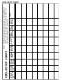
REEL MAKE,
MODEL &
HEIGHT OF
CUT
FRONT
TOOLING
MOUNT
TYPE
FRONT
TOOLING
MOUNT
POSITION
TOOLING SPIN DRIVE SPIN DRIVE
DISTANCE MOUNTING POSITION
SIDE R OR L
APART
REEL SETUP CHART
SPIN
SPEED
SETTING
SPIN
TRAVERSE
TORQUE SPEED
SETTING SETTING
NOTES
Note: These dimensions will vary due to reel position in
frame, reel dia., height of cut, roller position, etc.
Use these values as a guide only.
REEL SETUP CHART
28
THIS PAGE LEFT INTENTIONALLY BLANK FOR NOTE TAKING PORPOSES.
29
30
ASSEMBLY
AND
SERVICE
MANUAL
FOR SERIAL NUMBERS: 1XFRG55XPD0000025 AND UP
SPIN / RELIEF
REEL MOWER GRINDER
RG5500
(REV. 5-8-13)
1
DEALER PREPARATION/INSTALLATION CHECK LIST
IS LOCATED IN THE OPERATOR'S MANUAL
SEE OPERATOR'S MANUAL FOR INSTALLTION CHECKLIST
It is the responsibility of the dealer to complete the procedures listed in the Operators Manual then
review this checklist with the customer upon the delivery or the sale of this equipment.The installation
training goes over the basic operational functions of the equipment. To ensure adequate training, we
require that the following items are reviewed by your John Deere Dealer. Please check off to ensure
that you understand the following items before the installation training is complete:
Safety
IMPORTANT SAFETY MESSAGE FOR OWNERS/OPERATORS OF REEL GRINDERS
Safety is a primary concern in the design,
manufacture, sale, and use of reel grinders. As
a manufacturer of reel grinders, we want to confirm
to you, our customers, our concern for safety. We also
want to remind you about the simple, basic, and
common sense rules of safety when using a reel
grinder. Failure to follow these rules can result in
severe injury or death to operators or bystanders.
Before operating a reel grinder, an operator must
read and understand all of the information in the
operator’s manual and in the safety signs attached
to the product. A person who has not read or
understood the operator’s manual and safety signs
is not qualified to operate the unit. Accidents occur
often on machines that are used by someone who
has not read the operator’s manual and is not
familiar with the equipment. If you do not have an
operator’s manual or the current production safety
signs, contact the manufacturer or your dealer
immediately.
It is essential that everyone involved in the assembly,
operation, transport, maintenance, and storage of this
equipment be aware, concerned, prudent, and
properly trained in safety. Always use proper
shielding as specified by the manufacturer.
Reel grinders are designed for one-man operation.
Never operate the grinder with anyone near, or in
contact with, any part of the grinder. Be sure no one
else, including bystanders, are near you when you
operate this product.
Our current production machines include, as
standard equipment, guards or shields for the
grinding wheel, safety signs and an operator's
manual. Never bypass or operate the machine with
any of the guards or the safety devices removed.
Following these simple, basic safety rules, as well
as others identified in the owner’s manual and in the
product safety signs, will help minimize the
possibility of accidents and increase your
productivity in using this product. Be careful and
make sure that everyone who operates the grinder
knows and understands that this is a very powerful
piece of machinery, and if used improperly, serious
injury or death may result. The final responsibility for
safety rests with the operator of this machine.
Read and fully understand all the safety
practices discussed on pages 4 and 5 of this
manual. All safety rules must be understood
and followed by anyone who works with reel
grinders.
2
TO THE DEALER:
Assembly and proper installation of this product is the responsibility of the John Deere dealer. Read manual
instructions and safety rules. Make sure all items on the Preparation Check List in the Operator’s Manual are
completed before releasing equipment to the owner.
TO THE OWNER:
Read the Operator's Manual before operating your Frontier equipment. Keep this and all manuals handy for
ready reference. Require all operators to read the Operator's Manual carefully and become acquainted with
all adjustments and operating procedures before attempting to operate the equipment. Replacement
manuals can be obtained from your selling dealer.
The equipment you have purchased has been carefully engineered and manufactured to provide
dependable and satisfactory use. Like all mechanical products, it will require cleaning and upkeep. Lubricate
the unit as specified. Please observe all safety information in the Operator's Manual and safety decals on
the equipment.
For service, your authorized John Deere dealer has trained mechanics, genuine Frontier service parts, and
the necessary tools and equipment to handle all of your service needs.
Use only genuine Frontier service parts.
3
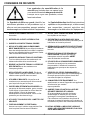
SAFETY INSTRUCTIONS
Safety Awareness Symbols are inserted
into this manual to alert you to possible
Safety Hazards. Whenever you see these
symbols, follow their instructions.
The Warning Symbol identifies
special instructions or procedures
which, if not correctly followed, could
result in personal injury.
!
The Caution Symbol identifies special
instructions or procedures which, if not
strictly observed, could result in damage to
or destruction of equipment.
1. KEEP GUARDS IN PLACE and in working
order.
12. DON'T OVERREACH. Keep proper footing and
balance at all times.
2. REMOVE WRENCHES AND OTHER
TOOLS.
13. MAINTAIN GRINDER WITH CARE. Follow
instructions in Service Manual for lubrication and
preventive maintenance.
3. KEEP WORK AREA CLEAN.
14. DISCONNECT POWER BEFORE SERVICING,
or when changing the grinding wheel.
4. DON'T USE IN DANGEROUS ENVIRONMENT.
Don't use Grinder in damp or wet locations.
15. REDUCE THE RISK OF UNINTENTIONAL
Machine is for indoor use only. Keep work area
STARTING. Make sure all switches are OFF
well lit.
before plugging in the grinder.
5. KEEP ALL VISITORS AWAY. All visitors
16. USE RECOMMENDED ACCESSORIES.
should be kept a safe distance from work area.
Consult the manual for recommended
accessories. Using improper accessories may
6. MAKE WORK AREA CHILD-PROOF with
cause risk of personal injury.
padlocks or master switches.
7. DON'T FORCE THE GRINDER. It will do the job 17. CHECK DAMAGED PARTS. A guard or other
part that is damaged or will not perform its
better and safer if used as specified in this
intended function should be properly repaired or
manual.
replaced.
8. USE THE RIGHT TOOL. Don't force the grinder
or an attachment to do a job for which it was not 18. KNOW YOUR EQUIPMENT. Read this manual
carefully. Learn its application and limitations as
designed.
well as specific potential hazards.
9. WEAR PROPER APPAREL. Wear no loose
clothing, gloves, neckties, or jewelry which may 19. KEEP ALL SAFETY DECALS CLEAN AND
LEGIBLE. If safety decals become damaged or
get caught in moving parts. Nonslip footwear is
illegible for any reason, replace immediately.
recommended. Wear protective hair covering to
Refer to replacement parts illustrations in Service
contain long hair.
Manual for the proper location and part numbers
of safety decals.
10. ALWAYS USE SAFETY GLASSES.
20. DO NOT OPERATE THE GRINDER WHEN
UNDER THE INFLUENCE OF DRUGS,
ALCOHOL, OR MEDICATION.
11. SECURE YOUR WORK. Make certain that the
cutting unit is securely fastened with the clamps
provided before operating.
4
SAFETY INSTRUCTIONS
IMPROPER USE OF GRINDING WHEEL MAY CAUSE
BREAKAGE AND SERIOUS INJURY.
!
Grinding is a safe operation if the few basic rules listed below are followed. These rules are based on material
contained in the ANSI B7.1 Safety Code for "Use, Care and Protection of Abrasive Wheels". For your safety,
we suggest you benefit from the experience of others and follow these rules.
DON'T
DO
1. DO always HANDLE AND STORE
wheels in a careful manner.
1. DON'T use a whee that is cracked, HAS BEEN
DROPPED, or one that is damaged.
2. DO VISUALLY INSPECT all wheels before
mounting for possible damage.
2. DON'T FORCE a wheel onto the machine OR
ALTER the size of the mounting hole--if wheel won't
fit the machine, get one that will.
3. DO CHECK MACHINE SPEED against the
established maximum safe operating speed
marked on wheel.
3. DON'T ever EXCEED MAXIMUM OPERATING
SPEED established for the wheel.
4. DON'T use mounting flanges on which the bearing
surfaces ARE NOT CLEAN, FLAT AND FREE OF
BURRS.
4. DO CHECK MOUNTING FLANGES for equal
and correct diameter.
5. DO USE MOUNTING BLOTTERS when
supplied with wheels.
5. DON'T TIGHTEN the mounting nut EXCESSIVELY.
6. DO be sure WORK REST is properly
adjusted.
6. DON'T grind on the SIDE OF THE WHEEL (see
Safety Code B7.2 for exception).
7. DO always USE A SAFETY GUARD COVERING
at least one-half of the grinding wheel.
7. DON'T start the machine until the WHEEL GUARD
IS IN PLACE.
8. DO allow NEWLY MOUNTED WHEELS to run at
operating speed, with guard in place, for at least
one minute before grinding.
8. DON'T JAM work into the wheel.
9. DON'T STAND DIRECTLY IN FRONT of a
grinding wheel whenever a grinder is started.
9. DO always WEAR SAFETY GLASSES or some
type of eye protection when grinding.
10. DON'T FORCE GRINDING so that motor slows
noticeably or work gets hot.
AVOID INHALATION OF DUST generated by grinding and cutting operations. Exposure
to dust may cause respiratory ailments. Use approved NIOSH or MSHA respirators, safety
glasses or face shields, and protective clothing. Provide adequate ventilation to eliminate
dust, or to maintain dust level below the Threshold Limit Value for nuisance dust as
classified by OSHA.
5
TABLE OF CONTENTS
This machine is intended for grinding the reel of reel type mower units ONLY.
Any use other than this may cause personal injury and void the warranty.
To assure the quality and safety of your machine and to maintain the warranty,
you MUST use original equipment manufactur's replacement parts and have
any repair work done by a qualified professional.
ALL operators of this equipment must be thoroughly trained BEFORE operating
the equipment.
Do not use compressed air to clean grinding dust from the machine. This dust
can cause personal injury as well as damage to the grinder. Machine is for
indoor use only. Do not use a power washer to clean the machine.
Low Voltage Relay
The grinder is equipped with a high-low voltage relay
which is factory preset at 100-140 VAC. If the power
supply line does not deliver 100-140 VAC power under
load, the relay will open and trip out the starter. If this
occurs, your power supply line is incorrect and must be
corrected before proceeding further with the grinder.
TABLE OF CONTENTS
Safety Instructions .................................................................................................................
Daily Maintenance ..................................................................................................................
Service Data ..........................................................................................................................
Assembly Instructions ............................................................................................................
Maintenance ..........................................................................................................................
Adjustments ...........................................................................................................................
Electrical Troubleshooting ......................................................................................................
Mechanical Troubleshooting ..................................................................................................
Exploded Views and parts Lists .............................................................................................
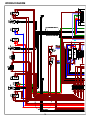
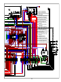
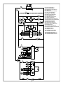
Wiring Diagram & Schematic ................................................................................................
Page 2-6
Page 6
Page 7
Page 8-12
Page 13-19
Page 20-25
Page 26-41
Page 42-43
Page 44-73
Page 74-76
DAILY MAINTENANCE BY THE OPERATOR
On a daily basis, clean the machine by wiping it off.
On a daily basis, remove all grinding grit from the grinding shaft, traverse shafts, and tooling
bar area.
On a daily basis, inspect the machine for loose fasteners or components.
Contact your company's Maintenance Department if damaged or defective parts are found.
DO NOT USE COMPRESSED AIR TO CLEAN
GRINDING DUST FROM GRINDER
6
SERVICE DATA
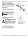
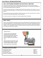
SKILL AND TRAINING REQUIRED FOR SERVICING
This Service Manual is designed for technicians who have the necessary mechanical and electrical
knowledge and skills to reliably test and repair the RG5500 Spin/Relief Grinder. For those without this
background, service can be arranged through your local dealer.
This section presumes that you are already familiar with the normal operation of the grinder. If not, you should
read the operators manual, or do the servicing in conjunction with someone who is familiar with its operation.
Persons without the necessary knowledge and skills should not remove any panels, shields or attempt any
internal troubleshooting, adjustments, or parts replacement.
If you have questions not answered in this manual, please contact your dealer.
TORQUE REQUIREMENTS
Throughout this manual we refer to torque
requirements as "firmly tighten" or the like. For more
specific torque values, refer to the information
below.
GRADE 2
Bolts Going Into a Nut, or Into a Thread Hole in
Steel.
Refer to the table at the right.
Bolts Going Into a Thread Hole In Aluminum
Use the Grade 2 values in the table at the right.
SMOOTH
HEAD
3 MARKS
on HEAD
1/4 In.
thread
6 ft-lbs
(0.8 kg-m)
9 ft-lbs
(1.25 kg-m)
13 ft-lbs
(1.8 kg-m)
5/16 In.
thread
11 ft-lbs
(1.5 kg-m)
18 ft-lbs
(2.5 kg-m)
28 ft-lbs
(3.9 kg-m)
31 ft-lbs
(4.3 kg-m)
46 ft-lbs
(6.4 kg-m)
75 ft-lbs
(10.4 kg-m)
3/8 In.
thread
Socket-Head Screws Going Into a Nut or Steel
Use the Grade 8 values in the table at the right.
Machine Screws
No. 6 screws: 11 in.- lbs (0.125kg - m)
No. 8 screws: 20 in. - lbs (0.23 kg - m)
No. 10 screws: 32 in. - lbs (0.37 kg - m)
7
GRADE 5 GRADE 8
19 ft-lbs
(2.6 kg-m)
6 MARKS
on HEAD
7/16 In.
thread
30 ft-lbs
(4.1 kg-m)
50 ft-lbs
(6.9 kg-m)
1/2 In.
thread
45 ft-lbs
(6.2 kg-m)
75 ft-lbs
115 ft-lbs
(10.4 kg-m) (15.9 kg-m)
ASSEMBLY INSTRUCTIONS
Remove the sides, front, and back of the crate.
Remove the plastic bag, shrink wrap and bubble
wrap. Remove the metal clips that secure the
grinder to the crate base. With a fork lift, raise the
grinder from the wood base and set it in its final
position. See FIG. 1 and 2.
41" [104cm]
R36"
[914cm]
OPTIONAL
PLATFORM
LIFT SYS.
83" [211cm]
THE UNIT WEIGHS OPTIONAL
BOOM
1200 LBS. [544 kg].
TO LIFT, USE POWER
EQUIPMENT.
45"
[115cm]
Remove shipping straps and window protective
sheets.
71"
[181cm]
FIG. 1
POSITION BASE
The RG5500 Spin/Relief Grinder will require an operating area of about 119" W x 127" D x 90" H
(302 cm x 323cm x 229 cm). The machine operator will operate the unit from the front of the machine.
Position the base to allow sufficient operating room in front and to the rear of the machine. See FIG. 1
and 2.
The base should be placed on a relatively level concrete floor, with ample ceiling height to allow for the
installation of the unit. Do not place the unit across two concrete slab seams or across a large crack.
71"
[181cm]
83"
[211cm]
Optional
Boom Kit
88
[224cm]
70"
[178cm]
41"23
[104cm]
FIG.
OPTIONAL
PLATFORM LIFT
FIG. 2
45"
[115cm]
8
ASSEMBLY INSTRUCTIONS (Continued)
Remove the carton and remove the contents from the carton
onto a workbench. The carton includes:
Alignment Gage
Multi position Brackets
Diamond Dresser
Raised Rear
Support
Drive Coupler
Spanner Wrench
Product Packet Assembly
(Operators & Service Manuals)
9
ASSEMBLY INSTRUCTIONS (Continued)
LEVEL BASE
Place a level on the top of the table and check the
unit for level side to side. Adjust the leveling feet as
necessary until the machine is level.
See FIG. 3 and 4.
Place a level across the table from front to rear.
Adjust the leveling feet as necessary until the
machine is level. See FIG. 3 and 5.
LOOSEN JAM NUT TO
ADJUST FOOT
LEVELING FEET LOCATED
AT CORNERS OF MAHCINE
When both front to back and side to side leveling
procedures have been completed, thread the hex
jam nuts up against the nut that is welded to the
bottom of the machine. Be careful not to move the
leveling feet during when tightening the jam nut. See
FIG. 3. Make certain that all four leveling feet are
firmly contacting the floor.
FIG. 3
Recheck that the machine is level after locking the
four feet into position.
FIG. 4
FIG. 5
10
ASSEMBLY INSTRUCTIONS (Continued)
IMPORTANT GROUNDING INSTRUCTIONS
In case of a malfunction or breakdown, grounding reduces the risk of electrical shock by providing a path
of least resistance for electrical current.
This Grinder has an electrical cord with an equipment grounding conductor and a grounding plug. The
plug must be plugged into a matching outlet that is properly installed and grounded according to all local
or other appropriate electrical codes and ordinances.
Before plugging in the Grinder, make sure it will be connected to a supply circuit protected by a properly
sized circuit breaker or fuse. SEE SERIAL NUMBER PLATE FOR FULL LOAD AMP RATING OF YOUR
MACHINE.
Never modify the plug provided with the machine--if it won't fit the outlet, have a proper outlet and circuit
installed by a qualified electrician.
ALWAYS PROVIDE A PROPER ELECTRICAL GROUND FOR YOUR MACHINE.
AN IMPROPER CONNECTION CAN CAUSE A DANGEROUS ELECTRICAL
SHOCK. IF YOU ARE UNSURE OF THE PROPER ELECTRICAL GROUNDING
PROCEDURE, CONTACT A QUALIFIED ELECTRICIAN.
11
ASSEMBLY INSTRUCTIONS (Continued)
APPLY POWER
BEFORE YOU APPLY POWER TO THE GRINDER,
REFER TO THE "IMPORTANT GROUNDING
INSTRUCTIONS" ON PREVIOUS PAGE.
FIG. 6
Plug the control box power cord into a standard 115V AC 20-amp
grounded receptacle. See FIG. 6.
IT IS RECOMMENDED THAT THIS SPIN/RELIEF
GRINDER HAS ITS OWN PERMANENT POWER
CONNECTION FROM THE POWER DISTRIBUTION
PANEL, WITH NO OTHER MAJOR POWER DRAW
EQUIPMENT ON THE SAME LINE.
IT IS REQUIRED THAT THE POWER DELIVERED TO
THIS GRINDER IS 115 VAC - 20 AMPS. THE
TOLERANCE ON THIS POWER REQUIREMENT IS +/5%. THEREFORE THE MINIMUM VOLTAGE REQUIREMENT IS 109VAC WITH 20 AMPS. VOLTAGE MUST BE
CHECKED WITH ALL EQUIPMENT UNDER LOAD
(OPERATING) ON THE CIRCUIT.
The grinder is equipped with a highlow voltage relay which is factory
preset at 100-140 VAC. If the power
supply line does not deliver 100-140
VAC power under load, the relay will
open and trip out the starter. If this
occurs, your power supply line is
incorrect and must be correct before
proceeding further with the grinder.
DO NOT OPERATE THIS GRINDER WITH AN
EXTENSION CORD.
DO NOT OPERATE THIS GRINDER ON A GROUND FAULT
A PROPER GROUND IS REQUIRED FOR SAFE
OPERATION OF THE EQUIPMENT. VERIFY THAT THE
RECEPTACLE GROUND IS A PROPER GROUND
BEFORE PLUGGING IN THE MACHINE.
IMPROPER GROUNDING IN YOUR BUILDING MAY
RESULT IN A DANGEROUS SHOCK TO THE OPERATOR
OR CAUSE THE GRINDER TO MALFUNCTION.
When installing the grinder, the following guidelines should be used
to establish the wire size between the power panel in your building
and the grinder receptacle. Note that the wiring in your building
must be per code between main power panels and sub panels.
FOR 20 AMP RATED LARGE MACHINES
For 0 to 40 Feet (0 to 12 M) from panel to receptacle = Use 12 Ga. (4.0 mm) Wire.
For 40 to 60 Feet (12 to 18 M) from panel to receptacle = Use 10 Ga. (6.0 mm) Wire.
For 60 to 100 Feet (18 to 30 M) from panel to receptacle = Use 8 Ga. (10.0 mm) Wire.
For 100 to 160 Feet (30 to 48 M) from panel to receptacle = Use 6 Ga. (16.0 mm) Wire.
12
PERIODIC MAINTENANCE
DAILY MAINTENANCE IS SPECIFIED ON PAGE 6,
AND IS TO BE PERFORMED BY THE OPERATOR.
LISTED BELOW ARE PERIODIC MAINTENANCE
ITEMS TO BE PERFORMED BY YOUR
COMPANY'S MAINTENANCE DEPARTMENT:
1. Clean the dust tray located at the lower front
of the machine monthly using a vacuum or
by removing it. Pull the tray out until the back
of the tray is even with the front of the frame
and vacuum it out. To remove continue to
pull straight out until the tray is free.
USE CAUTION WHEN PULLING THE
TRAY OUT AS THERE IS NO
MECHANICAL STOP. WHEN REMOVING
TRAY PULL STRAIGHT OUT AND
SUPPORT THE TRAY TO PREVENT
DUMPING.
2. Inspect the Poly-V belt on the grinding motor
for cracking and make any
necessary adjustments every three months.
3. Wipe off and lubricate with never-seize, the
horizontal adjustment shafts located on the
tooling every six months.
DUST TRAY
VERTICAL ADJUSTMENT
SHAFTS LOCATED INSIDE
HOUSING - ACCESS THRU
SIDE PANELS
FIG. 7
POLY-V BELT LOCATED
BEHIND PANEL
4. Wipe off and lubricate with never-seize, the
vertical adjustment shafts every six months.
Run the arms up and down to coat the
working areas of the shaft.
HORIZONTAL
ADJUSTMENT
SHAFT
5. Inspect the traverse cog belt for
cracking and defects every three months.
Remove any grit or dust that may affect the
function of the belt. Adjust tension if
necessary per procedures called out in the
adjustment section. See FIG 9.
6. Clean and lubricate the grinding shaft and
traverse shafts every 2 to 4 weeks. Follow
the proceedure on the next page.
FIG. 8
7. Lubricate grinding shaft bearings with one
shot of grease once every 2 years. See
FIG 9.
DO NOT GREASE GRINDING SHAFT
BEARINGS FOR THE FIRST 2 YEARS. THEY
ARE GREASED AT THE FACTORY. GREASING
MAY CAUSE THE BEARINGS TO OVERHEAT
AND FAIL PREMATURELY.
13
LUBRICATION
LUBRICATION OF GRINDING SHAFT AND LINEAR BEARINGS
STEP 1 – Thoroughly clean all three shafts.
STEP 2 – Flood spray all three shafts with CRC 3-36 until the lubricant is dripping off the shafts. (Do
not use a Teflon-based lubricant) Then run the grinding head assemblies back and forth through
their full range of travel. This will remove the dust and deposits from inside the wheel flanges. Repeat
if necessary until lubrication is clear of deposits. Clean keyways located on the grinding shaft with soft
brush.
STEP 3 – With a clean rag, wipe off the excess amount of lubricant from the shafts. Run the grinding
assemblies through their range of travel and wipe the shafts after each traverse. Repeat until the
shafts are dry to the feel. This completes the lubrication process.
IMPORTANT:
If the unit will be shut down for an extended period of time, more than four weeks, then the shafts and
other appropriate parts of the unit should be flooded with lubricant and that lubricant left in place until
the unit is brought back into service. When the unit is brought back into service the full lubrication
procedure as stated above should be repeated.
GRINDING SHAFT
BEARING
GRINDING SHAFT
GRINDING SHAFT
BEARING
COG BELT
POLY-V BELT
TRAVERSE SHAFTS
FIG. 9
14
MAINTENANCE
REPLACEMENT OF GRINDING WHEEL
To replace the wheel first remove the left side cover
panel. Now, lower the left side of the grinding shaft and
raise the right side. Next, loosen the two bolts that hold
the bearing bracket on the relief hub so that that
bearings pivot away from the wheel and hub (toward
the front of the machine). See FIG 11. Press the index
finger down and the wheel and hub assembly should
move freely to the right.
Then remove the left side bearing. First loosen the
setscrews on the bearing collar then remove the four
screws that hold the bearing to the left arm.
BEARING
RELIEF FLANGE
RELIEF WHEEL
RELIEF NUT
SPIN NUT
SPIN WHEEL
SPIN FLANGE
Slide the grinding wheel hub assembly(s) off the shaft
taking note of what side the nut is on. Use the spanner
wrench to remove and replace the grinding wheel(s).
NOTE: THE RELIEF HUB HAS A LEFT
HAND THREAD FOR THE NUT. THE SPIN
HUB HAS A RIGHT HAND THREAD.
FIG. 10
Place the grinding wheel hub assembly(s) back on the
grinding shaft. Verify that the spin hub is located
between the spin drive yoke assembly and the relief
hub is to the right of the relief drive assembly before
lowering the grinding shaft.
MAKE SURE THE WHEEL(S) IS PLACED ON
THE SHAFT WITH THE SAME ORIENTATION
AS SHOWN. FAILURE TO INSTALL
CORRECTLY WILL CAUSE THE WHEEL NUT
TO LOOSEN. (THE NUT ON THE RELIEF
HUB SHOULD BE TO THE RIGHT & THE
NUT ON THE SPIN HUB SHOULD BE TO
THE LEFT.)
Reinstall the bearing on the left side of the grinding
shaft making sure to fit the pilot on the bearing into
arm. Tighten the four mounting screws, and then
tighten the setscrews to the shaft. Reinstall the left
side cover panel. Move bearing support bracket back
into place. See relief hub bearing adjustment to set the
bracket correctly.
15
Loosen bolts and tip bracket
back. Press in the indexing
finger and the wheel should
slide freely to the right.
FIG. 11
MAINTENANCE (Continued)
GRINDING MOTOR BELT REPLACEMENT/
ALIGNMENT
To replace or inspect the grinding motor belt,
remove the right side cover panel. To remove the
belt, pull down on the tensioner pulley.
For the belt to function properly the grinding shaft
pulley and the grinding motor pulley must be in line
with the tensioner pulley. To adjust the pulley
position loosen the setscrews on the pulley.
Locate the belt in the center of the idler pulley.
Measure from the arm to the edge of the belt at the
idler pulley. Adjust the two other pulley's until the
same measurement is achieved and tighten the
pulley setscrews.
Reinstall the right side cover panel, then run the
grind motor to assure that the belt is not misaligned.
The belt will walk off the pulley if the system is not
aligned properly.
FIG. 12
TRAVERSE BELT REPLACEMENT
To replace the traverse belt, remove the left side
cover panel, then loosen the nuts on the left side
pulley that are used to tension the belt. Remove the
right side cover panel. Loosen the screws holding
the traverse motor and tilt the bottom of the motor
out releasing any remaining tension on the belt. On
the left side remove the nut from the bottom belt
tensioning screw, this will allow the belt to be
removed.
Place a new belt on the left pulley making sure it is
seated properly in the cogged teeth and replace the
locknut. Feed the new belt throught the slot on the
right arm and place on motor pulley. Use the motor
as a lever to apply tension to the new belt. Tighten
motor screws and adjust the tension in the belt as
specified in the BELT TENSION section. Adjust the
height of the motor pulley if necessary so the belt is
located in the center of the traverse belt clamp.
FIG. 13
Reinstall the left side and right side cover panels,
then test the traverse motor.
16
MAINTENANCE (Continued)
TRAVERSE SHAFT/LINEAR BEARING
REPLACEMENT
2. REMOVE REAR PIVOT BOLT
To replace the traverse shafts or the linear bearings in
the Spin or Relief assembly, first remove the left side
cover panel.
1. REMOVE GRINDING
SHAFT AND
TRAVERSE BELT
REMOVE GRINDING SHAFT:
Next you will need to remove the grinding shaft. First
move the relief hub away from the relief hub
assemlby (see Replacement of Griniding wheel
section for details). Then remove the grinding motor
belt and pulley (see Grinding Motor Belt
Replacement). Now loosen the setscrews on the
right side bearing to allow the grinding shaft to slide
out of the bearing. Next remove the left side grinding
shaft bearing. The grinding shaft is heavy so take
appropriate measures when lifting or removing. To
remove the grinding shaft lift up on the left end and
slide the shaft out of the right side bearing. Set the
shaft on the floor or bench out of the way.
THE GRINDING SHAFT WEIGHS 75LBS
[34 Kg] USE APPROPRIATE LIFTING
3. LIFT ARM OFF REAR
DEVICES TO AVOID INJURY.
PIVOT SHAFT AND SLIDE
ARM BACK THEN OUT.
REMOVE THE TRAVERSE BELT:
(See Traverse Belt Replacement section)
REMOVING THE TRAVERSE SHAFTS:
To remove the traverse shafts use the vertical
adjusters to lower both grinding shaft support arms
until they are in there lowest position. Now remove
the left grindng shaft support arm. To remove the left
arm, first remove the bolt at the rear of the machine.
(It may be necessary to clamp onto the shaft that the
bolt is screwed into so that it does not spin.) After
removing the bolt, pull the arm off the rear shaft. Now
move the arm toward the rear of the machine to
disengage the front of the arm from the vertical
adjuster. Next pull the arm away from the grinder
and off the traverse shafts. (Note, the shafts may
come out of the right side arm so support the shafts.)
Fig. 14
TO REASSEMBLE:
Clean the 2 spherical bearings in the right arm
and place the traverse shaft into the bearings.
(The shafts should slide into the bearings.
There is very minimal clearance so the shafts
need to be preciesly aligned for the shafts to
slide into the bearings.) Next slide the grinding
head assemblies (spin first then relief) onto the
traverse shafts. Now, clean the bearing in the
left arm. Then align the bearings in the left arm
to the two traverse shafts. The shafts should
slide into the bearings. Reinstall the left arm
into the vertical adjuster housing and onto the
rear support shaft. Reinstall the rear pivot bolt
and tighten. Continue to install the traverse
belt, grinding shaft, and grinding motor belt.
See the sections on Traverse Belt Replacement, Replacement of Grinding Wheel, Grinding Motor Belt Replacement, Traverse Belt
Tension, and Relief Grinding Head Bearing
Adjustments for addtional details.
Slide the Spin and Relief Grinding Head Assemblies
off the traverse shafts.
Replace the shafts if necessary.
REPLACING THE TRAVERSE BEARING:
To replace the traverse bearings, press the bearings
out of the bearing housing. Slide in the new bearings
and secure in place with the seals. (Two bearings go
in the front and 1 bearing the rear of the housing).
17
MAINTENANCE (Continued)
CLEANING AND MAINTENANCE GUIDELINES FOR POLYCARBONATE
WINDOWS
Cleaning Instructions
DO NOT USE GASOLINE
Adherence to regular and proper
cleaning procedures is recommended
to preserve appearance and performance.
Washing to Minimize Scratching
Wash polycarbonate windows with a mild dish washing liquid detergent and lukewarm water, using a clean
soft sponge or a soft cloth. Rinse well with clean water. Dry thoroughly with a moist cellulose sponge to
prevent water spots. Do not scrub or use brushes on these windows. Also, do not use butyl cellosolve in
direct sunlight.
Fresh paint splashes and grease can be removed easily before drying by rubbing lightly with a good
grade of VM&P naphtha or isopropyl alcohol. Afterward, a warm final wash should be made, using a mild
dish washing liquid detergent solution and ending with a thorough rinsing with clean water.
Minimizing Hairline Scratches
Scratches and minor abrasions can be minimized by using a mild automobile polish. Three such
products that tend to polish and fill scratches are Johnson paste Wax, Novus Plastic Polish #1 and #2,
and Mirror Glaze plastic polish (M.G. M10). It is suggested that a test be made on a corner of the
polycarbonate window with the product selected following the polish manufacturer's instructions.
Some Important "DON'TS"
DO NOT use abrasive or highly alkaline cleaners on the polycarbonate windows.
Never scrape polycarbonate windows with squeegees, razor blades or other sharp
instruments.
Benzene, gasoline, acetone or carbon tetrachloride should NEVER be used on polycarbonate
windows.
DO NOT clean polycarbonate windows in hot sun or at elevated temperatures.
Graffiti Removal
• Butyl cellosolve, (for removal of paints, marking pen inks, lipstick, etc.)
• The use of masking tape, adhesive tape or lint removal tools works well for lifting off old
weathered paints.
• To remove labels, stickers, etc., the use of kerosene, VM&P naphtha or petroleum spirits is
generally effective. When the solvent will not penetrate stickier material, apply heat (hair
dryer) to soften the adhesive and promote removal.
GASOLINE SHOULD NOT BE USED!
18
MAINTENANCE (Continued)
DIGITAL GAGE
Important
Do not mark the scale unit with an electric engraver or scratch
the scale.
Always use an SR44 battery (silver oxide cell)
If the scale will not be used for more than three months, remove
the battery and store it properly. Otherwise, leakage, if any, from
the battery may damage the unit.
Description of Parts
1. Beam
3. Battery compartment
5. Display
7. ZERO/ABS switch
9. Inch/mm Switch
11. Slider
2. Main Scale
4. Outp Connection
6. ON/OFF Power
8. Origin Switch
10. Tapped hole
Battery Installation and Origin Setting
Set the origin of the scale after installing the battery. Otherwise,
the error sign("E" at the least significant digit) may appear,
resulting in incorrect measurements.
1)
To install the battery, remove the compartment lid and
install the SR44 battery with its positive side facing up. After
the battery is installed, set the origin.
2)
To set the origin, move the slider to an area you wish to set
as your origin. Turn the power on. Hold the ORIGIN switch
down for more than one second. The "0.00" display
appears, indication Origin setting is complete. The origin
will be retained even if the power is turned off.
Incremental (INC) & Absolute (ABS) mode
The LCD will dispay measurements from the origin when turned on
(ABS mode). To set the origin see above. The display can be set
to zero at any desired position by pressing the ZERO/ABS switch.
INC indicator will apper in the display (INC mode), permitting
measurements from this zero point. To return to the ABS mode
hold the ZERO/ABS button form more than 2 seconds.
Error Symptoms & Remedies
ERRC and display flickering: Occurs when the scale
surface is stained. Clean the scale surface and coat a thin
film of low viscosity oil to keep out moisture.
E in the least significant digit: This occurs when the
slider is moved too quickly, but it does not affect the
measurement. If it stays on when the slider stops, the scale
surface is probably stained. If this is the case, take
remedies as for ERRC.
B indication: Battery voltage is low. Replace the
battery as soon as possible.
Cleaning
Clean gage with CRC 3-36 Cleaning and Lubrication OIl. Wipe off
excess after cleaning. If CRC 3-36 is not available, use Denatured
Alcohol to clean, then apply light oil and wipe off excess.
19
ADJUSTMENTS
PROXIMITY SWITCH
For the proximity switch to perform properly and
reverse the direction of the grinding head assembly,
the sensor end of the proximity switch must face
toward the head assembly that is in use and must
be mounted such that it is located past the edge of
the prox holder.
NOTE: The light on the proximity switch activates
when metal is approximately 3/16" [4.6 mm] from the
front of the proximity switch.
FIG. 15
VERTICAL INFEED SHAFT DRAG
If the grinding shaft tends to walk during grinding,
the drag on the vertical adjusters needs to be
increased. To increase the drag in the vertical
adjustment shafts, tighten the setscrew on the
back of the vertical adjustment housing.
VERTICAL INFEED SHAFT
DRAG SETSCREW LOCATED
ON BACK OF EACH TOWER.
FIG. 16
20
ADJUSTMENTS (Continued)
TRAVERSE BELT TENSION
To adjust the tension on the traverse belt, tighten
the screws and nuts located to the left side of the
traverse belt behind the left side cover panel to a
minimum of 1.75" [44 mm]. The traverse belt
should be level when adjusting the belt tension.
DO NOT OVERTIGHTEN.
OVERTIGHTENING COULD
DAMAGE THE BELT OR
TRAVERSE DRIVE SYSTEM.
FIG. 17
TRAVERSE CLAMP FORCE
If the traverse clamp is slipping during regular
operation it may become necessary to adjust the
clamp tip location. To adjust the clamp tip, loosen
the jam nut and rotate the clamp tip. The clamp tip
should be adjusted to the dimension specified in
FIG 18. To measure, move the traverse belt out of
the way. Measure the clamped distance from the
clamp tip to the clamping block (shoe). To secure
the new position, jam the nut against the clamp
being careful not to move the clamp tip.
If there is not enough adjustment in the clamp tip,
the bracket that supports the clamp can also be
adjusted. The bracket is slotted, to adjust loosen
the two screws that are hold the bracket in place
and slide the bracket forward or back. Then
retighten the screws, make sure they are tight or the
bracket will move during clamping. Check the tip
distance and make any necessary adjustments.
.10" [2.5 mm]
FIG. 18
THE TIP HAS BEEN FACTORY SET SO THAT
IT WILL SLIP IF THE GRINDING HEAD
ASSEMBLY COMES IN CONTACT WITH
SOMETHING. CAUTION SHOULD BE USED
AS ADJUSTING THE TIP WILL AFFECT THE
SLIP LOAD AND COULD DAMAGE THE
CLAMP TIP, BELT OR TRAVERSE DRIVE
SYSTEM.
21
ADJUSTMENTS (Continued)
SPIN GRINDING HEAD WEAR PADS
The bronze wear pads used to move the spin wheel
will wear and may need to be adjusted or replaced.
When pad wears to within a 1/16" [1.5 mm] of the
screws, the pad will need to be flipped or replaced.
The holes in the pads are offset slightly, this allows the
pads to be flipped if neccessary to accomplish the best
fit. When installing new pads, flip or rotate the pads
until Gap 2 is as small as possible without the pads
pinching the wheel.
On the spin grinding head assembly, the distance from
the pad to the wheel can be adjusted in and out by
loosening the screws located on the sides of the
yokes. Gap 1 should be adjusted to about 1/16"
[1.5 mm]. See FIG. 19
FIG. 19
6MM [.25"] MAXIMUM
DISTANCE
SAFETY SWITCH ALIGNMENT/REPLACEMENT
The safety switch located on the front and rear guard
door must line up properly or the grinder will not
function.
The front and rear door switches must be within 6mm
[.25"] and the targets on the switches must line up in
order for the switch to function properly. See FIG. 20
and 21.
FRONT DOOR SWITCH
(INSIDE UPPER RIGHT SIDE)
The switches are attached to the guarding using a
"Torx" style tamper resistant screws. A tool for this
type of screw is required to make this adjustment.
FIG. 20
6MM [.25"] MAXIMUM
DISTANCE
REAR DOOR SIWTCH
FIG. 21
22
ADJUSTMENTS (Continued)
RELIEF GRINDING HEAD BEARING ADJUSTMENTS
It may be necessary to adjust the guide bearings on the relief
head. To adjust the position of the support bearings,
POSITION THE GRINDING HEAD AT THE FAR LEFT
POSITION, loosen the two positioning bolts located on the
side of the support assembly. Press on the support assembly
until the top support bearing is touching the grinding wheel
hub. Hold the support in place with the bearing touching the
hub and tighten the two positioning bolts. Check to see that
the bearing is touching or has minimal clearance to the hub
through the full range of left to right travel.
Top Support Bearing
Assembly
NOTE: EXCESSIVE PRELOAD OF THE
BEAR ING ASSEMBLIES ON THE HUB CAN
CAUSE THE BEARINGS TO WEAR QUICKER
AND COULD CAUSE THEM TO FAIL
PREMATURELY.
Bracket
Positioning
Bolts
23
FIG. 22
CONTROL BOARD POTENTIOMETER ADJUSTMENTS
POTENTIOMETER ADJUSTMENTS TRAVERSE DRIVE CONTROL (TDC)
Min. Speed--Factory set at full (CCW) 8:30. Do not change this setting.
(Right Traverse) Forward Torque--Factory set at full (CW) 4:30. Do not change this setting.
(Left Traverse) Reverse Torque--Factory set at full (CW) 4:30. Do not change this setting.
IR COMP--Factory set to 9:00. IR COMP is current (I) resistance (R) compensation (COMP). IR COMP adjusts the
output voltage of the drive which balances load to motor RPM. Regulation of a traverse motor may be improved by
slight adjustment of the IR COMP pot clockwise from its factory-set position. Overcompensation causes the motor
to oscillate or to increase speed when fully loaded. If you reach such a point, turn the IR COMP pot
counterclockwise until the symptoms disappear.
Max. Speed--Set at 3:30 for maximum voltage of 90 Volts DC to the traverse motor. When voltage is above 90 volts
DC, the traverse motor will start to pulsate and not run smoothly.
(Right Traverse) Forward Acceleration--Factory set at full (CCW) 8:30. Do not change this setting.
(Left Traverse) Reverse Acceleration--Factory set at full (CCW) 8:30. Do not change this setting.
(DB) Dead Band is the potentiometer setting for the 50 or 60 Hz cycle control. Factory set to 9:00, works for both
50 and 60 Hz. Do not change this setting.
Calibrating the DWELL TIME rotary DIP switch adjusts the amount of time the process remains in the stop position
after a limit switch is actuated. The DWELL TIME range is adjustable from 0-4 seconds. A DIP switch setting of 0
sets the DWELL TIME to 0 seconds, while a setting of 9 sets the DWELL TIME to 4.5 seconds. Dwell time is preset
to #4 setting for a 2 second dwell time when reversing at each end of stroke. A setting of 6, sets the dwell time at
3 seconds, etc.
Diagnostic LED's indicate the function that is currently being performed:
POWER indicates that AC power is being applied to the control.
FORWARD indicates that the process is running in the forward direction
(traversing left).
REVERSE indicates that the process is running in the reverse direction
(traversing right).
PROX 1 FWD LIMIT lights when the forward limit switch is actuated (left prox.).
PROX 2 REV LIMIT lights when the reverse limit switch is actuated (right prox.).
DWELL lights when the process remains stopped after a proximity switch is
actuated.
Potentiometer
Clock Orientation
FIG. 23
24
CONTROL BOARD POTENTIOMETER ADJUSTMENTS (Continued)
SPIN DRIVE CONTROL BOARD (SDC)
The Spin Drive Control Board has four potentiometers, two switches and one dial as shown on FIG. 24. These
potentiometers,swtiches and dial have been set at the factory to the positions shown on FIG. 24.
In the Relief Grinding Mode-The Torque Shut Off mode selector allows you to turn on or off the Torque Shut Off feature. When switch 1 is set to ON, the
board will decrease the spin motor torque once the shut time is achieved after leaving the right proximity sensor. The amount
of time it takes before the torque is decreased is set with the Torque Shut Off Delay dial. The spin motor toque will be
increased to the higher value once the right proximity switch is activated again. If the Torque Shut Off selector is in the OFF
position the torque will remain constant during relief grinding. This should be set to OFF.
Torque Shut Off Delay dail is used to set the duration of time before the torque is decreased after leaving the right proximity
sensor during relief grinding. If the dial is turned clockwise (higher number) the higher torque value will stay on for a longer
period of time.
The Relief Speed (RSP) and the Relief Torque Pot (RTP) interact with each other. The (RSP) is located on the spin board as a
remote speed preset at 12:00 (20 Volts DC). See FIG. 24. The (RTP) is located on the control panel and is for relief torque
adjustment.
Relief Speed Pot (SPEED) when rotated clockwise will increase spin drive speed (the speed at which the reel indexes to the
next blade). This speed should never be above the 3:00 setting.
Relief Torque Pot (TORQ) is used to vary the reel to finger holding torque for relief grinding. The
recommended starting point is 30 in/lbs of torque setting. Never adjust the (RTP) potentiometer dial past the red line marking.
Setting the reel to finger torque to high could cause the spin motor system to not operate smoothly.
Relief Idle Torque Pot (ITP) is used to vary the reel to finger holding torque once the shut time is achieved after leaving the right
proximity sensor if the Torque Shut Off Selector is set to on.
In the Spin Grinding Mode-The Spin Torque Potentiometer (STP) and the Spin Speed Pot (SSP) interact with each other. The (STP) is located on the spin
board as remote torque preset at 2:00 for torque setting. See FIG. 24. The (SSP) is located on the control panel and is for spin
speed adjustment.
Spin Torque Pot (STP) controls maximum torque allowable in the spin grinding cycle only. This should never be adjusted past
the 3:00 position. If the reel does not turn check that the reel is free turning by hand spinning with the power off and the spin
drive disconnected.
The Spin speed Pot (SSP) controls reel spin speed, adjust as required. This controls the spin drive speed for spinning the reel.
IR COMP Pot-The IR Compensation is factory set at 9:00.
Regulation of the spin or relief grind spin motor may be improved by a slight adjustment of the IR COMP pot clockwise from its
factory-set position. Overcompensation causes the motor to oscillate or to increase speed when fully loaded. If you reach such
a point, turn the IR COMP pot counterclockwise until symptoms just disappear.
DELAY SET
TO 1
RELIEF SPEED
POT (SPEED) 12:00
SPIN TORQUE POT
(TORQ) 2:00
SWITCH 1
SET TO OFF
IR COMP
POT
9:00
IDLE TORQUE
POT (ITP)
10:00
25
Potentiometer Clock
Orientation
FIG. 24
ELECTRICAL TROUBLESHOOTING
SKILL AND TRAINING REQUIRED FOR ELECTRICAL SERVICING
This Electrical Troubleshooting section is designed for technicians who have the necessary electrical
knowledge and skills to reliably test and repair the RG5500 electrical system. For those without that background,
service can be arranged through your local dealer.
This section presumes that you are already familiar with the normal operation of the Grinder. If not, you
should read the Operator's Manual, or do the servicing in conjunction with someone who is familiar with its
operation.
Persons without the necessary knowledge and skills should not remove the control panel cover or attempt
any internal troubleshooting, adjustments, or parts replacement.
If you have any question not answered in this manual, please call your local dealer.
WIRE LABELS
All wires on the RG5500 have a wire label at each end for troubleshooting. The wire label has a code which
tells you wiring information. The wire label has a seven position code. The first two or three digits are the wire
number: 01-199. The next three numbers or letters are the code for the component to which the wire attaches.
Example: TDC for Traverse Drive Control. The last two numbers or letters are the number of the terminal on
the component to which the wire attaches.
TERMINAL BLOCKS:
To insert or remove a wire from the
terminal block insert a small screw
driver into the square hole. Then insert
or remove wire from the round hole.
Remove screwdriver to lock the wire in
place.
Note the square hole can also be used
when checking for voltages. The probe
tip of the multimeter can be inserted
into the square hole to take readings.
TROUBLESHOOTING INDEX
AC Main Power Controls ................................................................................................... Page 28-30
Grinding Motor Controls .................................................................................................... Page 31
Spin Drive Controls ........................................................................................................... Page 32-36
Traverse Drive Controls .................................................................................................... Page 37-41
Mechanical Troublshooting ................................................................................................ Page 42-43
26
CONTROL PANEL
located on the right side of the machine.
Door Safety Switch Monitor
(SSM)
24 VDC Power
Supply (PWR)
Low Voltage Relay
(LVR)
Traverse Drive
Control Board
FUSES
3A Slow Blow
Terminal Strip #2
(TB2)
Magnetic
Contactor
(MAG)
Traverse Drive
Control Board
(TDC)
Blue Terminal
Blocks (TBB)
Grey Terminal
Blocks (TBG)
Secondary
Circuit Breaker
(SCB)
Main Circuit
Breaker (MCB)
Spin Drive
Control Board
(SDC)
Grinding Motor
Relay (REL)
Termial Strip #1
(TB1)
Main Ground Lug
AC Filter
(FTR)
27
ELECTRICAL TROUBLESHOOTING (Continued)
PROBLEM--AC Main Power Controls: no electrical power to control panel.
Verify all wires shown on the wiring diagram are correct and pull on wire terminals with approximately
3 lbs force to verify there are no loose terminal connections and/or no loose crimps between the wire
and the terminal. If problem persists, test as listed below.
Possible Cause
Checkout Procedure
Emergency Stop Botton(ESS)
is Depressed
A. Pull Up on ESS Button
Machine works
Yes--end troubleshooting
No--go to Step B. next
You must push the System
Start Switch (SSS) to get
power to control Panel
B. Listen for the Magnetic Starter
(MAG) contacts to pull in with a
clunk
Machine works
Yes--end troubleshooting
No--go to step C. next.
Main Power Cord is not
plugged in
C. Plug in main power cord
Machine works
Yes--end troubleshooting
No--go to step D. next.
Guard doors must be
closed and ALL Switches
MUST be turned OFF
for contactor to pull in.
D. Close guard doors and turn off Machine works
Yes--end troubleshooting
all switches.
No--go to step E. next.
Main 20 amp outlet circuit
breaker has tripped
E. Check circuit breaker in your
building and reset if necessary.
(Check wall outlet with a light to
make sure it works)
Machine works
Yes--end troubleshooting
No--but light works in outlet--go to Step
F. next.
No--and light does not work in outlet.
You must solve your power delivery
problem independent of machine.
No 120 Volts AC power to
Filter (FTR)
F. Check for 120V at Cord into
FTR (Power Cord #32)
[Blue wire to Brown wire]
FTR "Line" Terminals for 120 Volts AC
Yes--Go to Step G. next.
No--Replace Cord - (5NT6059054)
No 120 Volts AC power out
of Filter
G. Check for 120V out of FTR
[Blue wire to Brown wire]
FTR "Load" Terminals for 120 Volts AC
Yes--Go to Step H. next.
No--Replace Filter
No 120 Volts AC power to
Main Circuit Breaker (MCB)
H. Check for 120V to MCB
Measure 120 VAC from MCB Terminal
(01MCB--) to Terminal Block 4
(02TBW-4) blue (use square hole)
Yes--Go to Step I. next.
No--Check wires & replace if needed.
No 120 Volts AC power from
Main Circuit Breaker (MCB)
I. Check for 120V to MCB
Measure 120 VAC from MCB Terminal
(03MCB--) to Terminal Block 4 blue
(02TBW-4)
Yes--Go to Step J. next.
No--Flip Switch on MCB to "ON" Machine works-- end trouble shooting
Machine does not work-- check MCB
28
ELECTRICAL TROUBLESHOOTING (Continued)
Possible Causes
No 120 Volts AC
power to Secondary
Circuit Breaker
(SCB) 6 Amp.
Checkout Procedure
J. Check for 120V to SCB
No 120 Volts AC
power from
Secondary Circuit
Breaker (SCB) 6
Amp.
K. Check for 120V from SCB Measure 120 VAC fromSCB (67SCB--) to nuetral (blue)
terminal out of FTR (02FTRBU)
Yes-- Go to Step L. next.
No--Flip Switch on SCB to "ON"-Machine works--end of
troubleshooting. Machine does not work--check SCB
120 Volts AC power
not delivered to
Terminal Strip
L. Check for 120 Volts AC at
terminal strip.
Grinding Motor
Switch (GMS) not
working
M. Check for 120 Volts AC at Measure 120 VAC from GMS Terminal 1 to nuetral (blue)
GMS Terminals 1 (switch must terminal out of FTR (02FTRBU)
Yes--Go to Step N. next.
be in the off position)
No--Flip Switch and check again-Works--Switch is
upside down. Still no 120VAC-- Check wiring/Verify
Continuity/ Replace Switch
Spin Motor Switch
(SMS) not working
N. Check for 120 Volts AC at Measure 120 volts AC from SMS Terminal 1 to nuetral (blue)
SMS Terminals 1 (switch must terminal out of FTR (02FTRBU)
Yes--Go to Step O. next.
be in the off position)
No--Flip Switch and check again-Works--Switch is
upside down. Still no 120VAC -- Check Wiring/ Verify
Continuity/ Replace Switch
Bad Emergency
Stop Switch (ESS)
O. Check voltage after the
(ESS)
MAKE SURE SW ITCH IS
PULLED UP!
Measure 120 Volts AC from (ESS) terminal 2 to nuetral
(blue) terminal out of FTR (02FTRBU)
Yes--Go to Step P. next
No--Check wire for continuity, then verify switch
continuity. If bad replace ESS contactor (NC)
Bad System Start
Switch (SSS)
P. Hold in SSS and Check
voltage after the (SSS)
Measure 120 Volts AC from (SSS) term 3 to nuetral (blue)
terminal out of FTR (02FTRBU)
Yes--Go to Step Q. next
No--Check wire for continuity, then verify switch
continuity. If bad replace SSS contactor (NO)
Low Voltage Relay
(REL) not operating
Q. Hold in SSS and Check Measure 120 Volts AC from LVR term 8 to nuetral (blue)
voltage at LVR. LVR must be terminal out of FTR (02FTRBU)
Yes--Go to Step R. next
installed in 8-pin socket.
No--Check for 120 Volts AC from LVR term 6 to term 7.
Yes--Verify Continuity from term 1 to term 8 on LVR.
Replace LVR if bad. No--Verify Continuity of LVR Wires.
Bad Main Contactor
(MAG)
R. Hold in SSS and Check
voltage at MAG A1 & A2.
Measure 120 VAC from SCB (03SCB--) to nuetral (blue)
terminal out of FTR (02FTRBU)
Yes--Go to Step K. next.
No--Check wires & replace if needed.
Measure 120 VAC from Terminal "11" on Terminal Strip 2
"07TB2-11" to nuetral (blue) terminal out of FTR (02FTRBU)
Yes--Go to Step M. next.
No--Check continuity of wires #07 and #03, verify
terminal block Jumper are installed on Grey Blocks 1-3.
Measure 120 Volts AC from MAG Term A1 to Term A2
Yes--MAG Should pull in with clunck, if not replace MAG.
No--Verify Continuity of Wires to MAG A1 and A2
29
ELECTRICAL TROUBLESHOOTING (Continued)
PROBLEM--Machine Shuts off when you
turn on Grind motor switch or Spin Motor
Switch.
Possible Cause
Checkout Procedure
Guard Doors are
Open
A. Close the front doors and rear
door
Machine works
Yes--end troubleshooting
No--go to Step B. next
Door Safety
Switches are not
working properly
B. Check alignment of door safety
switches on front doors and rear
door
See Alignment section of this Manual.
Machine works
Yes--end troubleshooting
No--go to Step C. next
No 24 Volts DC to
Safety Monitor
(SSM)
C. Check SSM for 24 Volts DC.
(Turn switches off and press start
switch to pull in MAG before testing
voltages)
Measure 24 volts DC from SSM Terminal A1+
to Terminal A2Yes--Go to Step E. next.
No--Go to Step D. next.
No Power into 24
Volt DC Power
Supply (PWR)
D. Check PWR for 120 Volts AC.
(Turn switches off and press start
switch to pull in MAG before testing
voltages)
Measure 120 volts AC from PWR Terminal L to
Terminal N
Yes--Verify 24 VDC out of PWR (V+ to V-).
Replace if no voltage out; or check wiring &
verify continuity to SSM if there is 24 VDC.
No--Verify wiring and continuity from PWR to
terminal blocks.
No Power Out to
Door Switches
E. Verify 24 Volts DC out to door
switches.
Measure approximately 24 volts DC from
Terminal Strip 1 Terminal 17 to Terminal Strip 2
Terminal 3
Yes--Go to Step F. next.
No--Verify continuity of wires to Terminal
strip, Replace SSM if wires check OK.
Rear Door Switch is
Bad
F. W ith rear door closed verify
24Volts DC back from rear door
switch.
Measure approximately 24 volts DC from
Terminal Strip 2 Terminal 3 to Terminal Strip 1
Terminals 14 and 15.
Yes--Go to Step G. next.
No--Check Alignment of Rear door switch. If
no voltage to Term14 or 15 then replace rear
switch.
Front Door Switch is
Bad
G. With front doors closed verify
24Volts DC back from front door
switch.
Measure approximately 24 volts DC from
Terminal Strip 1 Terminal 17 to Terminal Strip 2
Terminals 2 and 4.
Yes--Replace SSM
No--Check alignment of front door switch. If
no voltage to Term2 or 4 after alignment, then
replace front switch.
PROBLEM--(MAG) turns on only with
System Start Switch held in.
Possible Cause
Checkout Procedure
(MAG) h olding
contact has failed
A. Check wiring to and from MAG
holding contact in. Verify the
magnetic starter holding contact is
working.
30
Measure 120 Volts AC at MAG term L3 to
Term Block 4(Blue) after SSS is pushed.
Yes--Verify Wiring to LVR
No--Measure 120 Volts AC at MAG term T3
to Term Block 4(Blue) after SSS is pushed.
If 120 Volts AC Replace MAG. If no 120 Volts
AC verify wiring to T3.
ELECTRICAL TROUBLESHOOTING (Continued)
PROBLEM-- Grinding motor not working.
Assuming (SSS) System Start Switch is on with 120 volts AC to control panel and all other
functions are working.
Verify all wires shown on the wiring diagram are correct and pull on wire terminals with approximately
3lbs force to verify there are no loose terminal connections and/or no loose crimps between the
wire and the terminal. If problem persists, test as listed below.
Possible Cause
Checkout Procedure
Grinding Motor works
Yes--end troubleshooting
No--go to Step B. next
Grinding Motor Switch A. Turn switch on
(GMS) is not on
Guard doors are not B. Close front and rear guard Grinding Motor works
Yes--end troubleshooting
doors
closed
No--go to Step C. next
15 Amp Circuit Breaker C. Check 15 amp CB on the side Grinding Motor works
of the grinder above the control Yes--end troubleshooting
(CB) is tripped
No--go to Step D. next
cover. Press in if tripped.
GMS not working
D. Check for power to GMS
Measure 120 volts AC from Terminal strip 2 terminal #15
to nuetral (blue) terminal out of FTR (02FTRBU)
Yes--go to Step E. next
No-- check continuity of wires to GMS.
E. Check for power from GMS
Measure 120 volts AC fromT erminal strip 2 terminal #14
to nuetral (blue) terminal out of FTR (02FTRBU)
Yes--Go to Step F. next
No--replace GMS
Grinding Motor Relay not F. Check for power to relay Coil Check for 120 Volts (AC) from A1 to A2 of Grinding
(Relay should click when GMS is motor Relay (REL)
working
Yes--Go to Step G. next
turned on.)
No-- check wires to Grinding motor Relay A1 & A2.
No Power to Relay G. Verify Power to Relay Contacts (REL) Terminals L1 to L2 for 120 Volts (AC)
Yes--Go to Step H. next
Contacts
No--Check wires to REL Term L1 & L2
Bad Contacts in
Grinding motor Relay
H. Verify power out of Grinding (REL) Terminals T1 to T2 for 120 Volts (AC)
Yes--Go to Step I. next
Motor Relay.
No--Replace Gringing Motor Relay
Bad Circuit Breaker/
Bad Grinding Motor
I. Verify Power to Grinding
motor Cord.
Verify wiring at terminals 1, 2 & 3 on Terminal Strip 1.
Check 42TB1-1 to 64TB1-2 for 120 Volts (AC).
Yes-- Check motor cord terminals. Replace motor.
No-- Check continuity of circuit breaker. Replace.
31
ELECTRICAL TROUBLESHOOTING (Continued)
PROBLEM--SPIN DRIVE NOT WORKING IN SPIN MODE.
Assuming (SSS) System Start Switch is on with 120 volts AC to control panel and all other functions
are working.
Verify all wires shown on the wiring diagram are correct and pull on wire terminals with approximately
3 lbs force to verify there are no loose terminal connections and/or no loose crimps between the wire
and the terminal. If problem persists, test as listed below.
Possible Cause
Checkout Procedure
Spin Sp eed Pot
(SSP) set to zero
A. Set (SSP) to 200 on the
control panel.
Spin Motor works
Yes--end troubleshooting
No--go to Step B next
Spin Motor Switch
(SMS) is not on
B. Turn (SMS) switch on
Spin Motor works
Yes--end troubleshooting
No--go to Step C. next
Circuit Breaker is
Tripped (4 AMP)
C. Reset Circiut Breaker on
right side of machine by above
the Control Panel. Push in if
tripped.
Spin Motor works
Yes--end troubleshooting
No--go to Step D. next
Spin Drive Control
(SDC) is not working
D. Check (SDS) L1 to L2 for
120 Volts AC
(SDC) Remove wires to Terminals L1and
L2 and test betwen wires for 120V AC.
Yes--reconnect wires to board then go to
Step E. next
No--Verify Power to Circuit Breaker and SMS
and continuity of wires. Replace CB or SMS
if needed.
E. With the Selector switch in
spin and the spin pot set to
400RPM Check (SDC) A1 and
A2 for 90-120 Volts DC
(SDC) Remove wires, test Terminals A1 to
A2 on the board for approx 90-120 V DC
Yes--reconnect wires and go to Step F. next
No--go to Step G.
F. Check spin motor
continuity
Remove wires at Terminal Strip 1, Term 4 &
5 check 0 ohms across the black and white
wires from the motor. Reading 0 Ohms
Yes--end troubleshooting, spin drive should
run, if not, replace motor.
No--go to Step J.
Spin Drive motor is
bad
DISCONNECT POWER
FROM MACHINE !
Spin drive control in
Torque mode
G. Check continuity of mode
selector switch.
32
Light on SDC next to SP should be ON. If
not, remove wires 41SDCMOD and
44SDCCOM from SDC control board.
Check continuity of wires, should read
0 ohms. Light next to SP is on?
No--Check continuity of STS switch,
replace if bad. (Machine was in Torque
mode)
Yes-- Light next to SP is on but machine
does not work. Reinstall wires, Go to
Step H. next
ELECTRICAL TROUBLESHOOTING (Continued)
Possible Cause
Checkout Procedure
Spin Torque Pot (TORQ)
is not set correctly
H. Check remote torque pot
(TORQ) on the (SDC)
board.
(TORQ) on (SDC) board, should be set
as labled on page 25. Adjust if incorrect and
check Spin Drive Function. All
Potentiometers are set correctly
Yes--Go to Step I. next
No--Retest after adjustments.
(SSP) is not working
I. (SSP) (10K) Remove 3
Remote Speed wires.
Red wire to term 2
White wire to term 1
Black wire to term 3
Check for 10,000 ohm
Red wire to white wire
Full CCW--0 ohms
Full CW-10,000 ohms
Red wire to black wire
Full CCW--10,000 ohms
Full CW--0 ohms
Yes--replace (SDC)
No--replace (SSP)
DISCONNECT POWER
FROM MACHINE !
Worn Motor Brushes
J. Inspect Motor Brushes
33
Remove the brushes one at a time and
maintain orientation for reinsertion. See if
brush is worn short 3/8" (10 mm) minimum
length.
Yes--replace motor brushes
No--replace Spin Drive Motor
ELECTRICAL TROUBLESHOOTING (Continued)
PROBLEM--Spin Drive not working in relief mode.
Assuming (SSS) System Start Switch is on with 120 volts AC to control panel and all other
functions are working.
Verify all wires shown on the wiring diagram are correct and pull on wire terminals with
approximately 3 lbs force to verify there are no loose terminal connections and/or no
loose crimps between the wire and the terminal. If problem persists, test as listed below.
Checkout Procedure
Possible Cause
Relief Torque Pot
(RTP) set to zero.
A. Set (RTP) to 20 on the
control panel.
Spin Motor works.
Yes--end troubleshooting
No--go to Step B. next
Spin Motor Switch
(SMS) is not on.
B. Turn (SMS) switch on.
Spin Motor works.
Yes--end troubleshooting
No--go to Step C. next
Circuit Breaker
Tripped (4 AMP)
is
C. Reset Circiut Breaker on
the right side of the machine.
Push in if tripped.
Spin Motor works.
Yes--end troubleshooting
No--go to step D. next
Spin Drive Control
(SDC) is not working
D. Check (SDC) L1 to L2 for
120 Volts AC
(SDC) Remove wires to Terminals
L1and L2 and test betwen wires for
120V AC.
Yes--reconnect wires, go to Step F.
No--Go to Step E. next
CB or Spin Motor Switch
(SMS) is bad
E. Check power into (SMS)
terminal 6 for 120 Volts AC
Remove W ire to SMS Terminal 6
"89SMS-6" and check between the wire
and nuetral (blue) terminal out of (FTR)
(02FTRBU) for 120 VAC
Yes--Check switch continuity, replace
No--Check CB continuity, replace.
F. Check (SDC) A1 & A2 for
approx. 20 Volts DC (Have
Relief Torque set to maximum
torque - full clockwise.
Check for approx. 20 VDC from
Terminal Strip 1 Terminal 4 (48TB1-4)
to Terminal 5 (49TB1-5)
Yes--go to Step G. next
No--Go to Step I.
G. Check spin motor continuity
Remove motor wires at Terminal Strip 1
(left side lower strip), Term 4 & 5 and
check 0 ohms across the black and
white motor wires
Yes--end troubleshooting motor should
work (if it does not, replace motor)
No--go to Step H. next
Spin Drive motor is bad
DISCONNECT POWER
FROM THE MACHINE
Worn Motor Brushes
H. Inspect Motor Brushes
DISCONNECT POWER
FROM MACHINE !
34
Remove the brushes one at a time and
maintain orientation for reinsertion. See
if brush is worn short 3/8" (10 mm)
minimum length
Yes--replace motor brushes
No--replace Spin Drive Motor
ELECTRICAL TROUBLESHOOTING (Continued)
Possible Cause
Checkout Procedure
Board is in spin mode.
I. Spin Torque Selector not
working
Light next to TQ on SDC board should
be ON.
If not remove wires
41SDCMOD and 44SDCCOM from
SDC control board. Machine works.
Yes--Machine was in spin mode.
Check continuity of STS switch.
Replace if bad.
No-- Light next to TQ is ON but
machine does not work, go to step J.
Relief Speed Pot (RSP)
is not set correctly.
J. Check (RSP) remote speed
(10k) on (SDC) board
Verify (SPEED) pot setting on the (SDC)
board. Should be set as specified on
pages 24 and 25. Adjust if incorrect and
check Relief Torque function. Works
Yes--end of troubleshooting
No--go to Step K. next
(RTP) is not working
K. (RTP) (10K) Remove
3 Remote Torque Wires
red wire to term 2
white wire to term 1.
black wire to term 3.
Check for 10,000 ohms
Red wire to white wire
Full CCW--0 ohms
Full CW--10,000 ohms
Red wire to black wire
Full CCW--10,0000 ohms
Full CW--0 ohms
Yes--go to Step L. nest
No--replace (RTP)
Switches on SDC
incorrect
L. Verify postion of all pots and
switch on SDC
Verify postion of 4 pots on board.
Should be set as specified on pages
24 and 25. Verify that the Troque
reduction feature is in the OFF position.
(pushed toward the pots on board).
Motor works
Yes--end of troubleshooting
No--replace SDC.
35
ELECTRICAL TROUBLESHOOTING (Continued)
PROBLEM : Spin drive speed goes at one speed only.
Possible Cause
Remedy
Wiring hookup to potentiometer
is improper. (If components
have been replaced)
A. Check potentiometer wiring for
proper hookup. See that speed
pot is wired per electrical diagram
If wiring is wrong, correct and
test.
Yes--end of troubleshooting
No--Go to Step B. next
Defective spin speed
control (SSP) potentiometer.
B. (SSP) 10K Remove 3 remote
speed wires.
red wire to term 2
white wire to term 1
black wire to term 3
Check for 10,000 ohms
Red wire to white wire
Full CCW--0 ohms
Full CW--10,000 ohms
Red wire to black wire
Full CCW--10,000 ohms
Full CW--0 ohms
Yes-- Go to Step C. next
No--Replace (SSP)
Main circuit board dial pot
settings not correct. (If board
has been replaced
C. Check all pot settings on both
boards as of the (SDC) shown
on Pages 25. (See Adjustment
Section Spin Drive Control [SDC]
Board Setting).
Yes-- end of troubleshooting
No--replace (SDC)
PROBLEM : Spin drive motor speed varies.
IR Comp trim pot not adjusted
properly.
A. See adjustment section for
trim pot setting on Page 25.
Original adjustment was not set
properly
Torque to rotate the reel too
high.
B. Readjust bearing preload for
the reel. Maximum torque load 25
in./lb to rotate reel.
Too much load on drive motor will
cause motor to hunt and vary
speed.
Check all terminal connections
for tightness.
C. When .250 female spade
terminals are not tight, remove
and crimp slightly together. When
reinstalling, push on pressure
should have increased for good
contact.
When connections are not tight
the control board varies voltage
to the DC motor which then
varies speed.
36
ELECTRICAL TROUBLESHOOTING (Continued)
PROBLEM--Traverse Drive not working.
Assuming (SSS) System Start Switch is on with 120 volts AC to control panel and
all other functions are working.
Verify all wires shown on the wiring diagram are correct and pull on wire terminals with
approximately 3 lbs force to verify there are no loose terminal connections and/or no
loose crimps between the wire and the terminal. If problem persists, test as listed below.
Possible Cause
Checkout Procedure
Traverse Motor Switch
(TMS) is not on
A. Turn on (TMS)
Traverse works
Yes--end troubleshooting
No--got to Step B. next
Traverse Speed Pot
(TSP) set to zero
B. Set (TSP) to 35 on the control
panel
Traverse works
Yes--end troubleshooting
No--go to Step C. next
Fuse on Traverse Drive
Control (TDC) has
failed
C. Check fuse and replace if
failed. See Page 24. Too heavy a
grind causes grinding head
traverse motor to overload and
blow the fuse.
NOTE: The Fuse can not be
checked visually. Remove fuse
and use Ohm test to check fuse.
If the fuse needs replacing you
MUST use a 3 amp slo-blo fuse.
Part Number 5NT3707546.
Traverse works
Yes--end troubleshooting
No--go to Step D. next
Check power to the
Traverse Drive Control
(TDC)
D. Check for 120 Volts (AC)
incoming to (TDC) with machine
on and TMS set to on.
On (TDC) check Terminal L1 to L2 for
120 Volts AC
Yes--Go to Step F. next
No--Go to Step E. next
Bad Traverse Motor
Switch (TMS)
E. Check for 120 Volts AC at
(TMS). (Make certain (TMS) is
on)
Measure 120 volts AC from TMS
Terminal 5 to nuetral (blue) terminal out
of FTR (02FTRBU)
Yes--Check continuity of wires from
Switch to Control. Replace wires.
No--Flip Switch and check againWorks--Switch is upside down.
Does not work-- Check wiring/Verify
Continuity/ Replace Switch
37
ELECTRICAL TROUBLESHOOTING (Continued)
Possible Cause
Checkout Procedure
No DC Voltage from
(TDC) Traverse Drive
Control
F. Check for 90 Volts DC across
(TDC) terminals #A1 to #A2 this
voltage drives the DC traverse
motor. NOTE: Traverse must be
on and have (TSP) turned full CW
to maximum voltage of 90 VDC
Check (TDC) terminals #A1 to #A2 for 90
Volts DC
Yes--go to Step G. next
No--go to Step H. next
Traverse Motor is bad
G. Check traverse motor continuity
Remove motor wires from Terminal Strip 1
terminals #7 & #8 check for 0 ohms across
the black and white wires
Yes--end troubleshooting, motor should
work (if it does not, replace motor)
No--go to Step J. next
DISCONNECT POWER
FROM MACHINE
(TSP) is not working
H. Check (TSP) (10K) on control
panel
(TDC) Pin #8 to #7
Pot Full CCW Pot Full CW
0VDC
9.75 VDC
Pin #8 to 9
Pot Full CCW Pot Full CW
9.75 VDC
0 VDC
Yes--replace the (TDC)
No--go to Step I. next
(TSP) (10K) is bad
I. Check (TSP) for 10,000 ohms.
Remove three wires from (TDC)
red from term #8
white from term #7
black from term #9
Check for 10,000 ohms red to white wires
Full CCW--0 ohms
Full CW--10,000 ohms
Red to black wires
Full CCW--10,000 ohms
Full CW--0 ohms
Yes--replace the (TDC)
No--replace (TSP)
Worn motor brushes
J. Inspect Motor Brushes
Remove the brushes one at a time and
maintain orientation for reinsertion. See if
brush is worn short, 3/8" (10 mm) minimum
length.
Yes--replace motor brushes
No--replace Traverse Motor
DISCONNECT POWER
FROM MACHINE
38
ELECTRICAL TROUBLESHOOTING (Continued)
PROBLEM--Traverse does not stop to reverse directions when flag goes under the proximity
switch on the left side or right side of machine.
Gap between
flag and prox is
incorrect.
A. Gap between flag
and prox should be 3/16
to 1/4" (4-6 mm). Prox
LED does not light when
flag is under prox.
If incorrect, adjust per adjustment
section of manual.
Yes--end troubleshooting
No--go to Step B. next
Proximity
Switch is bad.
B. Proximity switch is
not working properly or
wire connections are
loose.
First check to see if proximity light
comes on. When the light is on, it
means that there is electricity
co ming to proximity switch.
Actuate prox switches with steel
tool to take measurements.
The light coming on
shows the proximity is
getting electrical
contact.
Left proximity (PROX 1) check
Traverse drive Control (TDC)
between terminals #13 (black
wire) and #15 (brown wire).
Proximity light on0 Volts DC
Proximity light off12 Volts DC
Right proximity (PROX) check
#14 (black wire) and #15 (brown
wire).
Proximity light on0 Volts DC
Proximity light off12 Volts DC
Replace proximity
switch if the voltages
do not read as above.
39
ELECTRICAL TROUBLESHOOTING (Continued)
PROBLEM--Traverse speed control goes at one speed only.
Possible Cause
Checkout Procedure
Defective speed control
potentiometer
A. Check potentiometer (Pot) on
control panel.
Traverse Drive Control Pin #8 to 7
Pot full CCW
Pot Full CW
0 VDC
9.75 VDC
Pin #8 to 9
Pot full CCW
Pot Full CW
9.75 VDC
0 VDC
Yes--Pot is OK
No--Go to Step B. next
B. Check potentiometer for 10,000
ohms.
Remove three wires from
Traverse Drive Control
red from term #8
white from term #7
black from term #9
Check for 10,000 ohms
Red to White wires
Full CCW - 0 ohms
Full CW - 10,000 ohms
Red to Black wires
Full CCW - 10,000 ohms
Full CW - 0 ohms
Yes--Go to Step C. next
No--replace potentiometer.
Wiper inside of potentiometer controls
speed. Wiper may be bad and not making
contact.
Wiring hookup to
potentiometer is
improper.
(If components have
been replaced.)
C. Check potentiometer wiring for
proper hookup. See that speed pot
is wired per electrical diagram
Verify potentiomter White wire to terminal 7,
Red wire to terminal 8 and Black wire to
terminal 9, if not, correct.
Check for Proper function.
Yes--end troubleshooting
No--Go to Step D. next
Main circuit board dial
pot settings not correct.
(If board has not been
replaced.)
D. Check all pot settings on circuit
board as shown in wiring diagram.
(See adjustment section Traverse
Motor Control Board Settings.)
Minimum and maximum pot settings effect
traverse speed.
40
ELECTRICAL TROUBLESHOOTING (Continued)
PROBLEM--If the carriage traverses to one end of stroke or the
other and it stops and does not reverse direction.
Possible Cause
Remedy
Reason
Proximity switch is not
working properly or wire
connections are loose
First check to see of proximity light
comes on. When the light is on, it
means that there is electricity coming
to proximity switch.
Actuate proximity switches with steel
tool to take measurements.
The light coming on shows the
proximity is getting electrical contact.
Left proximity (PROX1) check
Traverse drive Control (TDC) between
terminals #14 (black wire) and #15
(brown wire).
Proximity light on0 Volts DC
Proximity light off12 Volts DC
Right proximity (PROX) check (TDC)
between terminals #13 (black wire) and
#15 (brown wire).
Proximity light on0 Volts DC
Proximity light off12 Volts DC
Replace proximity switch if the
voltages do not read as above.
PROBLEM--Insufficient hesitation at carriage stops prior to reversing traverse.
The dwell time on the
traverse drive control not
set properly.
Reset dwell time as required. One
increment increases Dwell time by
1/2 second.
PROBLEM--Traverse changes directions erratically while running in traverse
cycle.
A loose wire connection will give
Loose wire to proximity Check wire connections from the
proximity switches and tighten down
intermittent electrical contact.
switch.
screws.
41
MECHANICAL TROUBLESHOOTING
PROBLEM-- Excessive noise or vibration on
one end of the machine.
Possible Cause
Checkout Procedure
Set screws on bearings are not tight on grinding
shaft.
Tighten set screws located on bearings
PROBLEM--Grinding wheel traverse binding.
Possible Cause
Checkout Procedure
Shafts are dirty.
Clean the shafts as specified in the maintenance
section of this manual.
Grinding shaft is at a severe angle.
Raise or lower one end of the shaft until
approximately level. This grinder is not designed
to operate at a severe angle. Adjust reel or setup
until the shaft is approximately level.
PROBLEM-- Handwheel or vertical indicator
gage "walks" during grinding.
Possible Cause
Checkout Procedure
Bracket connecting gage to vertical adjuster is
loose.
Push lightly up and down on the digital gage to
see if it is loose. Tighten the screws on the
bracket to the vertical adjuster or remove the
gage and tighten the screws from the bracket to
the gage.
Plug and set screw loose.
Tighten the drag on the vertical shafts by
tightening the setscrew located on the back of the
vertical adjuster husing. (See Vertical Infeed
Shaft Drag in the adjustment section.)
PROBLEM--Reels ground have high/low blades
Possible Cause
Checkout Procedure
Traverse Speed set too fast.
Check roundness using the digital gage.
Traverse speed should be set approximately 12 ft/
min. (4 meters/min.) if roundness is varying.
42
MECHANICAL TROUBLESHOOTING (Continued)
PROBLEM-- Uneven traverse speed or grinding
stock removal from reel is irregular.
Possible Cause
Checkout Procedure
Linear bearings are damaged or have grit buildup
causing uneven traversing load.
Clean shafts and bearings according to the lubrication
of Grinding Shaft and Linear Bearings instructions in
the Maintance Section of the manual. If problem
persists replace linear bearings according to the
replacement of linear bearings instructions.
Grinding shaft or wheels have grit buildup causing
uneven loading.
Clean the wheel flanges and shaft (see Lubrication of
Grinding Shaft). Replace flanges or shaft if
necessary.
Left side traverse pulley is full of grit causing the
pulley not to turn freely on shaft.
Clean and lubricate the shaft and pulley.
PROBLEM--Traverse Belt Slips
Possible Cause
Checkout Procedure
Clamping tip is not adjusted properly.
Adjust the clamping tip as specified in the Traverse
Clamp Force section of this manual.
Too heavy a grind for traverse speed.
Slow the traverse speed or back off on the amount
that is being infed.
PROBLEM-- Too heavy a burr on cutting edge
of reel blades.
Possible Cause
Checkout Procedure
Traverse speed set too high causing a heavy burr
on the reel blade when spin grinding.
Traverse speed should be set lower approximately 12
ft./min (4 meters/min.) for a smaller burr on the cutting
edge.
PROBLEM--Cone shaped reel after grinding.
Possible Cause
Checkout Procedure
Grinding head travel not parallel to the reel center
shaft.
Grinding head travel was not setup parallel to the reel
center shaft in vertical and horizontal planes. See
Align the Reel Section.
PROBLEM--Relief grind on the reel blades do
not go the full length of the reel.
Possible Cause
Checkout Procedure
Need to adjust the finger stop.
Adjust finger stop and check for contact full length.
Need to dress the Wheel to the correct angle
Dress the wheel (For more detail, see relief grinding
section in operating instructions of the manual.)
43
EXPLODED VIEW: CABINET AND DOOR ASSEMBLY
44
PARTS LIST: CABINET AND DOOR ASSEMBLY
DIAGRAM
NUMBER
PART
NUMBER
DESCRIPTION
1 .............................................. 5NTB191013 ................
2 .............................................. 5NTB250816 ................
3 .............................................. 5NTB371201 ................
4 .............................................. 5NTJ197000 .................
5 .............................................. 5NTK251501 ................
6 .............................................. 5NTK370001 ................
7 .............................................. 5NTK371501 ................
8 .............................................. 5NT09891 ....................
9 .............................................. 5NT55279 ....................
10 ............................................ 5NTRG5509001 ...........
10-24 x 5/8 Button Head Socket Cap Screw
1/4-20 x 1/2 Button Head Socket Cap Screw
3/8-16 x 3/4 Hex head Cap Screw
10-24 Locknut Jam Nylon Insert
1/4 Lockwasher Split
3/8 SAE Flat Washer
3/8 Lockwasher Split
Grab Handle Enclosure
Taper Chart Decal
Side Cover Panel - Right Hand
11 ............................................. 5NTRG5509002 ...........
12 ............................................ 5NTRG5509003 ...........
13 .................................................................................
14 .................................................................................
15 .................................................................................
16 ............................................ 5NT55490 ....................
17 ............................................ 5NT80413 ....................
18 ............................................ 5NT3708378 ................
19 .................................................................................
Side Cover Panel - Left Hand
Electrical Cover Panel
Frontier Decal - Large (see page 7 of Operators Manual)
RG5500 Decal (see page 7 of Operators Manual)
Tooling Bar Position Decal (see page 7 of Operators Manual)
Door Shipping Bracket
Patent Decal
Foam Strip .25 Thick (Sold per Foot)
Wheel RPM Caution Decal (see page 7 of Operators Manual)
20 ................................................................................. Sharp Caution Decal (see page 7 of Operators Manual)
21 ................................................................................. Electrical Warning Decal (see page 7 of Operators Manual)
22 ................................................................................. Machine Caution Decal (see page 7 of Operators Manual)
45
EXPLODED VIEW: CABINET AND DOOR ASSEMBLY
46
PARTS LIST: CABINET AND DOOR ASSEMBLY
DIAGRAM
NUMBER
PART
NUMBER
DESCRIPTION
1 .............................................. 5NTB191013 ................
2 .............................................. 5NTB250801 ................
3 .............................................. 5NTB371616 ................
4 .............................................. 5NTB373216 ................
5 .............................................. 5NTJ167000 .................
6 .............................................. 5NTJ197000 .................
7 .............................................. 5NTJ311000 .................
8 .............................................. 5NTJ317000 .................
9 .............................................. 5NTJ377100 .................
10 ............................................ 5NTJ507000 .................
10-24 x 5/8 Button Head Socket Cap Screw
1/4-20 x 1/2 Hex Head Cap Screw
3/8-16 x 1.0 Button Head Socket Cap Screw
3/8-16 x 2 Button Head Socket Cap Screw
8-32 Nylon Insert Locknut Jam
10-24 Locknut Jam Nylon Insert
5/16-18Hex Full Nut
5/16 Locknut Jam Nylon Insert
3/8-16 Locknut Full Nylon Insert
1/2-13 Locknut Jam Nylon Insert
11 ............................................. 5NTK251501 ................
12 ............................................ 5NTK370101 ................
13 ............................................ 5NTR000453 ................
14 ............................................ 5NT09891 ....................
15 ............................................ 5NT50234 ....................
16 ............................................ 5NT80421 ....................
17 ............................................ 5NTH251202 ................
18 ............................................ 5NT55713 ....................
19 ............................................ 5NT55430 ....................
20 ............................................ 5NT55431 ....................
1/4 Lockwasher Split
Flat Washer 3/8 Heavy
5/16 ID x 7/8 OD x 1/8 Thick Washer
Grab Handle Enclosure
Tooling Bar-Machined
Retaining Clip - Gas Spring
.25 Diameter x 3/4" long Roll-Pin
Door Weldment
Arm Weldment - Short
Arm Weldment - Long Right Hand
21
22
23
24
25
26
27
28
29
30
Arm Weldment - Long Left Hand
Window Retaining Bracket - Medium
Window Retaining Bracket - Long
Polycarbonate Window - Formed
Air Spring
Air Spring Stud
Spirol Pin .25 Dia. x 1.0 Long
Foam Strip .25 Thick (Sold per Foot)
Foam Seal .50 High (Sold per Foot)
Storage Hook
............................................ 5NT55433 ....................
............................................ 5NT6509182 ................
............................................ 5NT6509110 .................
............................................ 5NT55465 ....................
............................................ 5NT80416 ....................
............................................ 5NT80418 ....................
............................................ 5NT3706075 ................
............................................ 5NT3708378 ................
............................................ 5NT3708889 ................
............................................ 5NT3708890 ................
31 ............................................ 5NT3706044 ................ Gage Mounting Pin
32 ............................................ 5NT6309111 ................. Up/Down Decal
47
PARTS LIST: REAR DOOR ASSEMBLY
48
PARTS LIST: REAR DOOR ASSEMBLY
DIAGRAM
NUMBER
PART
NUMBER
DESCRIPTION
1 .................................. 5NTB190411 .............................. Socket Head Cap Screw 10-24 x 1/4 Long
2 .................................. 5NTB190613 ............................. Button Head Socket Cap Screw 10-24 x 3/8 Long
3 .................................. 5NTB250816 ............................. Button Head Socket Cap Screw 1/4-20 x 1/2 Long
4 .................................. 5NTB251016 ............................. Button Head Socket Cap Screw 1/4-20 x 5/8 Long
5 .................................. 5NTB251216 ............................. Button Head Socket Cap Screw 1/4-20 x 3/4 Long
6 .................................. 5NTB310813 ............................. Button Head Socket Cap Screw 5/16-18 x 1/2 Long
7 .................................. 5NTB370801 ............................. Hex Head Cap Screw 3/8-16 x 1/2 Long
8 .................................. 5NTB370816 ............................. Button Head Socket Cap Screw 3/8-16 x 1/2 Long
9 .................................. 5NTB372001 ............................. Hex Head Cap Screw 3/8-16 x 1-1/4 Long
10................................. 5NTB372016 ............................. Button Head Socket Cap Screw 3/8-16 x 1-1/4 Long
11 ................................. 5NTB372401 ............................. Hex Head Cap Screw 3/8-16 x 1-1/2 Long
12................................. 5NTB372416 ............................. Button Head Socket Cap Screw 3/8-16 x 1-1/2 Long
13................................. 5NTH371202 ............................. 3/8 Diameter Roll Pin x 3/4 Long
14................................. 5NTJ167000 .............................. #8-32 Jam Locknut
15................................. 5NTJ191000 .............................. #10-24 Jam Locknut
16................................. 5NTJ252000 .............................. 1/4-20 Hex Jam Nut
17................................. 5NTJ257000 .............................. 1/4-20Jam Locknut
18................................. 5NTJ257100 .............................. 1/4-20 Locknut Full
19................................. 5NTJ371000 .............................. 3/8-16 Hex Nut
20................................. 5NTJ377000 .............................. 3/8-16 Jam Locknut
21................................. 5NTJ627100 .............................. 5/8-11 Locknut
22................................. 5NTK190001 ............................. #10 Flat Washer
23................................. 5NTK191501 ............................. #10 Lock Washer
24................................. 5NTK250001 ............................. 1/4 Flat Washer
25................................. 5NTK251501 ............................. 1/4 Lock Washer
26................................. 5NTK370001 ............................. 3/8 Flat Washer
27................................. 5NTK371501 ............................. 3/8 Lock Washer
28................................. 5NT09054 .................................. Flat Washer .63 OD x .39 ID
29................................. 5NT55492 .................................. Door Switch Spacer
30................................. 5NT80406 .................................. Flat Washer .5 OD x .27 ID
31................................. 5NT80418 .................................. Gas Spring Stud
32................................. 5NT80421 .................................. Retaining Clip for Gas Spring
33................................. 5NT3249153 .............................. Flat Washer .38 OD x .25 ID
34................................. 5NT3706032 .............................. Ball Bearing R10
35................................. 5NT3706097 .............................. Pulley 1.75 OD x .37 ID
36................................. 5NT3706098 .............................. Pulley 1.50 OD x .25 ID
37................................. 5NT3706099 .............................. Clevis Rod End
38................................. 5NT3706100 .............................. Gas Spring 3.9 Stroke
39................................. 5NT3706101 .............................. Cable Assembly
40................................. 5NT3707029 .............................. Strain Relief - Liquid Tight .19-.30 Wire Dia.
41................................. 5NT3707647 .............................. Coded Door Magnet
42................................. 5NT3708820 .............................. #8-32 x 1/2 Long Button Head Safety Screw
43................................. 5NT3708869 .............................. Spring Hinge
44................................. 5NT3708998 .............................. Wave Spring
45................................. 5NT3709597 .............................. Ball Bearing R4
46................................. 5NT6209165 .............................. Lower Guide Bar
47................................. 5NT6329131 .............................. Catch
48................................. 5NT6329133 .............................. Catch Pin
49................................. 5NT6329136 .............................. Rear Slide Spacer Plate
49
PARTS LIST: REAR DOOR ASSEMBLY
50
PARTS LIST: REAR DOOR ASSEMBLY
DIAGRAM
NUMBER
PART
NUMBER
DESCRIPTION
50................................. 5NT6329163 .............................. Rear Door Arm
51................................. 5NT6329164 .............................. Pulley Block
52................................. 5NT6329165 .............................. Door Switch Bracket (Rear Door)
53................................. 5NT6329166 .............................. Cable Guide
54................................. 5NT6329167 .............................. Bearing Block
55................................. 5NT6329172 .............................. Rear Door Inner Slide
56................................. 5NT6329173 .............................. Cable Bracket (Door)
57................................. 5NT6329174 .............................. Rear Door Lift Handle
58................................. 5NT6329175 .............................. Rear Door Stiffener
59................................. 5NT6329177 .............................. Rear Door Sliding
60................................. 5NT6329179 .............................. Rear Door Outer Plate
61................................. 5NT6329180 .............................. Door Stop Block
62................................. 5NT6329181 .............................. Hinged Walker Panel
63................................. 5NT6329182 .............................. Door Stop Spacer Plate
64................................. 5NT6329183 .............................. Door Catch Bracket
65................................. 5NT6329184 .............................. Door Switch Assembly
51
EXPLODED VIEW: GRINDING HEAD ASSEMBLY
52
PARTS LIST: GRINDING HEAD ASSEMBLY
DIAGRAM
NUMBER
PART
NUMBER
DESCRIPTION
1 ........................................................ 5NTB191011 ..................... 10-24 X 5/8 Socket Head Cap Screw
2 ........................................................ 5NT3708848 ..................... 1/4-28 x 1/2 Socket Head Cap Screw w/ patch
3 ........................................................ 5NTB251211 ..................... 1/4-20 x 3/4 Socket Head Cap Screw
4 ........................................................ 5NTB250816 .................... 1/4-20 x 1/2 Button Head Socket Cap Screw
5 ........................................................ 5NTB371216 .................... 3/8-16 x 3/4 Button Head Socket Cap Screw
6 ........................................................ 5NTB251216 .................... 1/4-20 x 3/4 Button Head Socket Cap Screw
7 ........................................................ 5NTB253211 ..................... 1/4-20 x 2.00 Socket Head Cap Screw
8 ........................................................ 5NTH250802 .................... Roll Pin .25D x .50 Lg
9 ........................................................ 5NTJ252000 ..................... 1/4-20 Hex Jam Nut
10 ...................................................... 5NTJ627200 ..................... 5/8-18 Locknut Jam Nylon
11 ...................................................... 5NT3708854 ..................... 1/4-20 Knob Assembly
12 ...................................................... 5NTK250001 .................... Flat Washer 1/4
13 ...................................................... 5NTK251501 .................... 1/4 Lockwasher Split
14 ...................................................... 5NT3709852 ..................... 1/8" Diameter Nylon Ball
15 ...................................................... 5NT05720 ......................... Grinding Wheel 6 x 2.75B x 1.5W 46G
16 ...................................................... 5NT05731 ......................... Grinding Wheel 6 x 2.75B x .38W 24G Type 1
17 ...................................................... 5NT3708839 ..................... 3/8-16 x 1/2 Screw w/locking Flange
18 ...................................................... 5NT50037 ......................... Spin Flange Nut
19 ...................................................... 5NT50039 ......................... Spin Wheel Flange
20 ...................................................... 5NT50073 ......................... Wear Pad
21 ...................................................... 5NT55200 ......................... Relief W heel Flange
22 ...................................................... 5NT55201 ......................... Relief Flange Nut
23 ...................................................... 5NT50204 ......................... Spin Yoke
24 ...................................................... 5NT55298 ......................... Bearing Support Bracket
25 ...................................................... 5NT3708846 ..................... Ball Bearing .25 ID x .625 OD
26 ...................................................... 5NTJ377000 ..................... 3/8-16 Locknut Jam Nylon
27 ...................................................... 5NT50297 ......................... Traverse Shoe
28 ...................................................... 5NT50298 ......................... Traverse Clamp Bracket
29 ...................................................... 5NT55296 ......................... Single Bearing Assembly
30 ...................................................... 5NT50310 ......................... Belt Clamp Tip
31 ...................................................... 5NT50320 ......................... Traverse Guard
32 ...................................................... 5NT50321 ......................... Shield Mount Bracket
33 ...................................................... 5NT50324 ......................... Spark Shield
34 ...................................................... 5NT50329 ......................... Spin Support
35 ...................................................... 5NT55582 ......................... Bearing Housing Assembly
36 ...................................................... 5NT09404 ......................... Linear Bearing
37 ...................................................... 5NT3709209 ..................... Oil Seal 1"ID x 1.57"OD x .187
38 ...................................................... 5NT3708561 ..................... Adjustable Handle 3/8-16 x 1.56 Long
39 ...................................................... 5NT3708835 ..................... Adjustable Handle 1/4-20 x 1.25 Long
40 ...................................................... 5NT27115 ......................... Spacer - .386 ID x .50 OD x .75 Long
41 ...................................................... 5NT80335 ......................... Destaco 602 Clamp
42 ...................................................... 5NT80337 ......................... T-knob Assembly
43 ...................................................... 5NT3589106 ..................... W asher
44 ...................................................... 5NTB191031 .................... 10-32 x 5/8 Socket Head Cap Screw
45 ...................................................... 5NT55297 ......................... Finger Rotate Base
46 ...................................................... 5NT6009057 ..................... Spacer .265 ID x .438 OD x .50 L
47 ...................................................... 5NT3708999 ..................... Flat Washer .38 ID x .56 ID x .03Thick
48 ...................................................... 5NT3708036 ..................... Bearing
49 ...................................................... 5NT55112 ......................... Cam Plate
50 ...................................................... 5NT80392 ......................... Cam Follower - 1/2" Diameter
51 ...................................................... 5NT55113 ......................... Finger Slide
52 ...................................................... 5NT55117 ......................... Fixed Finger
53 ...................................................... 5NTB190634 .................... 10-32 x 3/8" Button Head Socket Cap Screw
54 ...................................................... 5NT3249153 ..................... Flat Washer .25 ID x .38 OD x .02 Thick
55 ...................................................... 5NT55281 ......................... Index Finger Stop Block
56 ...................................................... 5NTH181202 .................... 3/16 x 3/4" long Roll Pin
57 ...................................................... 5NT55579 ......................... Locking Plate Weldment
58 ...................................................... 5NT3708833 ..................... Spacer - .252 ID x .50 OD x .125 Long
59 ...................................................... 5NTC190467 .................... 10-32 x 1/4" Socket Head Set screw
60 ...................................................... 5NT55127 ......................... 3/16 Diameter Index Stop Pin
61 ...................................................... 5NT55501 ......................... Indexing Finger Assembly
62 ...................................................... 5NT3708107 ..................... Compression Spring
63 ...................................................... 5NTC190360 .................... 10-32 x 3/8" Socket Head Set screw
53
PARTS LIST: PIVOT ARM AND GRINDING SHAFT ASSY 1 of 2
54
PARTS LIST: PIVOT ARM AND GRINDING SHAFT ASSY 1 of 2
DIAGRAM
NUMBER
1
2
3
4
5
6
7
8
9
PART
NUMBER
.............................................. 5NTB313601 ................
.............................................. 5NTB371611 ................
.............................................. 5NTB372411 ................
.............................................. 5NTB373601 ................
.............................................. 5NTB752001 ................
.............................................. 5NTC250820 ................
.............................................. 5NTJ317000 .................
.............................................. 5NTJ377100 .................
.............................................. 5NTK371501 ................
DESCRIPTION
5/16-18 x 2-1/4 Hex Head Cap Screw
3/8-16 x 1 Socket Head Cap Screw
3/8-16 x 1-1/2 Socket Head Cap Screw
3/8-16 x 2-1/4 Hex Head Cap Screw
3/4-10 x 1.25 Hex Head Cap Screw
1/4-20 x 1/2 Cup Point Set Screw
5/16-18 Locknut Nylon Jam
3/8-16 Locknut Hex Nylok Full
3/8 Lockwasher Split
10 ............................................ 5NTR000453 ................
11 ............................................. 5NT3707690 ................
12 ............................................ 5NT50235 ....................
13 ............................................ 5NT50236 ....................
14 ............................................ 5NT50237 ....................
15 ............................................ 5NT50256 ....................
16 ............................................ 5NT50279 ....................
17 ............................................ 5NT50280 ....................
18 ............................................ 5NT50281 ....................
19 ............................................ 5NT50282 ....................
Flat Washer .31 x .88 x .104T
Motor 1HP
Traverse Shaft
Pulley 2.45 Diameter Poly V
Pulley 3.72 Diameter Poly V
Grinding Wheel Shaft
Tensioner Bar
Tensioner Pivot Shaft
Tensioner Pulley Shaft
Pivot Support Shaft
20
21
22
23
24
25
26
27
28
29
............................................ 5NT50311 ....................
............................................ 5NT50318 ....................
............................................ 5NT55404 ....................
............................................ 5NT55407 ....................
............................................ 5NTC190420 ................
............................................ 5NT09680 ....................
............................................ 5NT80336 ....................
............................................ 5NT80338 ....................
............................................ 5NT80342 ....................
............................................ 5NT80343 ....................
Prox Switch Holder R.H.
Prox Switch Holder L.H.
Arm Assembly R.H.
Arm Assembly L.H.
10-24 x 1/4 Cup Point Set Screw
Torrington Bearing
Piloted Bearing Flange
Key .25 sq x 1.25 Lg
Torsion Spring
Conical Washer .539 x .862 x .014T
30
31
32
33
34
35
36
............................................ 5NT80349 ....................
............................................ 5NT80350 ....................
............................................ 5NT80351 ....................
............................................ 5NT3708425 ................
............................................ 5NT3709019 ................
............................................ 5NT3709886 ................
............................................ 5NT80126 ....................
Idler Pulley 4.0 Diameter
Poly V Belt
Conical Washer 1.40 x 2.03 x .024T
Shoulder Bolt .313 D x .375 L
Thrust Washer .500 x .937 x .032 T
Flat Washer .812 x 2.25 x.135 T
Key 3/10 sq x 1.00 Lg
55
EXPLODED VIEW: PIVOT ARM & GRINDING SHAFT ASSY 2 of 2
56
PARTS LIST: PIVOT ARM & GRINDING SHAFT ASSY 2 of 2
DIAGRAM
NUMBER
1
2
3
4
5
6
7
8
9
PART
NUMBER
DESCRIPTION
.............................................. 5NTB120311 ................
.............................................. 5NTB130605 ................
.............................................. 5NTB160411 ................
.............................................. 5NTB190611 ................
.............................................. 5NTB190831 ................
.............................................. 5NTC370820 ................
.............................................. 5NTJ502000 .................
.............................................. 5NTJ507100 .................
.............................................. 5NTK161501 ................
5-40 X .188 Lg Socket Head Cap Screw
6-32 x 3/8 Flat Head Socket Cap Screw
8-32 x 1/4 Socket Head Cap Screw
10-24 x 3/8 Socket Head Cap Screw
10-24 x 1/2 Socket Head Cap Screw
3/8-16 x 1/2 Cup Point Set Screw
1/2-13 Hex Jam Nut
1/2-13 Locknut Full Nylon
#8 Lockwasher Split
10 ............................................ 5NTK191501 ................
11 ............................................. 5NT80428 ....................
12 ............................................ 5NT09299 ....................
13 ............................................ 5NT09707 ....................
14 ............................................ 5NT50095 ....................
15 ............................................ 5NT50283 ....................
16 ............................................ 5NT55472 ....................
17 ............................................ 5NT50325 ....................
18 ............................................ 5NT50348 ....................
19 ............................................ 5NT50573 ....................
#10 Lockwasher Split
Washer Conical .53 x 1.13 x .06T
1/2-13 x 2.5 Lg Button Head Socket Cap Screw
Digital Scale, 6" Mitutoyo #572
Mounting Block
Gage Mounting Bracket
Handwheel 1/2-13 ID
Arm Support Pivot
Vertical Adjustment Shaft
Vertical Adjuster Assembly
20
21
22
23
24
Cap Assembly
Hex Acorn Nut 1/2-13
Ball Bearing Thrust Nice #603-1/4
Nylon Plug 5/16 Diameter
# 5 Split Lockwasher
............................................ 5NT50591 ....................
............................................ 5NT80344 ....................
............................................ 5NT3709042 ................
............................................ 5NT7469149 ................
............................................ 5NTK121501 ................
57
EXPLODED VIEW: TRAVERSE DRIVE ASSEMBLY
58
PARTS LIST: TRAVERSE DRIVE ASSEMBLY
DIAGRAM
NUMBER
1
2
3
4
5
6
7
8
9
PART
NUMBER
DESCRIPTION
.............................................. 5NTB251011 ................
.............................................. 5NTB257211 ................
.............................................. 5NTJ257000 .................
.............................................. 5NTK250001 ................
.............................................. 5NTK251501 ................
.............................................. 5NT50309 ....................
.............................................. 5NT3706056 ................
.............................................. 5NT6059062 ................
.............................................. 5NT50363 ....................
1/4-20 X 5/8 Socket Head Cap Screw
1/4-20 x 4.5 Socket Head Cap Screw
1/4-20 Locknut Thin
Flat Washer 1/4
1/4 Lockwasher Split
Traverse Pulley Shaft
Cog Pulley Drive
Motor Assembly Trav W16
Traverse Pulley Guard
10 ............................................ 5NT55553 ....................
11 ............................................. 5NT80353 ....................
12 ............................................ 5NT80354 ....................
13 ............................................ 5NT80355 ....................
14 ............................................ 5NT3709331 ................
15 ............................................ 5NTC250460 ................
16 ............................................ 5NT80126 ....................
17 ............................................ 5NT3708419 ................
Cog Pulley Driven .375 P .50W
Die Spring .34 ID x 2.0 Lg
Cog Belt
Thrust Washer .75 ID x 1.25 OD
Retaining Ring
1/4-28 x 1/4 Socket Head Set Screw
3/16 SQ x 1.00 Key
Wave Spring .78 ID x 1.00 OD
59
EXPLODED VIEW: MOWER SUPPORT ASSEMBLY
60
PARTS LIST: MOWER SUPPORT ASSEMBLY
DIAGRAM
NUMBER
1
2
3
4
5
6
7
8
9
PART
NUMBER
.............................................. 5NTB251016 ................
.............................................. 5NTB251216 ................
.............................................. 5NTC250420 ................
.............................................. 5NTJ377000 .................
.............................................. 5NTJ502000 .................
.............................................. 5NTK251501 ................
.............................................. 5NT09853 ....................
.............................................. 5NT17119 ....................
.............................................. 5NT50242 ....................
DESCRIPTION
1/4-20 X 5/8 Button Head Cap Screw
1/4-20 x 3/4 Button Head Cap Screw
1/4-20 x 1/4 Cup Point Set Screw
3/8-16 Locknut Jam Nylon
1/2-13 Hex Jam Nut
1/4 Lockwasher Split
Knob 4 prong 1/2-13 F
Threaded Stud 1/2-13 x 65 Lg
Roller Clamp Weldment
10 ............................................ 5NT50288 ....................
11 ............................................. 5NT50290 ....................
12 ............................................ 5NT50291 ....................
13 ............................................ 5NT55449 ....................
14 ............................................ 5NT55773 ....................
15 ............................................ 5NT55774 ....................
16 ............................................ 5NT50568 ....................
17 ............................................ 5NT50570 ....................
18 ............................................ 5NT80396 ....................
19 ............................................ 5NT55506 ....................
Tooling Block Adjustment
Front Clamp Plate
Clamp Block
Tooling Base Plate
Tooling Spacer
Acme Shaft L.H. Tooling
V Roller Weldment L.H.
T-Knob Assembly 3/8-16 x .75 Dog Point
Knob Assembly 1/4-20 x 1.0 Lg
V Roller Weldment R.H.
20
21
22
23
24
25
26
Rear Roller Clamp Weldment
Roller Roller Bracket Weldment
Bolt T Slot 3/8-16 x 2.0 Lg
Knob T 235 3/8-16 F
Handwheel 3.50 Diameter
Conical Washer .382 x .75 x .035 T
Spacer .406 ID x .88 OD x .38Long
............................................ 5NT50254 ....................
............................................ 5NT70512 ....................
............................................ 5NT80346 ....................
............................................ 5NT3708245 ................
............................................ 5NT3708393 ................
............................................ 5NT3709062 ................
............................................ 5NT3889045 ................
61
EXPLODED VIEW:VERTICAL MOWER SUPPORT ASSEMBLY
62
PARTS LIST: VERTICAL MOWER SUPPORT ASSEMBLY
DIAGRAM
NUMBER
1
2
3
4
5
6
7
8
9
PART
NUMBER
.............................................. 5NTB371601 ................
.............................................. 5NTC250420 ................
.............................................. 5NTJ377000 .................
.............................................. 5NTK371501 ................
.............................................. 5NT17519 ....................
.............................................. 5NT50288 ....................
.............................................. 5NT55773 ....................
.............................................. 5NT55774 ....................
.............................................. 5NT50592 ....................
10 ............................................ 5NT55282 ....................
11 ............................................. 5NT55343 ....................
12 ............................................ 5NT55358 ....................
13 ............................................ 5NT55511 ....................
14 ............................................ 5NT55512 ....................
15 ............................................ 5NT3708393 ................
16 ............................................ 5NT3709062 ................
DESCRIPTION
3/8-16 X 1 Hex Head Cap Screw
1/4-20 x 1/4 Cup Point Cap Screw
3/8-16 Locknut Jam Nylon
3/8 Lockwasher Split
Knob T Assembly 1/2-13 x 6.5"
Tooling Block Adjustment
Tooling Spacer
Acme Shaft L.H. Tooling
Knob T 3/8-16 x 1.0 Lg
Hanger "V"
Clamp Weldment Large L.H.
Clamp Weldment Large R.H.
Tooling Post Assembly L.H.
Tooling Post Assembly R.H.
Handwheel 3.50 Dia.
Conical Washer .382 Id x .75 OD x .035 Thick
63
EXPLODED VIEW: CARTON ASSEMBLY
WHEEL DRESSER
ASSEMBLY
64
PARTS LIST: CARTON ASSEMBLY
DIAGRAM
NUMBER
1
2
3
4
5
6
7
8
9
PART
NUMBER
.............................................. 5NT50014 ....................
.............................................. 5NTC190320 ................
.............................................. 5NTH250802 ................
.............................................. 5NT09394 ....................
.............................................. 5NT55122 ....................
.............................................. 5NT55461 ....................
.............................................. 5NT3708845 ................
.............................................. 5NT6509588 ................
.............................................. 5NTR000377 ................
10 ............................................ 5NT3709073 ................
11 ............................................. 5NT3709584 ................
12 ............................................ 5NT6009051 ................
13 ............................................ 5NT6009052 ................
14 ............................................ 5NT6009217 ................
15 ............................................ 5NT3709585 ................
................................................ 5NT55022 ....................
DESCRIPTION
Spanner Wrench
#10-24 x 3/16 Socket Head Setscrew
1/4" x 1/2" Roll Pin
1/4-20 2-prong Knob
Dresser Support Block
Dresser Support Weldment
3/4 Wide x 1/4 Thick Diamond Dresser
T-Knob Assembly
Sq Key 3/16 x .75
Retaining Ring
Flange Coupler .625 Bore
Drive Adapter 1/2 sq 3.5 Lg
Adapter
Driver Coupler Adapter
Sleeve Coupler
Compensation for Taper Chart (Not Shown)
65
EXPLODED VIEW: ALIGNMENT GAGE ASSEMBLY
66
PARTS LIST: ALIGNMENT GAGE ASSEMBLY
DIAGRAM
NUMBER
1
2
3
4
5
6
7
8
9
PART
NUMBER
DESCRIPTION
.............................................. 5NTB120611 ................
.............................................. 5NTB161011 ................
.............................................. 5NTB251016 ................
.............................................. 5NTB251216 ................
.............................................. 5NT6609501 ................
.............................................. 5NTJ161000 .................
.............................................. 5NTK121501 ................
.............................................. 5NTK161501 ................
.............................................. 5NTK251501 ................
10 ............................................ 5NT50290 ....................
11 ............................................. 5NT50291 ....................
12 ............................................ 5NT50570 ....................
13 ............................................ 5NT50586 ....................
14 ............................................ 5NT50597 ....................
15 ............................................ 5NT3529069 ................
16 ............................................ 5NT6509418 ................
17 ............................................ 5NT6509349 ................
18 ............................................ 5NT3708094 ................
19 ............................................ 5NT6509359 ................
5-40 x .38 Socket Head Cap Screw
8-32 x 5/8 Socket Head Cap Screw
1/4-20 x 5/8 Button Head Socket Cap Screw
1/4-20 x 3/4 Button Head Socket Cap Screw
Knob Assembly T 1/4-20 x 1.31 Long
8-32 Hex nut
#5 Lockwasher Split
#8 Lockwasher Split
1/4 Lockwasher Split
Front Clamp Plate
Clamp Block
T-Knob Assembly 3/8-16 x .75 Dog Point
Gage Base Weldment
Gage Bar Assembly Vertical
Spacer .25 ID x .375 OD x .69 Long
Pivot Plate Machined
Retainer Plate
Adjustable Handle 5/16-18 x 1.25 Long
Digital Gage Machined
20 ............................................ 5NTH060302 ................ Roll Pin .063 D x .188 Long
21 ............................................ 5NT80396 .................... Knob T 1/4-20 x 1.18 Long
22 ............................................ 5NT6329556 ................ Gage Base Weldment
67
EXPLODED VIEW: SPIN DRIVE ASSEMBLY
68
PARTS LIST: SPIN DRIVE ASSEMBLY
DIAGRAM
NUMBER
1
2
3
5
6
7
8
9
PART
NUMBER
DESCRIPTION
.............................................. 5NTB251016 ................
.............................................. 5NTB251211 ................
.............................................. 5NTB251216 ................
.............................................. 5NTK250001 ................
.............................................. 5NTK251501 ................
.............................................. 5NTR000376 ................
.............................................. 5NT50290 ....................
.............................................. 5NT50291 ....................
10 ............................................ 5NT6329160 ................
................................................ 5NT3707623 ................
11 ............................................. 5NT50570 ....................
12 ............................................ 5NT50585 ....................
13 ............................................ 5NT55437 ....................
14 ............................................ 5NT55442 ....................
16 ............................................ 5NT3709586 ................
17 ............................................ 5NT6509588 ................
18 ............................................ 5NT6329072 ................
1/4-20 x 5/8 Button Head Socket Cap Screw
1/4-20 x 3/4 Socket Head Cap Screw
1/4-20 x 3/4 Button Head Socket Cap Screw
Flat Washer 1/4
1/4 Lockwasher Split
Sq Key 1/8 x .75
Front Clamp Plate
Clamp Block
Motor Spin Assembly Spin
DC Motor Brush (for Service - not shown)
T-Knob Assembly 3/8-16 x .75 Dog Point
Spin Mount Weldment Vertical
Spin Mount Weldment
Spin Arm Weldment Horizontal
Flange Coupler .50 Bore
Knob Assembly T 2.5 3/8-16 x 1.00L
Decal - Scale
69
EXPLODED VIEW: CONTROLS ASSEMBLY
70
PARTS LIST: CONTROLS ASSEMBLY
DIAGRAM
NUMBER
PART
NUMBER
DESCRIPTION
1 .............................................. 5NTD160608 ................
2 .............................................. 5NTD250800 ................
3 .............................................. 5NT3707826 ................
4 .............................................. 5NTJ167000 .................
5 .............................................. 5NTR000536 ................
6 .............................................. 5NT55711 ....................
7 .............................................. 5NT155504 ..................
8 .............................................. 5NT55422 ....................
9 .............................................. (see next page) ............
10............................................. 5NT3707595 ................
Thrd Cutting Screw 8-32 x 3/8 "F Type"
Thrd Cutting Screw 1/4-20 x 1/2 "F Type" Hex Hd
Push Button Square Green
8-32 Nylon Insert Lock Nut Jam
Lockwasher 1/4" Internal Teeth
Control Panel Decal
Door Safety Switch Bracket Weldment
Control Service Panel
Control Panel Sub-Assembly
Hole Plug - 7/8
11 ............................................. 5NTJ257000 .................
12............................................. 5NT80419 ....................
13............................................. 5NT55476 ....................
14............................................. 5NT3707009 ................
15............................................. 5NT3707029 ................
16............................................. 5NT3707658 ................
17..................................................................................
18............................................. 5NT3707093 ................
19............................................. 5NT3707715 ................
20............................................. 5NT3708820 ................
1/4-20 Locknut - Jam
Potentiometer Assembly - 10K
Door Switch Bracket
Strain Relief - Liquid Tight .27-.47 Wire Dia.
Strain Relief - Liquid Tight .19-.30 Wire Dia.
Strain Relief - Liquid Tight .54-.71 Wire Dia.
Electrical Warning Decal (see page 7 Operators Manual)
Strain Relief - Liquid Tight .55-.71 Wire Dia.
Cord Clamp - Double
8-32 x .50 Button Head Safety Screw
21............................................. 5NT3707342
22............................................. 5NT3707367
23............................................. 5NT3707429
24............................................. 5NT3707446
25............................................. 5NT3707564
26............................................. 5NT3707565
27............................................. 5NT3707566
28............................................. 5NT3707567
29............................................. 5NT3707568
30............................................. 5NT3707647
Yellow E-Stop Ring
Rocker Switch
Rocker Switch
Potentiometer Knob
Green Pushbutton
Contact Block - Normally Open
Switch Mounting Latch
Red Stop Push/Pull Pushbutton
Contact Block - Normally Closed
Door Safety Coded Magnet
................
................
................
................
................
................
................
................
................
................
31............................................. 5NT3707761 ................
32............................................. 5NT3707653 ................
33............................................. 5NT6059021 ................
34............................................. 5NTB251016 ................
Circuit Breaker - 20 Amp
Circuit Breaker - 4 Amp
Door Safety Switch Assembly - Front
1/4-20 x 5/8 Button Head Socket Cap Screw
................................................ 5NT27169 ....................
................................................ 5NT6059078 ................
................................................ 5NT3707601 ................
................................................ 5NT55780 ....................
................................................ 5NT6329078 ................
................................................ 5NT3708378 ................
Traverse Proximity Switch Cord- Right Hand (Not Shown)
Traverse Proximity Switch Cord - Left Hand (Not Shown)
Proximity Sensor
Control Panel Cord (Not Shown)
Main Power Cord (Not Shown)
Foam Strip - .25 Thick {Sold by the foot]
71
EXPLODED VIEW: ELECTRIC PANEL SUB ASSEMBLY
72
PARTS LIST: ELECTRIC PANEL SUB ASSEMBLY
DIAGRAM
NUMBER
PART
NUMBER
DESCRIPTION
1 .............................................. 5NTD160666 ................
2 .............................................. 5NTD161266 ................
3 .............................................. 5NTR000480 ................
4 .............................................. 5NT3706079 ................
5 .............................................. 5NT3707073 ................
6 .............................................. 5NT3707163 ................
7 .............................................. 5NT3707164 ................
8 .............................................. 5NT3707378 ................
9 .............................................. 5NT3707764 ................
10 ............................................ 5NT3707850 ................
No. 8 x 3/8 Pan Head Self Tapping Screw
No. 8 x 3/4 Pan Head Self Tapping Screw
Lockwasher No. 8 External Teeth
19 Pole Decal (TB2)
8 Pin Socket
Primary Ground Decal
Primary Ground Lug
Din Rail - 14" Long
Power Line Filter
Traverse Control Board
11 ............................................. 5NT3707556 ................
12 ............................................ 5NT3707688 ................
13 ............................................ 5NT3707625 ................
14 ............................................ 5NT3707626 ................
15 ............................................ 5NT3707627 ................
16 ............................................ 5NT3707628 ................
17 ............................................ 5NT3707629 ................
18 ............................................ 5NT3706078 ................
19 ............................................ 5NT6009270 ................
20 ............................................ 5NT80259 ....................
Magnetic Starter 1 HP
Voltage Sensor Relay
Terminal Block End Stop
Terminal Block Jumper
Terminal Block End Plate
2 Conductor Geey Terminal Block
2 Conductor Blue Terminal Block
19 Pole Decal (TB1)
Electrical Panel
Circuit Breaker - 20 Amp
21
22
23
24
25
26
27
28
29
............................................ 5NT3707778
............................................ 5NT3707707
............................................ 5NT3707709
............................................ 5NT3707708
............................................ 5NT3707779
............................................ 5NT3707624
............................................ 5NT3707328
............................................ 5NT3707333
............................................ 5NT3707830
................
................
................
................
................
................
................
................
................
Terminal Strip - 2 Row 19 Pole
Terminal Strip Double Flat Spade
Terminal Strip Single 90° Spade
Terminal Strip Double 90° Spade
6-amp Circuit Breaker
Ground Terminal Block
Door Safety Switch Monitor
Power Supply 24 VDC 0.3 Amp
Spin Control Board
................................................ 5NT3707224
................................................ 5NT3707225
................................................ 5NT3707631
................................................ 5NT3707632
................
................
................
................
Cable Tie Mount (Not Shown)
Cable Tie 6.5" x .18 Wide (Not Shown)
Terminal Block Tag 1-10 (Not Shown)
Terminal Block Tag 11-20 (Not Shown)
73
WIRING DIAGRAM
74
CB1-CIRCUIT BREAKER 1
CB2-CIRCUIT BREAKER 2
ESS-EMERGENCY STOP SWITCH
FTR-LINE FILTER
GMS-GRINDING MOTOR SWITCH
LVR-LOW VOLTAGE RELAY
MAG-MAGNETIC STARTER
MCB-MAIN CIRCUIT BREAKER
PWR-DC POWER SUPPLY
REL-GRINDING MOTOR RELAY
RTP-RELIEF TORQUE POT
RSS-REVERSE SELECTOR
SWITCH
SCB-SECONDARY CIRCUIT
BREAKER
SDC-SPIN DRIVE CONTROL
SMS-SPIN MOTOR SWITCH
SRS-SPIN ROTATION SWITCH
SSM-SAFETY SWITCH MONITOR
SSP-SPIN SPEED POT
SSS-SYSTEM START SWITCH
STS-SPIN/TORQUE SELCTOR
SWITCH
TB1-TERMINAL STRIP 1
TB2-TERMINAL STRIP 2
TBG-TERMINAL BLOCK GREY
TBW-TERMINAL BLOCK BLUE
TMS-TRAVERSE MOTOR SWITCH
TSP-TRAVERSE SPEED POT
TDC-TRAVERSE DRIVE CONTROL
75
CB1-CIRCUIT BREAKER 1
CB2-CIRCUIT BREAKER 2
ESS-EMERGENCY STOP SWITCH
FTR-LINE FILTER
GMS-GRINDING MOTOR SWITCH
LVR-LOW VOLTAGE RELAY
MAG-MAGNETIC STARTER
MCB-MAIN CIRCUIT BREAKER
PWR-DC POWER SUPPLY
REL-GRINDING MOTOR RELAY
RTP-RELIEF TORQUE POT
RSS-REVERSE SELECTOR SWITCH
SCB-SECONDARY CIRCUIT BREAKER
SDC-SPIN DRIVE CONTROL
SMS-SPIN MOTOR SWITCH
SRS-SPIN ROTATION SWITCH
SSM-SAFETY SWITCH MONITOR
SSP-SPIN SPEED POT
SSS-SYSTEM START SWITCH
STS-SPIN/TORQUE SELCTOR SWITCH
TB1-TERMINAL STRIP 1
TB2-TERMINAL STRIP 2
TBG-TERMINAL BLOCK GREY
TBW-TERMINAL BLOCK BLUE
TMS-TRAVERSE MOTOR SWITCH
TSP-TRAVERSE SPEED POT
TDC-TRAVERSE DRIVE CONTROL
76
77
78
MANUEL DE L'OPÉRATEUR
NUMÉRO DE SÉRIE: 1XFRG55XPD0000025 -D’USAGE COURANT
MEULEUSE DE CYLINDRE DE COUPE
AFFÛTEUSE / RECTIFIEUSE
RG5500
(REV. 5/8/2013)
1
LISTE DE VÉRIFICATION DE PRÉPARATION/INSTALLATION
Meuleuse de cylindre de coupe affûteuse/rectifieuse Frontier RG5500
CETTE LISTE DE VÉRIFICATION DOIT RESTER DANS LE MANUEL DU PROPRIÉTAIRE
Il est de la responsabilité du concessionnaire de compléter les procédures énumérées ci-dessous, ensuite
réviser cette liste de vérification avec le client à la livraison ou la vente de cet équipement. La formation sur
l’installation dépasse les fonctions de base opérationnelle de l’équipement. Pour assurer une formation
adéquate, nous demandons que les éléments suivants soient révisés par votre concessionnaire John Deere.
Prière de cocher pour vous assurer que vous comprenez les points suivants avant que la formation
d’installation soit terminée :
7. Réviser le bon positionnement du cylindre
de coupe
8. Expliquer l’utilisation du mécanisme de
rectification de lame
9. Réviser la position de l’interrupteur de proximité
de traversée
10.Expliquer l’utilisation de la jauge d’alignement
de la meuleuse de cylindres
11. Expliquer la vitesse de rotation de la meuleuse
versus la qualité
12.Discuter du tableau d’installation de la meuleuse
13.Réviser l’entretien général
1. L’équipement est complètement assemblé
2. Tous les écrans de protection sont en place et en
bon état.
3. Tous les autocollants sont en place et lisibles.
(Voir pages)
4. Bon état général (comme la peinture, la soudure,
l’électricité)
5. Vérifier qu’il y a suffisamment de puissance
électrique pour faire fonctionner la machine.
6. Réviser les manuels de l’opérateur, d’assemblage
et d’entretien, et tout autre matériel de formation
supplémentaire si disponible.
Signature du concessionnaire
Signature de l’acheteur
Sécurité
IMPORTANT MESSAGE DE SÉCURITÉ POUR LES PROPRIÉTAIRES/OPÉRATEURS
DE MEULEUSE À CYLINDRE DE COUPE
La sécurité est une préoccupation majeure dans la conception, la
fabrication, la vente et l’utilisation des meuleuses à cylindre de
coupe. En tant que fabricant de meuleuses à cylindre de coupe,
nous voulons vous confirmer, à vous, nos clients, notre
préoccupation pour la sécurité. Nous voulons également vous
rappeler les règles de base, simples, du bon sens de sécurité lors
de l’utilisation d’une meuleuse à cylindre de coupe. Le non
respect de ces règles peut entraîner des blessures graves ou la
mort aux opérateurs ou curieux.
Avant de faire fonctionner une meuleuse à cylindre de coupe, un
opérateur doit lire et comprendre toutes les informations du
manuel du propriétaire et les signes de sécurité attachés au
produit. Une personne qui n’a pas lu ou compris le manuel du
propriétaire et signes de sécurité n’est pas qualifiée pour opérer
l’unité. Les accidents se produisent souvent sur les machines qui
sont utilisées par quelqu’un qui n’a pas lu le manuel du
propriétaire et n’est pas familier avec l’équipement. Si vous
n’avez pas un manuel du propriétaire ou les signes de sécurité de
série, contacter le fabricant ou votre revendeur immédiatement.
Il est essentiel que toutes personnes impliquées dans
l’assemblage, l’opération, le transport, l’entretien et l’entreposage
de l’équipement soient conscientes, concernées, prudentes, et
bien formées à la sécurité. Toujours utiliser un écran de protection
approprié comme spécifié par le fabricant.
Les meuleuses à cylindre de coupe sont conçues pour un seul
opérateur. Ne jamais faire fonctionner la meuleuse avec qui que
ce soit proche, ou en contact avec une partie quelconque de la
meuleuse. Assurez-vous que personne d’autre, y compris les
curieux, ne soient près de vous lorsque vous utilisez ce produit.
Nos machines de série comprennent, comme équipement de
série, des gardes ou des écrans de protection pour la meule, de la
signalisation de sécurité et un manuel de l’opérateur. Ne jamais
contourner ou faire fonctionner la machine avec l’un des gardes
ou dispositifs de sécurité enlevés.
Suivre ces simples règles de sécurité de base, ainsi que les
autres identifiées dans le manuel du propriétaire et des signes de
sécurité du produit, vous permettra de minimiser les risques
d’accidents et d’augmenter votre productivité en utilisant ce
produit. Soyez prudents et assurez-vous que tous ceux qui
opèrent la meuleuse savent et comprennent que ceci est une très
puissante pièce de machinerie, et si elle est utilisée
incorrectement, des blessures graves ou la mort pourraient en
résulter. La responsabilité finale de la sécurité incombe à
l’opérateur de cette machine.
Lisre et bien comprendre toutes les pratiques de sécurité
abordées aux pages 4 et 5 de ce manuel. Toutes les règles de
sécurité doivent être comprises et respectées par tous ceux
qui travaillent avec une meuleuse à cylindre de coupe.
2
AU CONCESSIONNAIRE :
L’assemblage et l’installation adéquate de ce produit sont la responsabilité du concessionnaire John Deere.
Lire le manuel d’instructions et les règles de sécurité. S’assurer que tous les éléments sur la liste de
préparation dans le manuel de l’opérateur soient terminés avant de livrer l’équipement au propriétaire.
AU PROPRIÉTAIRE :
Lire ce manuel avant l’utilisation de votre équipement Frontier. Garder ce manuel à portée de
main pour référence future. Exiger que tous les opérateurs lisent attentivement ce manuel et se
familiarisent avec tous les ajustements et les procédures d’opération avant de faire fonctionner
l’équipement. Des manuels de remplacement peuvent être obtenus auprès de votre
concessionnaire.
L’équipement que vous avez acheté a été soigneusement conçu et fabriqué pour assurer une
utilisation fiable et satisfaisante. Comme tous les produits mécaniques, il nécessitera d’être
nettoyé et entretenu. Lubrifier l’unité comme indiqué. Prière de respecter toutes les consignes de
sécurité de ce manuel et autocollants de sécurité sur l’équipement.
Pour le service, votre concessionnaire John Deere a des mécaniciens qualifiés, des pièces de
service Frontier authentiques, ainsi que les outils et l’équipement nécessaires pour répondre à
tous vos besoins de service.
Utiliser uniquement des pièces de service d’origine Frontier.
3
CONSIGNES DE SÉCURITÉ
Les symboles de sensibilisation à la
sécurité sont insérés dans ce manuel pour
vous avertir d’éventuels dangers de sécurité.
Lorsque vous voyez ces symboles, suivez
leurs instructions.
Le Symbole de Mise en garde identifie les
instructions spéciales ou les procédures qui, si
elles ne sont pas respectées, peuvent entraîner
des dommages ou la destruction de l’équipement.
!
Le Symbole Attention identifie les instructions
spéciales ou les procédures qui, si elles ne sont
pas respectées, peuvent entraîner des
dommages ou la destruction de l’équipement.
1. GARDER LES GARDES EN PLACE et en ordre
de marche.
12. NE PAS TROP TENDRE LES BRAS. Maintenir un
bon équilibre en tout temps.
2. RETIRER LES CLÉS ET AUTRES OUTILS.
13. ENTRENTENIR LA MEULEUSE AVEC SOIN.
Suivre les instructions du manuel d’entretien pour la
lubrification et l’entretien préventif.
3. GARDER LA ZONE DE TRAVAIL PROPRE.
14. DÉBRANCHER L’ALIMENTATION ÉLECTRIQUE
AVANT L’ENTRETIEN, ou lors du changement de
la meule.
4. NE PAS UTILISER DANS UN ENVIRONNEMENT DANGEUREUX. Ne pas utiliser la meuleuse
dans des endroits humides ou mouillés. La machine
est pour une utilisation intérieure seulement. Garder
l’aire de travail bien éclairée. well lit.
15. RÉDUIRE LE RISQUE DE DÉMARRAGE
INVOLONTAIRE. S’assurer que tous les
interrupteurs soient à la position ARRÊT
avant de brancher la meuleuse.
5. GARDER À DISTANCE TOUS LES VISITEURS.
Tous les visiteurs doivent être maintenus à une
distance sécuritaire de la zone de travail.
16. UTILISER LES ACCESSOIRES RECOMMANDÉS.
Consulter le manuel pour les accessoires
recommandés. L’utilisation d’accessoires
inadéquats peut provoquer des risques de
blessures.
6. RENDRE LA ZONE DE TRAVAIL À L’EPREUVE
DES ENFANTS avec des cadenas ou un
interrupteur général.
7. NE PAS FORCER LA MEULEUSE. Elle fera le
meilleur travail et sera plus sécuritaire si elle est
utilisée comme spécifié dans ce manuel.
17. VÉRIFIER LES PIÈCES ENDOMMAGÉES.Un
garde ou toute autre pièce qui est endommagé ou
ne remplit pas sa fonction prévue devrait être
correctement réparé ou remplacé.
8. UTILISER LE BON OUTIL. Ne pas forcer la
meuleuse ou un accessoire pour faire un travail
pour lequel elle n’a pas été conçue.
18. CONNAITRE VOTRE ÉQUIPEMENT. Lire
attentivement ce manuel. Apprendre son application
et limites ainsi que certains
risques potentiels.
9. PORTER DES VÊTEMENTS APPROPRIÉS. Ne
pas porter de vêtements amples, gants, cravates,
ou des bijoux qui pourraient se coincer dans les
pièces mobiles. Le port de chaussures
antidérapantes est recommandé. Porter un filet
protecteur pour les cheveux longs.
19. GARDER TOUS LES AUTOCOLLANTS DE
SÉCURITÉ PROPRES ET LISIBLES.
Si les autocollants de sécurité deviennent
endommagés ou illisibles pour une raison
quelconque, les remplacer immédiatement.
Faire référence aux illustrations des pièces de
rechange du manuel d’entretien pour la location et
les numéros de pièces des autocollants de sécurité.
10. UTILISER TOUJOURS DES LUNETTES DE
SÉCURITÉ.
11. FIXER SOLIDEMENT VOTRE TRAVAIL.
Assurez-vous que l’unité de coupe est bien fixée
avec les pinces fournies avant l’utilisation.
20. NE PAS OPÉRER LA MEULEUSE LORSQUE
SOUS L’INFLUENCE DE DROGUES, D’ALCOOL
OU DE MÉDICAMENTS.
4
CONSIGNES DE SÉCURITÉ
UNE MAUVAISE UTILISATION DE LA MEULE PEUT
CAUSER DES SÉRIEUX BRIS ET DES BLESSURES
GRAVES.
!
L’affûtage est une opération sans danger si les quelques règles élémentaires ci-dessous sont respectées. Ces
règles sont basées sur les matières contenues dans le Code de sécurité ANSI B7.1 pour « l’utilisation, les soins et
la protection des meules ». Pour votre sécurité, nous vous suggérons de profiter de l’expérience des autres et de
respecter ces règles.
FAIRE
NE PAS FAIRE
1. CONSERVER ET ENTREPOSER toujours les
meules de manière sécuritaire.
1. NE PAS utiliser une meule fissurée ou celle qui A ÉTÉ
ÉCHAPPÉE ou qui est endommagée.
2. INSPECTER VISUELLEMENT toutes les meules
pour des dommages possibles avant de les monter.
2. NE PAS FORCER une meule sur la machine OU
MODIFIER la taille du trou de fixation - si la meule ne
s’adapte pas à la machine, aller en chercher une qui
s’adaptera.
3. VÉRIFIER LA VITESSE DE LA MACHINE contre
la vitesse maximale de fonctionnement sécuritaire
établie indiquée sur la meule.
3. NE jamais DÉPASSER LA VITESSE
D’OPÉRATION établie pour la meule.
4. VÉRIFIER LES BRIDES DE FIXATION pour un
diamètre égal et approprié.
4. NE PAS utiliser des brides de fixation sur lesquelles
les surfaces des paliers NE SONT PAS PROPRES,
PLATES ET SANS BAVURES.
5. UTILISER LES BUVARDS DE MONTAGE
lorsqu’ils sont fournis avec les meules.
6. S’ASSURER que la
adéquatement ajustée.
RÉGLETTE
5. NE PAS SERRER EXCESSIVEMENT l’écrou de fixation.
est
6. NE PAS meuler sur le CÔTÉ DE LA MEULE (voir le
code de sécurité B7,2 pour les exceptions).
7. UTILISER toujours UN GARDE DE SÉCURITÉ
COUVRANT au moins la moitié de la meule.
7. NE PAS démarrer la machine jusqu’à ce que le
CARTER DE MEULE SOIT EN PLACE.
8. PERMETTRE AUX MEULES NOUVELLEMENT
MONTÉES de rouler à la vitesse de
fonctionnement, avec un garde en place, pour au
moins une minute avant le meulage.
8. NE PAS BLOQUER le travail sur la meule.
9. NE PAS SE TENIR DIRECTEMENT DEVANT une
meule n’importe quand la meuleuse est démarrée.
9. PORTER toujours DES LUNETTES DE
SÉCURITÉ ou un certain type de protection
oculaire lors du meulage.
10. NE PAS FORCER LE MEULAGE de sorte que le
moteur ralentisse notablement ou que le travail
devienne chaud.
ÉVITER L’INHALATION DE LA POUSSIÈRE générée par les opérations de meulage et
de découpage. L’exposition à la poussière peut causer des troubles respiratoires. Utiliser
des respirateurs approuvés par NIOSH ou MSHA, des lunettes de sécurité ou des écrans
faciaux et des vêtements de protection. Prévoir une ventilation suffisante pour éliminer
les poussières, ou pour maintenir le niveau de poussière en dessous de la valeur limite
pour les poussières nuisibles telles que classées par l’OSHA.
5
TABLE DES MATIÈRES
Cette machine est destinée à l’affûtage des cylindres de coupe pour les tondeuse de
type hélicoïdal SEULEMENT. Toute utilisation autre que cela peut causer des blessures
et annuler la garantie.
!
Pour assurer la qualité et la sécurité de votre machine et pour maintenir la garantie,
vous DEVEZ utiliser des pièces de rechange d’origine fabriquées pour l’équipement
et faire faire les travaux de réparation par un professionnel qualifié.
TOUS les opérateurs de cet équipement doivent être adéquatement formés AVANT
de faire fonctionner l’équipement.
Ne pas utiliser d’air comprimé pour nettoyer la poussière de meulage de la machine.
Cette poussière peut causer des blessures ainsi qu e des dommages à la meuleuse.
La machine est pour une utilisation intérieure seulement. Ne pas utiliser une laveuse
à pression pour nettoyer la machine.
Relais de basse tension
La meuleuse est équipée d’un relais de haute-basse
tension qui est réglé en usine à 100-140 VAC. Si la ligne
d’alimentation ne délivre pas de 100-140 VAC de tension
sous charge, le relais s’ouvrira et déconnectera le
démarreur. Si cela se produit, votre ligne d’alimentation
est incorrecte et doit être correcte avant de poursuivre
avec la meuleuse.
TABLE DES MATIÈRES
Consignes de sécurité ...........................................................................................................
Entretien quotidien .................................................................................................................
Apprendre à connaître votre meuleuse ..................................................................................
Consignes d’opération ...........................................................................................................
Tableau de configuration du cylindre ......................................................................................
Page 4 - 7
Page 6
Page 8 - 14
Page 15 - 27
Page 28
ENTRETIEN QUOTIDIEN PAR L’OPERATEUR
Sur une base quotidienne, nettoyer la machine en l’essuyant.
Sur une base quotidienne, enlever tous les grains de meulage de la zone de l’arbre de meulage, des arbres
de traversée, et la barre d’outillage.
Sur une base quotidienne, inspecter la machine pour des attaches ou des composants désserés.
Contacter le département d’entretien de votre entreprise si des pièces endommagées ou défectueuses
sont constatées.
!
NE PAS UTILISER D’AIR COMPRIMÉ POUR
NETTOYER LA POUSSIÈRE DE MEULAGE
DE LA MACHINE.
6
CONSIGNES DE SÉCURITÉ
PRIÈRE DE PORTER UNE ATTENTION PARTICULIÈRE AUX AUTOCOLLANTS DE MISE EN GARDE
SUIVANTS QUI SONT SITUÉ SUR LA MEULEUSE. VOIR LE MANUEL DE SERVICE POUR LES NUMÉROS
DE PIÈCES DE RECHANGE.
INFORMATIONS D’ORDRE GÉNÉRAL
T/M DE LA MEULE
ÉLECTRICITÉ
OBJETS TRANCHANTS
7
APPRENDRE À CONNAÎTRE VOTRE MEULEUSE
SPÉCIFICATIONS
Interrupteurs de déplacement
Largeur hors tout
Hauteur hors tout
Profondeur hors tout
Poids
Construction de la base
Rails du traînard
Moteur de tête d’affûtage
Moteur de rotation
Niveau sonore
traversée automatique
Interrupteurs de proximité sans contact à semi-conducteurs.
71 po [181 cm]
69 po [175 cm] avec la porte fermée, 87 po [221 cm] avec la porte ouverte
42 po [107 cm], sans poste de travail, 79 po [201 cm] avec la station de travail
optionnelle
1450 lbs. [658 kg] 1650 lbs poids à l’expédition [748 kg]
Base en acier soudée renforcée à usage industriel de précision
Acier trempé de précision - 1,000 Dia. [25,4 mm]
Moteur de 1HP à courant alternatif, 3450 T/M
Moteur de ,20 HP à courant continu de vitesse variable refroidi par ventilateur
Plus de 75 dBA, moins de 95 dBA
Système de serrage à entraînement par courroie facile à engager
Système de contrôle
* Interrupteurs d’arrêt de sécurité du moteur et de la porte de l’entraînement de
rotation
* Entraînement de rotation réversible pour vitesse de rotation variable ou fonctions de
rectification du couple de serrage variable
* Commande de traversée à vitesse variable.
Options :
* Treuil manuel et ensemble de flèche, treuil électrique et ensemble de flèche ou
plateforme élévatrice.
8
APPRENDRE À CONNAÎTRE VOTRE MEULEUSE (Suite)
IDENTIFICATION DES COMPOSANTS DU PANNEAU DE COMMANDES
Examiner les descriptions suivantes des composants du panneau de contrôle avant de procéder avec les
instructions
BOUTON-POUSSOIR DE DÉMARRAGE DU SYSTÈME
Le bouton-poussoir vert est l’interrupteur de démarrage du système.
Appuyer dessus engagera le démarreur magnétique et mettra en
marche le panneau de commande. Le démarreur magnétique ne
s’enclenchera pas à moins que le bouton-poussoir d’arrêt d’urgence ait
été tiré et que l’interrupteur du moteur de meulage et l’interrupteur du
moteur de rotation ne soient éteints.
INTERRUPTEUR DE SELECTION DE MEULAGE
Vitesse de rotation variable
L’interrupteur doit être vers le haut pour effectuer des opérations
d’affûtage rotatif.
Rectification de couple de serrage variable
L’interrupteur doit être vers le bas pour effectuer des opérations
de meulage de rectification.
INTERRUPTEUR D’ENTRAÎNEMENT DE ROTATION
Avant / Arrêt / Renverse
Cet interrupteur inverse la direction du moteur d’entraînement de
rotation.
IMPORTANT : Parce que le moteur d’entraînement de rotation peut
être basculé sur le bras de réglage horizontal, la direction pourrait
être l’inverse de ce qui est indiqué sur l’autocollant.
CADRAN DU POTENTIOMÈTRE DE VITESSE DE
ROTATION T/M
Régler la vitesse de rotation du cylindre lorsque vous avez
l’interrupteur sélecteur d’affûtage à une vitesse de rotation
variable.
LA PORTE DE GARDE DOIT ETRE FERMÉE POUR QUE
L’ENTRAINEMENT DE ROTATION FONCTIONNE.
9
APPRENDRE À CONNAÎTRE VOTRE MEULEUSE (Suite)
BOUTON D’ARRÊT D’URGENCE POUSSER-TIRER
Pousser pour couper toute l’alimentation électrique aux
fonctions du panneau de commande. Ceci coupe l’alimentation
électrique de tous les moteurs, y compris le moteur de
meulage, moteur de traversée, moteur de rotation, etc Pour
restaurer l’alimentation électrique, tirer sur le bouton et appuyer
sur le bouton Démarrer.
INTERRUPTEUR DU MOTEUR DE ROTATION Marche / Arrêt
!
Allume et ferme le moteur de rotation.
LA PORTE DE GARDE DOIT ETRE FERMÉE POUR QUE LE
MOTEUR D’AFFÛTAGE FONCTIONNE.
CADRAN DE COUPLE DE RECTIFICATION
Permet de régler le couple du moteur d’entrainement de la
rotation (le couple qui maintien le cylindre de coupe au doigt
de rectification) lorsque l’interrupteur de sélection d’affûtage
est positionné à couple de serrage variable.
INTERRUPTEUR DU MOTEUR DE LA MEULE Marche / Arrêt
Allume et ferme le moteur de la meule.
!
LA PORTE DE GARDE DOIT ETRE FERMÉE POUR QUE LE
MOTEUR D’AFFÛTAGE FONCTIONNE.
INTERRUPTEUR DU MOTEUR DE TRAVERSÉE
Positionne le moteur d’entraînement de la
travers à MARCHE/ARRÊT.
CADRAN DU POTENTIOMÈTRE DE LA
VITESSE DE LA TRAVERSÉE - PD / MIN
Permet de régler la vitesse du mouvement
de gauche et droite de la meule.
INTERRUPTEUR DE RENVERSE DE TRAVERSÉE
Inverse la direction de la meulette si on la pousse
lorsque la tête est en mouvement.
10
APPRENDRE À CONNAÎTRE VOTRE MEULEUSE (Suite)
MONTAGE AVANT ET ARRIÈRE DE LA
TONDEUSE
L’unité de coupe doit être placée dans la machine avec
le rouleau arrière sur la table et le rouleau avant retenu à
l’outillage avant. L’outillage avant peut être déplacé
latéralement le long de la barre d’outils afin qu’il puisse
être placé aussi loin que nécessaire pour s’adapter à
toutes les largeurs de cylindres.
Les autocollants sur la barre d’outils facilitent la position
de l’outillage en fonction de la largeur du cylindre. Pour
déplacer l’outillage, desserrer le bouton situé à l’avant
de la base de l’outillage et faire glisser le long de la barre
d’outils. L’outillage doit être situé aussi près du cadre
que possible laissant le maximum d’espace pour utiliser
la jauge de position (la jauge sera discutée dans la section
sur l’alignement). La position horizontale est atteinte en
utilisant le volant situé à l’avant de l’outillage. Si vous
affûtez une unité de coupe à réglage rapide (QA7 ou
QA5), utiliser les autocollants situés sur l’outillage afin
de positionner rapidement le cylindre. Il y a deux positions
pour chaque cylindre dépendant de la façon dont le
rouleau avant est monté. Voir la figure 2.
Si vous utilisez les supports toutes positions, la position
verticale et horizontale peuvent être ajustées en
desserrant le bouton situé sur le côté de l’outillage et
le déplaçant à un nouveau jeu de broches.
Vérifier que le cylindre soit bien placé pour la roue
d’affûtage et la roue de rectification en vérifiant les limites
de déplacement, les deux roues auront besoin de
dégagement pour pouvoir se détacher du cylindre sur
les deux côtés. La vérification lors de l’installation
élim inera la nécessité d’ajustem ents m ajeurs et
les alignementslors du passage d’affûtage à rectification.
Lorsque la tondeuse est en place, la verrouiller en
position en resserant tous les boutons. Soulever le
rouleau arrière sur le support angulaire et serrer le rouleau
fermement en pressant la poignée de la pince.
POSITION DU CYLINDRE
Le cylindre doit être placé de manière à être à une heure
ou une position angulaire de 30 ° par rapport à la meule.
Voir la figure 3. Si les supports toutes positions sont
utilisés essayer de positionner l’unité afin que le fond du
cylindre soit entre 1,50 à 2,00 po [38-51 MM] en dehors
de la table. Lorsque de l’utilisation de l’outillage de style
montage de rouleau essayer de maintenir la position d’une
heure et vérifier le dégagement entre le cylindre et la
meule. Vérifier que l’angle de dépouille appropriée puisse
être obtenue avec ce param ètre et faites les
ajustements si nécessaire.
Si vous affûtez un cylindre QA7 ou QA5 en utilisant le
montage de style rouleau, utiliser les autocollants situés
sur l’outillage afin d’obtenir la position optimale pour
affûter le cylindre. Voir la figure 2.
11
Figure 1
LOCALISATION DE
L’AUTOCOLLANT POUR
CYLINDRE QA5 ET QA7.
POSITION DE
L’AUTOCOLLANT
D’OUTILLAGE
Figure 2
Figure 3
APPRENDRE À CONNAÎTRE VOTRE MEULEUSE (Suite)
ENGAGEMENT ET DÉGAGEMENT DE LA
TRAVERSÉE
La courroie qui entraîne les moyeux de rectification et
d’affûtage de droite et de gauche peuvent être engagés
ou dégagés en retournant la pince située dans le fond
des assemblages de meulette. Le déplacement du levier
vers la gauche, engagera la courroie et en le déplaçant
vers la droite dégagera la courroie. La pointe peut être
ajustée si nécessaire pour augmenter ou diminuer la
tension de la courroie. Voir ajustements dans le manuel
de service pour plus de détails.
LA POINTE DE LA PINCE DE
COURROIE EST AJUSTÉE À
L’USINE POUR PERMETTRE À LA
COURROIE DE GLISSER SI LE
MOYEU VIENT EN CONTACT
AVEC QUELQUE CHOSE. IL FAUT
ÊT RE PRUDENT LORS DE
L’AJUSTEMENT DE LA POINTE. SI
LA PINCE EST TROP SERRÉE, LA
COURROIE NE GLISSERA PAS CE
QUI POURRAIT CAUSER DES
DOMMAGES À LA MACHINE OU
AU CYLINDRE.
LEVIER
D’ENGAGEMENT
DE LA COURROIE
DE TRAVERSÉE
POINTE DE LA
PINCE
COURROIE DE
TRAVERSÉE
INTERRUPTEURS DE PROXIMITÉ DE
TRAVERSÉE
Deux interrupteurs de proximité mobiles déterminent les
limites gauche et droite de l’assemblage de la meulette.
Un voyant DEL s’allume sur l’interrupteur lorsque la
meulette se rapproche de la tête du détecteur de proximité.
Les capteurs sont m ontés dans les supports
de proximité situés sur les arbres de traversée. Les
supports peuvent facilement être glissés le long des arbres
pour un ajustement rapide et facile aux réglages de
déplacement. En passant du mode d’affûtage au mode
rectification, les supports devront être levés des arbres
et remis sur les arbres dans la bonne position.
Figure 4
CAPTEUR DE
LIMITE DE
PROXIMITE
DROIT DE LA
TRAVERSÉE
CAPTEUR DE
LIMITE DE
PROXIMITE
GAUCHE DE LA
TRAVERSÉE
DÉFLECTEUR
DE POUSSIÈRE
MOYEU ET
ROUE DE
RECTIFICATION
MOYEU ET ROUE
D’AFFÛTAGE
Figure 5
MEULETTE D’AFFÛTAGE/RECTIFIEUSE
Cette meuleuse est équipée de meule d’affûtage et de
rectification séparées. Lorsque l’installation est faite
correctement le cylindre aura seulement besoin d’être
placé et aligné une seule fois pour les deux cycles. La
roue d’affûtage est située sur le côté droit de la machine
et est plus large que la roue de rectification. Déplacer la
roue qui n’est pas utilisée le plus loin possible de ce côté
pour donner le maximum d’espace pour régler et faire
fonctionner la machine. Les capteurs de proximité doivent
être déplacés afin que la roue en cours d’utilisation se
situe entre les deux capteurs. S’assurer que la roue qui
n’est pas en cours d’utilisation ne soit pas engagée à la
courroie d’entraînement.
12
APPRENDRE À CONNAÎTRE VOTRE MEULEUSE (Suite)
AJUSTEMENT DE L’ANGLE DE DÉPOUILLE
La rotation du système de doigt autour de la meule changera
l’angle de dépouille. En desserrant la grande poignée à
cliquet, le système de doigt peut être tourné pour atteindre
les angles d’usine, ou quel que soit l’angle que vous
sélectionnez. Voir figure 6. En tournant le doigt en avant,
l’angle de dépouille diminuera et le tournant vers l’arrière
l’angle de dépouille augmentera. Resserrer la poignée à
cliquet lorsque le réglage est correct.
AJUSTEMENT DU DIAMÈTRE DE LA ROUE DE
RECTIFICATION
Comme la roue s’use, le système de doigt devra être ajusté
pour maintenir le bon écart entre le doigt fixe et la roue.
Pour déplacer le système de doigt desserrer la petite poignée
à cliquet. Voir la figure 6. L’écart entre le doigt fixe et la meule
doit être entre ,06 po [1,5 mm] et ,18 po [4,6 mm] en fonction
du montant de rectification existante sur le cylindre. Resserrer
la poignée à cliquet après que l’ajustement ait été effectué.
AJUSTEMENTS DU DOIGT D’INDEXAGE
L’assemblage de rectification comprend deux doigts. Voir la
figure 6. Le doigt fixe de rectification maintient la lame en
position pendant le processus de meulage de rectification.
Le doigt d’index mobile se déplace du côté du doigt de
rectification (face arrière) de la lame du cylindre lors de la
traversée de droite à gauche, du côté de la meule (face avant)
de la lame du cylindre lors de la traversée de gauche à droite.
Le doigt d’indexage permet à la meule d’indexer à la lame
suivante autom atiquem ent lors du m eulage de
rectification. L’ajustement incorrect de l’assemblage du doigt
de rectification peut entraîner un mauvais meulage ou
possiblement endommager le cylindre ou la machine.
DOIGT FIXE
BOUTON DE POSITION
D’ARRÊT DU DOIGT
D’INDEXAGE
BROCHE
D’ARRÊT DE
L’INDEX
DOIGT
D’INDEXAGE
MOBILE
LEVIER
D’AJUSTEMENT
DU DIAMÈTRE DE
LA ROUE
LEVIER
D’AJUSTEMENT
DE L’ANGLE DE
DÉPOUILLE
Figure 6
Le bouton du doigt d’indexage ajuste où le doigt d’indexage
s’arrête lorsque les lam es du cylindre indexent.
Voir la figure 6. Une bonne position de cet arrêt est essentielle
pour permettre aux lames du cylindre de transiter doucement
du doigt d’indexage au doigt fixe.
IMPORTANT ! Après avoir ajusté la position du bouton du
doigt d’indexage d’arrêt, il devrait y avoir 1/32 po [0,8 mm]
de dégagement entre le doigt d’index et la lame du cylindre
lorsque vous appuyez sur le doigt d’indexage. Cela permettra
au doigt fixe de rectification de guider la lame du cylindre
pendant le cycle de rectification. La lame du cylindre ne
devrait jamais chevaucher le doigt d’indexage lors du
meulage.
La broche d’arrêt de l’index est de hauteur réglable. Elle doit
être ajustée pour attraper la lame du cylindre et toujours
laisser suffisamment de dégagement à l’étoile de roue après
que la rectification ait été meulée à la profondeur requise.
Il y a une position d’arrêt avancée sur le système de doigt
située à proximité du point pivot du doigt d’indexage. Celle-ci
aura besoin d’être ajustée seulement s’il y a un problème de
dégagement avec le doigt d’index quand il se déplace vers
l’avant. Voir la figure 7.
13
VIS SANS TÊTE DE
POSITION D’ARRÊT AVANT
DU DOIGT D’INDEXAGE
Figure 7
APPRENDRE À CONNAÎTRE VOTRE MEULEUSE (Suite)
JAUGE D’ALIGNEMENT
Un cylindre correctement rectifié doit être de forme
cylindrique. Toute conicité doit être rectifiée. Afin d’assurer
la bonne rectification du cylindre, il DOIT être aligné avec
précision avant le meulage. La jauge d’alignement
numérique est utilisée pour un alignement précis du
cylindre. La jauge est utilisée pour définir l’alignement
horizontal et la vérification la conicité dans les limites
des milliers d’un pouce. La jauge numérique vous permet
de mesurer l’une des extrémités du cylindre en étendant
la glissière jusqu’à ce que vous rentiez en contact avec
l’arbre central du cylindre. Voir la figure 8. En mesurant à
l’extrême gauche et l’extrême droite sur l’arbre central, vous
pouvez régler l’alignement horizontal en utilisant les
boutons de réglage d’outillage avant jusqu’à ce que
l’alignement soit dans les limites de 0,005 pouces
[0,13 mm].
Lorsque complété, vous pouvez alors régler la jauge à zéro
sur l’arbre central, retirer la jauge coulissante et mesurer la
surface extérieure d’une lame du cylindre. En comparant les
lectures du côté gauche du cylindre au côté droit du
cylindre, vous pouvez déterminer exactement combien de
conicité vous avez dans le cylindre. La compensation pour
la conicité sera expliquée plus loin dans la procédure de
meulage.
REMARQUES : La jauge peut être réglée à la fois pour
lecture des mesures impériales et métriques.
14
ARBRE CENTRAL DU CYLINDRE
RAIL INDICATEUR COULISSANT
PO / mm
REMISE À ZÉRO
MARCHE/ARRÊT
Figure 8
CONSIGNES D’OPÉRATION
PRÉPARER L’UNIT É DE TONTE POUR
L’AFFÛTAGE
Toujours suivre les procédures décrites dans le manuel
de l’unité de coupe lors de la préparation de l’unité pour
l’affûtage. Il est recommandé que le cylindre à affûter
soit soigneusement nettoyé. Retirer les roues et la lame
fixe du cylindre si possible. Les contre-lames doivent
être affûtées lorsque le cylindre est affûté. Inspecter,
régler et/ou rem placer les roulem ents usés ou
endommagés. Assurez-vous que les roulements du
cylindre sont en bon état de fonctionnem ent et
ajustés correctement pour que le cylindre tourne facilement
à la main.
Parce que cette meuleuse monte le cylindre à l’aide du
rouleau arrière et rouleau avant du cylindre le cas échéant,
les roulements des rouleaux doivent être en bon état et
sans jeu. Les rouleaux avant et arrière doivent être
correctement alignés parallèles au cylindre avant
l’affutage.
!
LES CYLINDRES AVEC UNE TENSION EXCESSIVE SUR LES
ROULEMENTS SERONT EXTRÊMEMENT DIFFICILES À
AFFÛTER ET PEUVENT PROVOQUER DES DOMMAGES AU
CYLINDRE OU AU MECANISME D’ENTRAINEMENT DE LA
ROTATION SUR LA MEULEUSE. PAS PLUS DE 25. PO.
CHARGE DE PIVOTEMENT MAXIMALE LBS POUR FAIRE
TOURNER LE CYLINDRE N’EST PERMIS OU DES DOMMAGES
AU MOTEUR D’ENTRAINEMENT POURRAIENT SURVENIR.
Figure 9
LEVER LE CYLINDRE EN POSITION
La meuleuse RG5500 de série n’est pas livrée avec un
dispositif de levage. Si l’établissement ne dispose pas de
dispositif de levage, il est recommandé qu’un treuil et
ensemble de flèche ou une plateforme élévatrice arrière
soit utilisé.
TREUIL ET ENSEMBLE DE FLÈCHE
Le treuil et ensemble de flèche se monte sur la partie arrière
droite du cabinet. Lorsque vous utilisez le treuil et la flèche,
positionner l’unité de coupe derrière la machine et fixer le
palonnier à l’unité de coupe. Utiliser le treuil pour soulever
l’unité et balancer le cylindre sur la zone de travail de la
machine. (Se reporter au manuel dans l’ensemble pour
d’autres instructions.) Voir la figure 9 - Disponible avec un
treuil manuel ou électrique.
PLATEFORME ÉLÉVATRICE ARRIÈRE
La table élévatrice arrière est une plateforme portative qui
peut être utilisée pour soulever le cylindre au niveau de la
meuleuse. Le cylindre peut être roulé sur la plateforme
avec l’avant du cylindre faisant face à la meuleuse. Avec
la pince du rouleau arrière enlevée le cylindre peut être
roulé par l’arrière sur la machine à partir de la plateforme.
La station de travail utilise un système de 12V rechargeable
pour alimenter la plateforme et peut être déplacé autour
de l’installation sur 4 roulettes.
Voir la Figure 10
15
Figure 10
CONSIGNES D’OPÉRATION (Suite)
INSTALLER LE CYLINDRE
Déplacer le cylindre à la position approximative en ayant le
rouleau arrière sur la table, et le rouleau avant sur les brides
frontales.
!
S’ASSURER QUE LA MEULE SOIT
SUFFISAMMENT BASSE POUR QU’ELLE NE
TOUCHE PAS LE CYLINDRE. VOUS POUVEZ
ABAISSER LA MEULE EN TOURNANT LES
DEUX VOLANT DANS LE SENS CONTRAIRE
DES AIGUILLES D’UNE MONTRE.
Positionner le cylindre au centre de la machine. Déplacer
les brides aussi loin que possible aux extrémités du rouleau
avant. (VOIR FIGURE 11). Utiliser l’autocollant sur la barre
d’outillage pour aider à la mise en place de l’outillage avant.
Vérifier le dégagement de l’outillage, du rouleau avant et
du cadre avec à la fois des roues d’affûtage et de
rectification. Cela permettra d’assurer que vous n’aurez pas
à déplacer le cylindre entre le meulage pour l’affûtage et la
rectification. REMARQUES : Sur de grands cylindres il peut
être nécessaire de décaler un peu le cylindre du centre
pour permettre au moteur d’entrainement d’être monté sur
le côté approprié de l’unité de coupe.
Figure 11
Placez le rouleau arrière sur la pince du rouleau arrière.
(VOIR FIGURE 12).
Si vous utilisez les supports toutes positions, régler la
hauteur verticale de la pince afin que le fond du cylindre
soit de 1,5-2,0 po [38-51 mm] au dessus de la table. Il est
également recommandé de monter le bras de support avec
le moins d’extension du bras de support toutes positions
que possible tous en laissant juste assez de dégagement
pour le montage du cylindre pour monter le cylindre dans le
« V » du bras de support.
Positionner l’intérieur et l’extérieur du cylindre en réglant
les volants avants. Le cylindre doit être placé de manière à
être à une heure ou une position angulaire de 30 ° par
rapport à la meule. Voir la figure 13. S’il y a des problèmes de
dégagement, le cylindre peut être déplacé vers l’avant ou
vers l’arrière pour régler ce problème. Si vous affûtez un
cylindre QA5 ou QA7 utiliser l’autocollant situé sur l’outillage
pour localiser rapidement le cylindre dans la position
optimale. Voir la figure 2. Après avoir correctement
positionné le cylindre, verrouiller le rouleau avant et serrer
la pince arrière. S’assurer que tous les boutons soient bien
serrés avant l’affûtage.
!
Figure 12
Un angle de 30° ou
SERRER FERMEMENT TOUS LES BOUTONS
DE VERROUILLAGE AVANT L’AFFÛTAGE.
TOUS LES BOUTONS, PINCES OU
ROULEMENTS DESSERRÉS NUIRONT À LA
QUALITÉ DE L’AFFÛTAGE.
Figure 13
16
CONSIGNES D’OPÉRATION (Suite)
ALIGNER LE CYLINDRE
IMPORTANT : Lors de la mesure à l’arbre central du cylindre
toujours vous assurer que vous touchez à une zone exempte
de saleté et d’herbe.
L’extension du support de la jauge numérique horizontale
est réglable en hauteur pour permettre à la jauge numérique
d’être positionnée afin d’éviter tout longeron du châssis de
cylindre. En outre, le montage de la glissière verticale à
l’assemblage soudé horizontal a trois positions. Retirer le
bouton sur le côté pour ajuster l’inclinaison de la glissière
verticale si nécessaire pour éviter un longeron du châssis
de cylindre. Voir la figure 14.
Avant d’aligner l’unité de coupe, desserrer le bouton de
verrouillage horizontal de l’outillage, pour permettre
l’ajustement du plan horizontal de l’unité de coupe. Voir la
figure 14.
INDICATEUR
D’ANGLE
BOUTON EN T DE
RÉGLAGE
TROUS DE FIXATION
AVANT ET ARRIERE
BOUTON DE
POSITION DE
LA BARRE
D’OUTILLAGE
BOUTON EN T DE RÉGLAGE DE
LA JAUGE VERTICALE
VOLANT DE RÉGLAGE
HORIZONTAL
BASE DE LA
JAUGE
BOUTON EN T DE
VERROUILLAGE
HORIZONTAL
Figure 14
Pour aligner l’unité de coupe, déplacer l’assemblage de jauge
numérique, aussi loin que possible sur le côté gauche du
cylindre. Étendre la jauge numérique en s’assurant que la
pointe de la jauge soit centrée sur l’arbre central du cylindre.
Voir la figure 15. Avec la jauge pressée contre l’arbre central
du cylindre, régler la jauge à zéro. Écarter la jauge et passer
à la droite du cylindre et mesurer au centre de l’arbre du
cylindre. Ne pas faire tourner l’arbre du cylindre à l’exception
du minimum s’il y a des problèmes de dégagement pour les
lames du cylindre. Avec la jauge contre l’arbre du centre,
ajuster le volant horizontal jusqu’à ce que la jauge soit à
zéro. Répéter les ajustements allant d’un côté à l’autre
jusqu’à ce que l’alignem ent soit en dedans de
,005 “[0,13 mm].
VÉRIFIER LA CONICITÉ
Tout d’abord, mesurer le côté gauche du cylindre et le plus à
gauche possible avec la jauge d’alignement numérique,
assurez-vous que l’extrémité de la jauge est centrée sur
l’arbre central du cylindre. Régler la jauge à zéro, puis
mesurer jusqu’à l’arête d’une lame. Se rappeler ou écrire ce
numéro. Se déplacer de l’autre côté et refaire la même chose.
Comparer les deux nombres, la différence est la quantité de
conicité dans le rayon de la roue.
Figure 15
REMARQUE : POUR OBTENIR UNE JUSTE LECTURE
DE CONICITÉ À UTILISER PLUS TARD AVEC LE
TABLEAU DE CONICITÉ, LA LECTURE DOIT ÊTRE
PRISE LE PLUS PRÈS POSSIBLE DU BOUT DU
CYLINDRE EN INDIQUANT LA DISTANCE MAXIMALE
ENTRE LES LECTURES.
Pour retirer la conicité du cylindre, le côté du cylindre qui est
plus large devra être rectifié en plongée pour supprimer ce
matériel supplémentaire.
Retirer la jauge et emmagasiner la jauge numérique sur la
broche située sur le côté avant droit de la machine. La base
de la jauge peut être placée à l’écart à l’intérieur de la
machine.
17
Figure 16
CONSIGNES D’OPÉRATION (Suite)
ALIGNEMENT DE L’ARBRE D’AFFÛTAGE AU
CYLINDRE
Pour aligner l’arbre d’affûtage au cylindre, mettre l’arbre de
sorte que la roue d’affutage soit d’environ ¼ de pouce [6 mm]
des lames du cylindre. Déplacer la roue d’affutage d’un côté
du cylindre et élever l’arbre d’affûtage jusqu’à ce que la roue
touche à peine la lame. Déplacer la roue de l’autre côté du
cylindre et mettre l’arbre en place jusqu’à ce que la roue touche
à peine. Vérifier à nouveau d’un côté à l’autre et faire des
ajustements mineurs jusqu’à ce que la roue touche pareillement
aux deux extrém ités du cylindre. L’arbre d’affûtage est
désormais aligné verticalement au diamètre extérieur du
cylindre. Mettre les jauges situées sur le boîtier de réglage
vertical à zéro. Vérifier les points hauts du cylindre en déplaçant
la roue, la longueur du cylindre tout en tournant le cylindre. Si
il y a des points hauts descendre l’arbre également aux deux
extrémités et remettre à nouveau la jauge à zéro.
Figure 17
!
REGLAGE DES LIMITES DE TRAVERSÉE
Déplacer la meule vers la droite jusqu’à ce que la roue ait
dégagé le cylindre d’environ ¼ de pouce [6 mm ] (si le
dégagement au longeron le permet). Dégager les ensembles
de rectification et d’affûtage de la courroie de traversée. Tourner
le potentiomètre de vitesse de traversée à zéro et activer le
commutateur du moteur de traversée. Cela activera les capteurs
de proximité. Déplacer le commutateur de limite de déplacement
droit jusqu’à ce que la lumière sur le capteur de proximité
s’allume. Déplacer la roue à l’extrémité opposée, dégageant le
cylindre comme mentionné ci-dessus, et régler le commutateur
de limite de déplacement gauche. (Fig. 17) Engager la courroie
de traversée et augmenter lentement la vitesse de la traversée.
Permettre à la roue de traverser d’un bout à l’autre pour vérifier
les commutateurs d’arrêt et d’inverser le sens de la meule.
Vérifier que la meule se déplace pleinement à chaque extrémité
du cylindre. Commentaire : Si le cylindre est pour frapper le
châssis, alors régler les capteurs de déplacement de sorte que
la roue ne touche pas le châssis.
FIXATION DU MOTEUR D’ENTRAINEMENT DE
VITESSE VARIABLE AU CYLINDRE
SI LE CHÂSSIS DU CYLINDRE
S’ÉTEND SOUS LE CYLINDRE,
S’ASSURER QUE L’ARRÊT EST
RÉGLÉ DE MANIÈRE À CE QUE LA
MEULE NE FRAPPE PAS LE CHÂSSIS
PENDANT LA RECTIFICATION.
Figure 18
L’unité du moteur d’entraînement s’attache au bout de l’arbre
du cylindre ou à un composant du système d’entraînement.
Consulter le manuel de coupe de l’unité pour le placement
approprié du moteur d’entrainement et de l’attachement.
Déterminer de quel côté monter le moteur d’entrainement. Ce
sera g énéralement le m êm e com posant du système
d’entraînement qui sera utilisé pour rôdage. Voir la figure 18.
IMPORTANT : Lors de l’affûtage, le cylindre doit tourner dans
le même sens que la meule. Voir la figure 19.
Avant de positionner l’unité d’affûtage familiarisons-nous avec
les réglages disponibles et les ensembles de coupleur/
entraînement. Voir la figure 20.
Figure 19
18
CONSIGNES D’OPÉRATION (Suite)
Bouton A—
Permet à l’unité d’affûtage d’être déserrée et déplacée vers l’intérieur et l’extérieur.
Bouton BPermet à l’unité d’affûtage d’être déserrée et déplacée vers le haut et le bas
Bouton C –
Permet à l’assemblage d’affûtage d’être déserrée de la barre d’outillage et
déplacée côte à-côte.
Lors du positionnement de l’unité d’affûtage, il peut être
nécessaire de compléter plusieurs des ajustements ci-dessus
pour aligner correctement l’unité d’affûtage au cylindre.
L’ASSEMBLAGE DE COUPLEUR COMPREND :
COUPLER AVEC MANCHON DE CAOUTCHOUC : Il est placé
dans le coupleur bride correspondant déjà monté dans l’arbre
d’entraînement rotatif. Voir la figure 21.
ASSEMBLAGE
ADAPTATEUR
COUPLEUR
D’ENTRAINEMENT : Ceci est monté sur le coupleur en
caoutchouc.
Commentaire : Si l’assemblage adaptateur coupleur est retiré, il y
a un petit arbre d’entraînement carré fixé au manchon de serrage.
Ceci peut être utilisé avec une douille si l’espace est limité.
MANCHON DE SERRAGE : connecter le coupleur en caoutchouc
à l’adaptateur d’entraînement carré.
ADAPTATEUR D’ENTRAÎNEMENT CARRÉ : Ceci est insérée
dans l’adaptateur coupleur d’entraînement. L’adaptateur
d’entraînement carré a environ 2 po [51 mm] de mouvement. Il
sera nécessaire de le déplacer lors de la fixation du cylindre à
l’unité d’entraînement rotatif. Cet arbre adaptateur a une rainure
usinée dessus à l’extrémité opposée du segment d’arrêt. Cette
rainure est là pour vous informer que vous avez atteint l’extension
maximale de l’arbre d’entraînement carré. Si vous ne pouvez pas
joindre le cylindre sans rallonger au-delà de cette rainure, alors
l’unité d’affûtage doit être repositionnée sur la barre d’outils (bouton
C). Une douille d’entrainement carrée de 1/2 po [12,7 mm] ou un
adaptateur d’entraînement du cylindre est utilisé pour connecter
l’adaptateur d’entraînement carré au cylindre.
REMARQUES : La douille d’entrainement carrée de 1/2 po
[12,7 mm] ou l’adaptateur qui est placé sur le cylindre lors de
l’affûtage n’est PAS inclus avec la meuleuse. Voir la page suivante
pour plus de détails
Figure 20
Figure 21
NE PAS RALLONGER L’ARBRE
CARRÉ AU DELÀ DE LA RAINURE,
AU LIEU DE CELA REPOSITIONNER
L’UNITÉ D’AFFÛTAGE.
Les procédures suivantes rendra l’installation de l’unité d’entraînement rotatif plus facile.
1. Déplacer l’unité d’entraînement rotatif à proximité du cylindre. Aligner l’arbre sur l’entrainement rotatif avec l’écrou
sur le cylindre en complétant les ajustements nécessaires discutés ci-dessus.
2. Maintenant faire glisser l’unité d’entraînement rotatif d’environ 7 po [18 cm] à partir du point d’accouplement de
l’entraînement du cylindre et serrer de manière sécuritaire à la barre d’outillage en resserrant le bouton de
verrouillage. (Bouton C)
3. Placer la douille d’entrainement carrée appropriée de 1/2 po [12,7 mm] ou l’adaptateur sur l’écrou d’entraînement
du cylindre, puis insérer l’arbre d’entraînement carré dans la douille. Placer le manchon de serrage sur l’arbre
d’entraînement et y insérer l’assemblage adaptateur coupleur d’entrainement. Enfin placer le coupleur en
caoutchouc sur l’adaptateur coupleur d’entraînement. Voir la figure 21.
4. En maintenant l’arbre d’entraînement carré fermement en position avec votre main gauche, vous serez en mesure
de déplacer les autre composants vers la droite et insérer le coupleur en caoutchouc dans la bride sur l’unité
d’entraînement rotatif. Lorsque cela est fait serrer les bouton en T sur le manchon de serrage pour tenir toutes les
pièces en place.
5. Enfin réajuster l’unité d’entraînement rotatif si elle n’est pas dans l’alignement.
NOTE : Il n’est pas nécessaire d’avoir un alignement parfait, mais il doit être suffisamment proche pour que le
coupleur reste engagé et que l’excès de couple ne soit pas appliqué au cylindre.
19
CONSIGNES D’OPÉRATION (Suite)
ADAPTATEURS D’ENTRAÎNEMENT DU CYLINDRE
Cette meuleuse est équipée d’un adaptateur qui transfère la rotation du couplage de la boîte de vitesses de
l’entrainement rotatif à un mâle carré de 1/2 po. Pour faire fonctionner la meuleuse vous nécessitez un adaptateur
à partir de ce mâle carré de 1/2 po à l’arbre du cylindre. Ces adaptateurs ne sont PAS inclus avec cette meuleuse.
La plupart des unités de coupe ces dernières années ont une cannelure mâle ou femelle à l’extrémité de l’arbre du
cylindre qui se connecte à un arbre à moteur hydraulique ou électrique.
Si vous avez un arbre de cylindre qui a une extrémité interne filetée à laquelle vous pouvez accéder, installer un
boulon à six pans ou une vis à tête avec entraînement intérieur du même diamètre du filet avec un contre-écrou
très serré de sorte qu’il ne se desserre pas lors de l’affûtage puis entraîner avec une prise d’entraînement de
1/2 po pour cet hexagone ou clé hexagonale de cette grosseur.
CYLINDRE JOHN DEERE
ACCOUPLEMENTS-Les arbres cannelés externes utilisent un accouplement cannelé femelle entre l’arbre du
cylindre et l’arbre du moteur hydraulique cannelé mâle La cannelure est soit une cannelure de 8,9 ou 11 dents.
Notre recommandation est d’acheter l’accouplement femelle cannelé de John Deere et de le souder à une courte
douille d’extension carrée de 1 / 2 po.
Commentaire : L’adaptateur de cannelure de 8 dents peut être utilisé avec un réducteur augmentateur carré [3/8
po mâle carré à 1/2 po femelle carré] sans soudure.
DIAMÈTRE
TYPE DE
Recommandation
DU CYLINDRE CYLINDRE
5 po
G, M
A un arbre externe 8-T. Utiliser un accouplement AET11038
7 po
H
A un arbre externe 11-T. Utiliser un accouplement TCA12581
7 po
26H
8 po
ESP
(NOTE : CELA PEUT AUSSI ÊTRE VISSÉ AVEC UNE DOUILLE À SIX PANS 1,25)
A un arbre externe 9-T. Utiliser un accouplement AET11310
(NOTE : CELA PEUT AUSSI ÊTRE VISSÉ AVEC UNE DOUILLE À SIX PANS 1,25)
A un arbre extérieur M16 X 2. Utiliser un écrou A31869 et visser avec un douille
à six pans de 24 mm.
5 po
WBGM
Utiliser un boulon UNF 3/8-24, et visser avec une douille à six pan 9/16
5 po
QA5
A un arbre cannelé externe 8-T. Utiliser la pièce AMT3022,
7 po
QA7
pour faire un adaptateur.
A un arbre cannelé externe 11-T. Utiliser une douille à six pans de 1,25 ou faire
un adaptateur avec la pièce TCA18958.
ÉQUIPEMENT TORO :
Toro utilise une cannelure femelle de 8 dents ou une cannelure femelle de 9 dents sur ses cylindres. La cannelure femelle de 8
dents peut être vissée avec un réducteur augmentateur carré [3/8 po mâle carré à 1/2 po femelle carré]. La cannelure de 9 dents
nécessite un adaptateur. Notre recommandation est d’acheter l’adaptateur Toro numéro de pièce TOR-4074 disponible chez K-Line
Industries, Inc 315 Garden Ave. Holland, MI 49424.
ÉQUIPEMENT JACOBSEN :
Voici une liste des systèmes d’entraînement basés sur les unités de coupe :
* Les unités de cylindre de 5 po peuvent être vissées à partir de l’extrémité du cylindre qui n’est pas motorisé hydrauliquement.
Installer un boulon de 3/8 po au bout de l’arbre du cylindre avec un écrou très serré afin qu’il ne se desserre pas lors du tournage.
Utiliser une douille de 9/16 po pour visser. Elles peuvent également être vissées à partir de l’extrémité où le moteur hydraulique se
trouve en compressant un réducteur augmentateur carré [3/8 po mâle carré à 1/2 po femelle carré] dans l’accouplement cannelé du
cylindre numéro de pièce Jacobsen 337370 et utiliser cet assemblage compressé comme l’adaptateur.
* Les unités de cylindre de 7 po peuvent être vissées à partir de l’une ou l’autre des extrémités. L’unité de cylindre a un coupleur
attaché à l’arbre du cylindre aux deux extrémités. Acheter la pièce Jacoben numéro 4102440, arbre du moteur du cylindre et souder
l’arbre du moteur hydraulique de l’ensemble à une douille 1/2 po et utiliser cet assemblage soudé comme adaptateur.
* Les unités de cylindre Tri-King peuvent être vissées sur les anciennes unités d’entraînement à poulie avec une douille 9/16 po sur
le boulon 3/8 po qui retient la poulie. Sur les nouvelles unités cannelées, acheter l’accouplement cannelé du cylindre numéro de
pièce Jacobsen 132002 et compresser un réducteur augmentateur carré [3/8 po mâle carré à 1/2 po femelle carré] dans
l’accouplement cannelé du cylindre et utiliser cet assemblage comme adaptateur.
20
CONSIGNES D’OPÉRATION (Suite)
RECOMMANDATION POUR LE T/M DE
L’ENTRAINEMENT ROTATIF ET LA VITESSE DE
TRAVERSÉE LORS DE L’AFFÛTAGE
TR/MIN DE L’ENTRAINEMENT ROTATIF
LE T/M DE L’ENTRAINEMENT ROTATIF EST TRES
IMPORTANT POUR OBTENIR UN AFFÛTAGE DE
QUALITÉ. ÉTABLIR LE T/M DE L’ENTRAINEMENT
ROTATIF AVEC SOIN, D’APRÈS LES INSTRUCTIONS
CI-DESSOUS.
En général, le T/M de l’entrainement rotatif sera entre
180 T/M (45%) et 380 T/M (100%). La vitesse
nécessaire pour faire tourner un cylindre spécifique est
en fonction du diamètre du cylindre, le nombre de lames
du cylindre, et la dureté du cylindre. Pour tous les
cylindres, il y a une vitesse de rotation optimale où il y a
un affûtage AGRESSIF, mais lisse au fur et à mesure
que vous affûtez le cylindre. Votre objectif est d’affûter
le cylindre le plus agressivement et aussi vite que
possible tout en maintenant une qualité supérieure.
Il est recommandé de commencer d’affûter chaque
cylindre à une vitesse de rotation de 200 T/M (50%) et
d’évaluer la vitesse de rotation en ajustant à la hausse
ou à la baisse pour optimiser la vitesse de rotation de
ce cylindre. Si la vitesse de rotation est mal réglée, vous
pourriez éprouver deux problèmes, rhabillage de la
meule ou la résonance de la meule. Chacun de ces
problèmes est expliqué ci-dessous.
Sur certains cylindres, en particulier les cylindres de
petit diamètre ayant un compte élevé de lames, si la
vitesse d’affûtage T/M est trop élevé, le cylindre peut
agir comme un rhabilleur pour la meule. Il peut se
développer ce qui semble être un affûtage très agressif
(comme si l’alimentation s’était auto alimentée), puis
un arrêt soudain d’affûtage avec aucun contact entre la
roue de meulage et le cylindre. Si cela se produit, votre
vitesse de rotation était trop élevé et vous avez
efficacement rhabillé votre meule.
Certains cylindres ont un T/M résonant où le cylindre
va en harm oniques avec la roue d’affûtage et la
résonance fait vibrer la meuleuse et entraine un très
mauvais affûtage. En changeant la vitesse de rotation
à un T/M supérieur ou inférieur vous sortirez hors de la
plage de résonance.
Après avoir déterminé la meilleure vitesse de rotation
T/M du cylindre, noter le T/M sur le « tableau
d’installation » dans la section « NOTES ». (Le tableau
d’installation est situé à l’arrière de ce manuel) En notant
le T/M approprié, vous évitera d’évaluer la vitesse de
rotation, la prochaine fois que vous affûterez le cylindre.
Noter également la position de l’entrainement de rotation
en utilisant l’autocollant de position sur le support de
rotation et documenter la position sur le «tableau
d’installation ».
T/M DE L’ENTRAINEMENT DE TRAVERSÉE
Le potentiomètre de vitesse de traversée est réglable
d’environ 5 pieds par minute [1,5 mètres par minute] à
20 pieds par minute (6 mètres par minute). Il est
recommandé d’affûter entre 15 et 20 pieds par minute
(4 et 6 mètres par minute).
L’affûtage à une vitesse plus lente de traversée, 10 pieds
par minute (3 mètres par minute) à titre d’exemple, vous
donnera une meilleure finition, mais prolongera la durée
du cycle d’affûtage. La finition de l’affûtage versus la
durée du cycle d’affûtage est contrôlée par le choix de
l’opérateur.
COMPENSATION DE LA CONICITÉ.
Pour maintenir la meilleure qualité de coupe, la conicité
d’un cylindre doit être retirée retournant le cylindre à un
vrai cylindre. Pour retirer la conicité qui a été mesurée
avec la jauge (comme indiqué précédemment dans la
section Vérifier la conicité) d’abord aligner le cylindre à
l’arbre par la méthode de contact (comme indiqué
précédemment). Descendre ensuite le côté de l’arbre
d’affûtage qui est élevé (le plus petit côté du cylindre) le
distance proposée dans le tableau
[Voir le tableau à la page suivante ou le tableau de
compensation de conicité situé sur la machine].
Example : Pour un cylindre de 22 pouces [56 cm] de
long avec une conicité mesurée de 0,12 po
[3 mm], l’ajusteur sur le plus petit côté du
cylindre serait descendu afin de lire 0,546
[13,9 mm].
Cela amènera l’arbre d’affûtage parallèle au centre de
l’arbre du cylindre. Remettre les jauges numériques
situées sur les tours de réglage verticales à zéro et
alimenter les deux côtés également jusqu’à ce que la
roue touche le grand côté du cylindre. Remettre les
jauges de nouveau à zéro, vous êtes maintenant prêt à
meuler et à retirer la conicité. Lors du meulage, la roue
ne rentrera en contact qu’avec le grand côté du cylindre
et meulera progressivement plus au fur et à mesure que
les grandes aires sont meulées. Le bouton de renverse
peut être utilisé pour aider à accélérer ce processus.
Affûter jusqu’à ce qu’un contact complet soit fait sur toute
la longueur du cylindre, et que le cylindre soit affûté sur
la largeur entière de toutes les lames.
MONTANT DE
CONICITÉ
DANS
L’ARBRE
21
MONTANT DE
CONICITÉ DANS LE
CYLINDRE
CONSIGNES D’OPÉRATION (Suite)
TABLEAU D’INSTALLATION D’AJUSTEMENT DE LA
MESURÉ DU CYLINDRE
LARGEUR DE LA CONICITÉ
AFFÛTAGE
Ajustement à la baisse du petit côté du cylindre.
Après que le cylindre ait été aligné et la conicité ait été ajustée ,
vous êtes maintenant prêt à affûter le cylindre. Fermer les
portes de garde avant et arrière. (La meule et le moteur rotatif
ne fonctionneront que si les portes sont fermées.) Positionner
le sélecteur d’affûtage/rectification à la position affûtage.
Allumer le moteur d’affûtage et l’interrupteur du moteur
d’entrainement de la rotation. Régler la vitesse de rotation à
environ 200 T/M (Reportez-vous au t/m de l’entrainement rotatif
à la page précédente). S’assurer que la vitesse de rotation
soit la même que la meule - dans le sens horaire (CW) vue du
côté droit. Voir la figure 22.
IMPORTANT : Lorsque le cylindre tourne dans la même
rotation que la meule, le point de contact où ils se
rencontrent est dans des directions opposées.
Activer le commutateur du moteur de traversée et tourner le
cadran de vitesse à environ 15 à 20.
IMPORTANT : Si l’affûtage commence à devenir lourd,
ajuster la meulette jusqu’à ce qu’elle puisse se déplacer sur
toute la longueur du cylindre sans affûtage lourd.
Lors de l’affûtage, alimenter la roue d’environ ,005 po [0,13 mm]
à la fois. Permettre à la roue d’affûtage de se déplacer avec
un mouvement de va-et-vient le long du cylindre de 2 à 3 fois
avant l’alimentation. L’affûtage est complété lorsqu’un contact
complet est achevé sur toute la longueur du cylindre, sur toute
la largeur de toutes les lames et le cylindre est aiguisé. La
dernière passe devrait normalement être une passe normale
de 0,005 [0,13 mm] alimentée à une vitesse de traversée lente
(environ 8 pieds par minute [2,5 mètres par minute] ou plus
lente). Après la dernière passe mettre la meule hors tension.
(Remarque: En raison de la position du cylindre à une heure,
alimenter la roue de ,015 pouce [0,38 mm] supprimera
0,010 pouces de matériel.)
22
Figure 22
CONSIGNES D’OPÉRATION (Suite)
RECTIFICATION
Pour passer à la rectification, dégager l’assemblage du moyeu et
de la roue d’affûtage et le placer le plus loin possible vers la droite.
Amener l’assemblage de moyeu de rectification au dessus du
cylindre pour la rectification. Cela exigera le repositionnement des
supports d’interrupteurs de proximité de déplacement.
Commentaire : Comme le diamètre du cylindre devient plus petit et
le nombre de lames augmente, le diamètre de la roue de rectification
fonctionne mieux lorsque plus petite.
Par exemple, un cylindre de tondeuse de vert de 5 po [127 mm]
avec 11 lames atteindra un meilleur angle de rectification avec une
plus petite meule.
SPIRALE DE CYLINDRE
Vérifier si votre unité de coupe est normalement hélicoïdale ou
inversée.
REMARQUES : En regardant dans le guide de doigts à LA PAGE
SUIVANTE, IL MONTRE L’HÉLICE NORMALE D’UN CYLINDRE.
En regardant dans le guide de doigts à la PAGE SUIVANTE, IL
MONTRE L’HÉLICE INVERSÉE D’UN CYLINDRE. Le point
culminant du doigt de rectification est sur le côté droit de la meule.
La plupart des unités de coupe sont une hélice normale.
!
LE POINT CULMINANT DU DOIGT DE RECTIFICATION DOIT
TOUJOURS ÊTRE AU COIN DE LA MEULE QUI FAIT CONTACT
AVEC LE CYLINDRE. SUR CETTE MEULE C’EST TOUJOURS
DU CÔTÉ DROIT DE LA MEULE.
RHABILLAGE DU CYLINDRE
Si la meule devient pleine de matériel, il peut être nécessaire de
rhabiller la meule. Le RG5500 vient avec un rhabilleur en diamants.
Pour l’utiliser, placer le rhabilleur sur le bras d’entraînement de
rotation horizontal dans la zone où la roue doit être rhabillée.
Ajuster le rhabilleur à la position et à l’angle appropriés. Relever la
meule de sorte qu’elle touche pratiquement le rhabilleur.
Pour rhabiller la meule, mettre le rhabilleur dans la position droite.
Fermer les portes et alimenter la roue de rectification dans le
rhabilleur et puis déplacer la meule d’un côté à l’autre contre le
rhabilleur qui rhabillera la face complète de la roue.
Généralement, seulement alimenter ,002 po [,05 mm] à chaque
passage. L’alimentation trop lourde peut endommager le rhabilleur
ou la roue. Continuer le rhabillage jusqu’à ce que la roue apparaisse
neuve ou que la forme juste soit atteinte.
Pour rhabiller la roue de rectification, mettre le rhabilleur dans le
bon angle pour un cylindre ayant une hélice normale ou un cylindre
ayant une hélice inversée. Fermer les portes alimenter la roue de
rectification dans le rhabilleur. Ne PAS déplacer la meule de gauche
à droite.
23
Figure 23
24
Les cylindres a hélice normale sont également
appelés première coupe du côté gauche (en
regardant de l’avant -. position d’entrée de
l’herbe) ou cylindre de rejet à droite (jette
l’herbe à la droite de la position de l’opérateur).
REMARQUES : La meule à face carrée
comme achetée du manufacturier peut être
utilisée pour les cylindres ayant une hélice
normale et s’usera pour correspondre à la
lame de l’hélice du cylindre.
Pour un cylindre à HÉLICE NORMALE, la
meule doit s’user pour correspondre à l’angle
de la lame du cylindre.
HÉLICE NORMALE
Côté droit de la roue
Doit faire contact en
premier
Nouvelle roue droite
Rhabillage préféré
Meule réelle
Point de contact
Angle assorti
CONSIGNES D’OPÉRATION (Suite)
25
Les cylindres a hélice inversée sont également appelés
première coupe du côté droit (en regardant de l’avant -.
position d’entrée de l’herbe) ou cylindre de rejet à
gauche (jette l’herbe à la gauche de la position de
l’opérateur).
REMARQUES : Une roue qui a été usée pour correspondre
à une hélice normale peut généralement être retirée et
inversée à la meule du cylindre à hélice inversée.
Si vous ne rhabillez pas la meule afin que le côté droit
fasse contact en premier vous ne pourrez pas rectifier
une partie du dernier 3/8 po 10 mm] de la lame.
Pour un cylindre à HÉLICE INVERSÉE, la meule doit
être rhabillée pour correspondre à l’angle de la lame du
cylindre. Il est recommandé qu’un angle légèrement plus
large soit rhabillé sur la roue pour que le côté droit de la
roue soit en contact avec la lame avant le côté gauche,
comme illustré. La meule s’usera alors à une
correspondance.
HÉLICE INVERSÉE
Côté droit de la roue
Doit faire contact en
premier
Meule réelle
Point de contact
Rhabillage préféré
Angle assorti
CONSIGNES D’OPÉRATION (Suite)
CONSIGNES D’OPÉRATION (Suite)
RECTIFICATION SUITE
Réinitialiser le commutateur de limite de déplacement de sorte
que la meule soit dégagée du cylindre aux deux extrémités
d’environ 1/16 po [1,5 mm].
Positionner l’interrupteur de sélection de rectification à couple
de serrage variable.
(IMPORTANT : L’interrupteur d’entraînement de rotation doit
être dans la position ARRÊT lors du changem ent de
l’interrupteur de sélection de rectification.) Rég ler
l’interrupteur d’entraînement de rotation pour faire tourner le
cylindre dans le doigt d’arrêtage, dans le sens contraire des
aiguilles d’une montre (CCW) quand on regarde le côté droit.
NOTE : La rotation du cylindre de couple de rectification est
toujours de rotation de tournage opposée. NE PAS ALLUMER
L’INTERRUPTEUR DU MOTEUR DE ROTATION.
Avec la traversée à la position d’accueil (du côté droit du
capteur de proximité de la traversée allumé), alimenter la
roue de rectification tout en tournant manuellement le cylindre
jusqu’à ce que le doigt d’indexage touche la lame.
Tourner le potentiomètre de vitesse de traversée à zéro puis
allumer le moteur d’entraînement de la traversée. Avec
l’entraînement par courroie débrayé, déplacer manuellement
l’ensemble de rectification vers la gauche jusqu’à ce que la
lame du cylindre soit sur le doigt de rectification fixe.
DOIGT FIXE
BOUTON DE
POSITION D’ARRÊT
DU DOIGT
D’INDEXAGE
BROCHE
D’ARRÊT DE
L’INDEX
DOIGT
D’INDEXAGE
MOBILE
LEVIER
D’AJUSTEMENT
DU DIAMÈTRE
DE LA ROUE
LEVIER
D’AJUSTEMENT
DE L’ANGLE DE
DÉPOUILLE
Figure 24.
À ce stade, si nécessaire, vous pouvez ajuster l’angle de
dépouille en ajustant la position du doigt de rectification. Pour
effectuer cet ajustement desserrer le levier d’ajustement de
l’angle de dépouille. Voir la figure 24. La rotation du système
de doigt vers le bas augmentera l’angle de dépouille et en
tournant le système de doigt vers le haut diminue l’angle de
dépouille. Le réglage de l’angle de dépouille ou la
position d’arrêt du doigt d’indexage est plus facile avec la
tête de rectification sur le côté gauche du cylindre.
Une fois que vous avez la meulette positionnée avec une
lame de cylindre reposant sur le haut point du doigt de
rectification fixe, régler la butée du doigt d’indexage. Il devrait
y avoir environ 1/32 po [0,8 mm] à 1/16 po [1,5 mm] de jeu
du doigt d’indexage à l’arrière de la lame. Le doigt d’indexage
est à ressort à la position vers le haut ou contre le dos de la
lame du cylindre. Pour vérifier le jeu, appuyer sur le doigt
d’indexage. Voir la figure 24. S’il n’y a pas de jeu du doigt
d’indexage vous voulez tourner le bouton de position de la
butée ajustable du doigt d’indexage dans le sens contraire
des aiguilles d’une montre. S’il y a plus de 1/16 po [1,5 mm]
de jeu vous voulez tourner le bouton de position de la butée
ajustable du doigt d’indexage dans le sens des aiguilles d’une
montre.
IMPORTANT : La position du doigt d’indexage doit être réglé
pour arrêter la lame du cylindre et permettre la traversée
vers la gauche sans que la lame ne frappe le côté du doigt
de rectification. Cette position doit également permettre
1/32 po [0,8 mm] de jeu du doigt d’indexage lorsque la lame
est appuiée sur le haut point du doigth d’indexage.
Voir la figure 24.
Alimenter la meule jusqu’à il y ait un dégagement minimal
entre la lame et la roue de rectification.
26
VIS SANS TÊTE DE
POSITION D’ARRÊT
AVANT DU DOIGT
D’INDEXAGE
Figure 25.
CONSIGNES D’OPÉRATION (Suite)
RECTIFICATION SUITE
Fermer les portes avant et arrière.
Allumer l’interrupteur du moteur de rotation.
REMARQUES : L’entrainement rotatif appliquera la
charge de pivotement contre les doigts.
Régler le potentiomètre de couple de rectification à
environ 15. IMPORTANT : Les cylindres tournant
librement pourraient avoir besoin d’une valeur inférieure
à 15 et les cylindres raides ou les cylindres avec un
groupe motopropulseur pourraient avoir besoin d’un
couple de rectification plus élevé que 15.
Eng ag er la courroie de trav ersée et trav erser
complètement vers la gauche en observant le bon
dégagement entre la meule et la lame. Observer le
bon dégagement entre le doigt d’indexage (après avoir
libéré la lame de sa position extrême gauche) et la face
avant de la lame sur le déplacement de retour à la
position d’accueil. Vérifier également le dégagement au
cabestan de support de la lame. Si nécessaire la butée
avant peut être ajustée. Voir la figure 25.
Arrêter la traversée à la position d’accueil et vérifier
pour le bon index de lame. Le contrôle d’entrainement
de la traversée est réglé en usine avec un temps de
maintien de deux secondes avant qu’il n’inverse le
déplacement du traînard. Ceci est pour laisser le temps
au cylindre de tourner et au doigt d’indexation d’attraper
la lame suivante. Si nécessaire, le temps de maintien
peut être ajusté (se référer à la section d’ajustement du
tableau de contrôle du potentiomètre dans le manuel
d’assemblage et de service).
Allumer le moteur d’entrainement de la rotation (devrait
déjà être allumé) et l’interrupteur du moteur de la meule.
Régler le potentiomètre de vitesse de traversée à la
bonne vitesse de rectification. Alimenter doucement la
meule jusqu’à ce que vous puissiez rectifier également
toute la longueur du cylindre. Une alimentation typique
se situe entre ,010 po à ,020 po [0,25 -0,50 mm].
S’assurer d’avoir rectifié toutes les lames avant de
poursuivre l’alimentation.
REMARQUES : La vitesse de traversée devrait être
réglée à approximativement 15 pi/min. Si vous retirez
une petite quantité de matériel lors de l’alimentation
initiale, une vitesse de traversée plus élevée est
suggérée. Si vous retirez une grande quantité de
matériel lors de l’alimentation initiale, une vitesse de
traversée moindre est suggérée.
Après que la rectification soit complétée mettre tous
les interrupteurs à arrêt (il est également bon d’appuyer
sur le bouton d’arrêt d’urgence) puis enlever l’unité de
coupe de la machine. Faire preuve de prudence car les
lames du cylindre seront coupantes.
27
MARQUE DU
CYLINDRE,
MODÈLE ET
HAUTEUR DE
COUPE
OUTILLAGE
AVANT
TYPE DE
MONTAGE
OUTILLAGE
AVANT
POSITION DU
MONTAGE
DISTANCE
DE
SÉPARATION
DE
L’OUTILLAGE
RÉGLAGE
DE LA
VITESSE
DE
ROTATION
RÉGLAGE
DE
COUPLE
DE
ROTATION
RÉGLAGE DE
LA VITESSE
DE
TRAVERSÉE
NOTES
Ces dimensions varieront selon la position du cylindre
dans le cadre, le diamètre du cylindre, la hauteur de la
coupe, la position de la roue, etc. Utiliser ces valeurs
comme guide seulement.
SUPPORT
POSITION DE
D’ENTRAINEMENT L’ENTRAÎMENT
DE ROTATION DE ROTATION
CÔTÉ D OU G
TABLEAU DE CONFIGURATION
DU CYLINDRE
Note :
TABLEAU DE CONFIGURATION DU CYLINDRE
28
CETTE PAGE EST LAISSÉE INTENTIONNELLEMENT VIDE POUR PRENDRE DES NOTES
29
PART NUMBER
NUMÉRO DE PIÈCE
5NTRG5507953
30