1
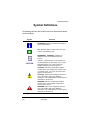
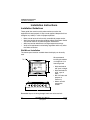
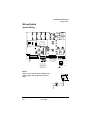
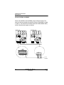
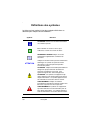
Panneau à distance
Remote Panel
Manuel de l’utilisateur
301EMRP
User Manual
ERP 511395
2/07
301EMRP
User Manual
ERP 511395
2/07
Notices and Trademarks
Copyright by Honeywell International Inc.
Release 511395 February 2007
While this information is presented in good faith and believed to be accurate,
Honeywell disclaims the implied warranties of merchantability for a particular
purpose and makes no express warranties except as may be stated in its
written agreement with and for its customers.
In no event is Honeywell liable to anyone for any indirect, special or
consequential damages. The information and specifications in this document
are subject to change without notice.
Honeywell Analytics
4005 Matte Blvd, Unit G
Brossard, Quebec, J4Y 2P4
511395
2/07
301EMRP User Manual
Honeywell
iii
Contacts
World Wide Web
The following Honeywell Websites may be of interest to our customers:
Honeywell Organization
Honeywell Analytics
Corporate
International
WWW Address (URL)
http://www.honeywellanalytics.com
http://www.honeywell.com
http://content.honeywell.com/global/
Telephone
Contact us by telephone at the numbers listed below:
Organization
United States
and Canada
Asia Pacific
Europe
Latin America
Honeywell Analytics
Honeywell Asia Pacific Inc.
Hong Kong
Honeywell Pace
Brussels, Belgium
Honeywell International Inc.
Sunrise, Florida, U.S.A.
Phone Number
1-800-563-2967
1-450-619-2450
Fax: 1-888-967-9938
(852) 23 31 9133
[32-2]728-2711
(954) 845-2600
Sales Informations
Contact us at [email protected]
511395
2/07
301EMRP User Manual
Honeywell
v
Symbol Definitions
Symbol Definitions
The following table lists the symbols used in this document to denote
certain conditions:
Symbol
Definition
ATTENTION: Identifies information that requires
special consideration
TIP: Identifies advice or hints for the user, often
in terms of performing a task
REFERENCE _ INTERNAL: Identifies an
additional source of information within the
bookset.
CAUTION
511395
2/07
Indicates a situation which, if not avoided, may
result in equipment or work (data) on the system
being damaged or lost, or may result in the
inability to properly operate the process.
CAUTION: Indicates a potentially hazardous
situation which, if not avoided, may result in minor
or moderate injury. It may also be used to alert
against unsafe practices.
CAUTION: Symbol on the equipment refers the
user to the product manual for additional
information. The symbol appears next to required
information in the manual.
WARNING: Indicates a potentially hazardous
situation which, if not avoided, could result in
serious injury or death.
WARNING symbol on the equipment refers the
user to the product manual for additional
information. The symbol appears next to required
information in the manual.
301EMRP User Manual
Honeywell
vii
Contents
INTRODUCTION ............................................................11
Description ............................................................................................ 11
Unpacking ............................................................................................. 11
INSTALLATION INSTRUCTIONS ..................................12
Installation Guidelines ....................................................................... 12
Wall Mount Installation .......................................................................... 12
Wiring Details .................................................................................... 13
System Wiring ....................................................................................... 13
CALIBRATION / PROGRAMMING ................................16
User Interface ........................................................................................ 16
Programming ..................................................................................... 16
Key Definitions ...................................................................................... 16
Specifications .................................................................................... 17
MAINTENANCE .............................................................18
Periodic Inspections and Calibration ................................................. 18
Replacement Parts ................................................................................ 18
Cleaning ................................................................................................ 18
LIMITED WARRANTY ....................................................13
Limited Warranty .................................................................................. 13
Re-Stocking Policy ................................................................................ 13
Exclusions ............................................................................................. 14
Warranty Limitation and Exclusion ........................................................ 14
Disclaimer of Unstated Warranties ........................................................ 15
Limitation of Liability .............................................................................. 15
511395
2/07
301EMRP User Manual
Honeywell
ix
INTRODUCTION
INTRODUCTION
Description
The 301EMRP has been designed to connect to a 301EM network,
which can host up to 10 301EMRP units to ensure efficient air control.
These units display the network status and perform actions
programmed in the 301EM.
Although the 301EMRP is designed to perform actions programmed in
the 301EM, it is possible to program some functions using the display
screen and keypad. The 301EMRP is designed with 4 separate relays,
each capable of receiving one accessory.
Unpacking
After opening the package, remove the equipment and components.
Please make sure that all the items described on the order form or
packing slip are actually in the box and are undamaged.
511395
2/07
301EMRP User Manual
Honeywell
11
Installation Instructions
Installation Guidelines
Installation Instructions
Installation Guidelines
These guide lines must be strictly observed to assure that the
equipment will work properly. If they are not applied, Honeywell will not
recognize any liability in case of improper operation:
•
•
•
•
Make sure to locate all units easily accessible for proper service.
Avoid any location where units could be subject to vibrations.•Avoid
any location close to any electromagnetic interference.
Avoid any location where there are large temperature swings.
Verify local requirements and existing regulations witch may affect
the choice of location.
Wall Mount Installation
The remote panel must be installed where the display can be easily
read.
We recommend
installing the monitor
at a height of 1.5 m
from the ground.
• Mark two holes 6
3/8” apart in height
• Mark two holes10
9/16” apart in
width
• Drill 1/4” holes and
prepare as
necessary
• Mount unit with
appropriate
screws
Remember to pass all wiring through knock-outs at base of unit.
12
301EMRP User Manual
Honeywell
511395
2/07
Installation Instructions
Wiring Details
Wiring Details
System Wiring
EOL Positions
LCD screen
R
Disabled
RC
VJ8
Next
V+
J9
J16
Contact
input
V+
V-
J16 : Manual input switch
Previous
Previous
Next
J8: 3 24 Vdc outputs
RELAY OUTPUTS
6
4
2
J9: 4 4-20 outputs
COMMUNICATION
Communication Wire Gauge:
2-24 AWG (Belden 9841)
Twisted and shielded cable
1000 feet (305 m) per channel
T-tap: 65 feet (20 m) / T-tap
130 feet (40 m) total
Power
Refer to your specific network diagram for
power supply wire gauge (black and red
wires).
5
3
Normally
open
3+5
4+6
Normally
1 closed
1+3
2+4
RISK OF ELECTRIC SHOCK
V+ V-
V+ V-
511395
2/07
301EMRP User Manual
Honeywell
13
Installation Instructions
Wiring Details
Connect 301EM to 301EMRP
Connect the 301EM to the 301EMRP using the diagram below. The
maximum distance between the 301EM and the last 301EMRP is 1000
ft. (305 m). Use twisted and shielded cable #24/2 AWG (Belden 9841)
for the Communication (green and white).
301EMRP PCB
301EM PCB
EOL Positions
EOL Positions
LCD screen
écran à CL
Disabled
R
LCD screen
écran à CL
Disabled
RC
J
1
6
VAC
OUT
R
RC
V+ V-
V+ V-
V+ V-
V+ V-
GND
BLACK
A
WHITE
B
GREEN
SHIELD
A
B
A
B
301EM TERMINAL
301EMRP TERMINAL
14
301EMRP User Manual
Honeywell
To next
301EMRP
511395
2/07
Installation Instructions
Wiring Details
Relay Outputs
The relays outputs will withstand up to 5
amps at 30 Vdc or 250 Vac (resistive
load only). They can be used to activate
horns, strobes, etc. Refer to drawing
below for proper wiring.
See APPENDIX section in the 301EM
User’s Manual for more details about B52 and ASHRAE standard configuration.
RELAY OUTPUTS
6
4
5
2
3
1
Normally
open
3+5
4+6
Normally
closed
1+3
2+4
RISK OF ELECTRIC SHOCK
Output 24 Vdc, J8
The three 24 Vdc / 250 mA outputs are provided to activate DC horn,
strobe, etc.
RFS: Optional built-in stobe
RFSA: Optional built-in stobe and horn
511395
2/07
301EMRP User Manual
Honeywell
15
CALIBRATION / PROGRAMMING
Programming
CALIBRATION / PROGRAMMING
User Interface
When power is initially applied, the unit’s LCD screen will display the
product’s name and firmware revision.
Programming
The 301EMRP (remote panel) actions are programmed in the 301EM
(see 301EM User Manual, Appendix section). The unit performs the
programmed actions depending on what accessories are connected to
the unit. The 301EMRP addresses must be programmed on each unit
to enable them to receive information from the 301EM. Once the
addresses are programmed, the 301EM will detect the remote panels
through network scans.
Key Definitions
ESC Key:
(Up/Down):
Enter Key:
Fan Start Key:
Silence Key:
16
Use the ESC Key to exit the menus or cancel an
input. Use it also to stop the alternating reading
between the connected sensors.
Use the Scroll Keys to scroll the menus or to select a
specific value.
Use the Enter Key to enter a programming field or to
validate a specific value.
Control relay #1 (Fan)
(For B-52 or ASHRAE 15 programming).
Turns off the buzzer and horns
301EMRP User Manual
Honeywell
511395
2/07
CALIBRATION / PROGRAMMING
Specifications
Specifications
Remote Panel 301EMRP
Power Requirement:
22-27 Vac, 50/60 Hz,
29-38Vdc, 2.0 A max @ 24 Vdc
4 DPDT relays
3 Outputs at 24 Vdc @ 250 mA each
65 dBA @ 3 foot (1 m)
Backlit LCD
Green LED: Normal operation
Red LEDs: Alarm A, B and C
Yellow LED: Fault/service alarm
Amber LED: Tx (Activated in network
mode)
1000 ft. between 301EM and 301EMRP
Standard Outputs:
Audible Alarm:
Display :
Visual Indicators:
Communication
(length of lines)
Relay Output Rating:
Circuit Protection:
Overvoltage Category:
Power Requirement:
Operating Environnement:
Operating Temperature
Range:
Operating Humidity Range:
Operating Altitude:
Enclosure:
Pollution Degree:
Size:
Weight:
Optional Horn:
Optional Strobe:
511395
2/07
5A, 30Vdc or 250Vac (resistive load)
Long Time-Lag Polyswitch Type TT
II
22-27 Vac, 50/60 Hz,
29-38Vdc, 2.0 A max @ 24 Vdc
Indoor use
32°F to 100°F (0 to 40°C)
0 to 95% RH (non-condensing)
Up to 9843 feet (3,000 m)
NEMA 4X ABS - Polycarbonate
2
7.99” (H) x 11.02”(W) x 2.76” (D)
(20.3 x 28 x 7 cm)
2.26 lbs (1.02 kg)
105dBA, 4-28V, 2800Hz (RFSA)
Min. Voltage 80 dB(A) min. @ 2 ft and 6
Vdc
Max Voltage 90 dB(A) min. @ 2 ft and 28
Vdc
STAS flashing LED, 24VAC/VDC
301EMRP User Manual
Honeywell
17
MAINTENANCE
Periodic Inspections and Calibration
MAINTENANCE
The 301EMRP is a maintenance free controller. Only the sensors need
periodic inspection.
Periodic Inspections and Calibration
Honeywell provides its customers with specialized gas detection
equipment. Beyond the warranty period, the systems must be
maintained on a regular basis.
Replacement Parts
LED replacement instructions (for RFS or RFSA options):
•
•
•
•
•
•
Turn the cap until the black and white diamond shapes are aligned
Pull off the cap
Use the insertion tool to remove the LED
Use the insertion tool to put in the new LED
Put the cap back on
Turn the cap until the white diamond shapes are aligned.
Due to the continuous evolution of our products, please contact our
service department to order parts or for more details.
Cleaning
Clean the exterior with a soft, damp cloth. Do not use solvents, soaps
or polishers.
18
301EMRP User Manual
Honeywell
511395
2/07
Limited Warranty
Limited Warranty
Limited Warranty
Honeywell Analytics, Inc. warrants to the original purchaser and/or
ultimate customer ("Purchaser") of Vulcain products ("Product") that if
any part thereof proves to be defective in material or workmanship
within twelve (12) months, such defective part will be repaired or
replaced, free of charge, at Honeywell Analytics' discretion if shipped
prepaid to Honeywell Analytics at 4005 Matte Blvd., Unit G, Brossard,
Quebec, J4Y 2P4, in a package equal to or in the original container.
The Product will be returned freight prepaid and repaired or replaced if
it is determined by Honeywell Analytics that the part failed due to
defective materials or workmanship. The repair or replacement of any
such defective part shall be Honeywell Analytics' sole and exclusive
responsibility and liability under this limited warranty.
Re-Stocking Policy
The following re-stocking fees will apply when customers return
products for credit:
•
15% re-stocking fee will be applied if the product is returned within
1 month following the shipping date
•
30% re-stockingfee will be applied if the product is returned within 3
months following the shipping date
A full credit (less re-stocking fee) will only be issued if the product is in
perfect working condition. (If repairs are required on the returned
product, the cost of these repairs will be deducted from the credit to be
issued.)
No credits will be issued beyond the three month period.
511395
2/07
301EMRP User Manual
Honeywell
19
Limited Warranty
Exclusions
a.If Gas sensors are part of the Product, the gas sensor is covered
by a twelve (12) month limited warranty of the manufacturer.
b.If gas sensors are covered by this limited warranty, the gas
sensor is subject to inspection by Honeywell Analytics for extended
exposure to excessive gas concentrations if a claim by the
Purchaser is made under this limited warranty. Should such
inspection indicate that the gas sensor has been expended rather
than failed prematurely, this limited warranty shall not apply to the
Product.
c.This limited warranty does not cover consumable items, such as
batteries, or items subject to wear or periodic replacement,
including lamps, fuses, lves, nes, sensor elements, cartridges, or
filter elements.
Warranty Limitation and Exclusion
Honeywell Analytics will have no further obligation under this limited
warranty. All warranty obligations of Honeywell Analytics are
extinguishable if the Product has been subject to abuse, misuse,
negligence, or accident or if the Purchaser fails to perform any of the
duties set forth in this limited warranty or if the Product has not been
operated in accordance with instructions, or if the Product
serial number has been removed or altered.
20
301EMRP User Manual
Honeywell
511395
2/07
Limited Warranty
Disclaimer of Unstated Warranties
The warranty printed above is the only warranty applicable to this
purchase. All other warranties, express or implied, including, but not
limited to, the implied warranties of merchantability or fitness for a
particular purpose are hereby disclaimed.
Limitation of Liability
It is understood and agreed that Honeywell Analytics’ liability, whether
in contract, in tort, under any warranty, in negligence or otherwise shall
not exceed the amount of the purchase price paid by the purchaser for
the product and under no circumstances shall Honeywell Analytics be
liable for special, indirect, or consequential damages. The price stated
for the product is a consideration limiting honeywell analytics' liability.
No action, regardless of form, arising out of the transactions under this
warranty may be brought by the purchaser more than one year after the
cause of actions has occurred.
511395
2/07
301EMRP User Manual
Honeywell
21
301EMRP
Manuel d’utilisateur
ERP 511395
2/07
Avis et marques de commerce
Tous droits réservés par Honeywell International Inc.
Parution 511395 February 2007
Quoique cette information est présentée en bonne foi et est présumée exacte,
Honeywell décline la garantie tacite de la qualité marchande pour un emploi
particulier et offre aucune garantie exprès, à l’exception des conventions écrites
avec et pour ses clients.
Honeywell ne sera, sous aucune circonstance, responsable à qui que ce soit
pour des dommages spéciaux ou indirectes. Les informations et les
spécifications dans ce document sont susceptibles d’être modifiées sans
préavis.
Honeywell Analytics
4005 Matte Blvd, Local G
Brossard, Québec, J4Y 2P4
511395
2/07
Manuel de l’utilisateur 301EMRP
Honeywell
iii
Nous joindre
Web
Les sites Web suivant d’Honeywell peuvent être utilies pour nos clients :
Organisation Honeywell
Honeywell Analytics
Corporate
International
Adresses WWW (URL)
http://www.honeywellanalytics.com
http://www.honeywell.com
http://content.honeywell.com/global/
Téléphone
Utiliser les numéros de téléphone ci-dessous pour nous contacter :
Organisation
États Unis
et Canada
Asie Pacifique
Europe
Amérique latine
Honeywell Analytics
Honeywell Asia Pacific Inc.
Hong Kong
Honeywell Pace
Bruxelles, Belgique
Honeywell International Inc.
Sunrise, Floride, É.U.
Numéro de téléphone
1-800-563-2967
1-450-619-2450
Fax: 1-888-967-9938
(852) 23 31 9133
[32-2]728-2711
(954) 845-2600
Informations des ventes
Nous contacter à [email protected]
511395
2/07
Manuel de l’utilisateur 301EMRP
Honeywell
v
Définitions des symboles
Le tableau suivant contient la liste des symboles utilisés dans ce
document pour indiquer certaine conditions :
Symbole
Définition
ATTENTION: Identifie une information demandant
une attention spéciale
Truc: Identifie un conseil ou un truc pour
l’utilisateur, souvent concernant une tâche
RÉFÉRENCE- INTERNE Indique une source
d’information supplémentaire à l’intérieur du
document.
ATTENTION
511395
2/07
Indique une situation à éviter pouvant entraîner des
dommages au système ou la perte de travail
(documents) ou pouvant prévenir l’opération
normale du système.
ATTENTION : Indique une situation potentiellement
dangereuse qui peut entraîner des blessures
mineures ou modérées si pas évité. Peut
également signaler des actions dangereuses
ATTENTION: Un symbole sur l’équipement qui
réfère l’utilisateur à la documentation pour de plus
amples informations. Ce symbole apparaît à côté
des informations nécessaires dans le manuel.
AVERTISSEMENT : Indique une situation
potentiellement dangereuse qui peut entraîner des
blessures majeures ou la mort si pas évité.
AVERTISSEMENT Un symbole sur l’équipement
qui réfère l’utilisateur à la documentation pour de
plus amples informations. Ce symbole apparaît à
côté des informations nécessaires dans le manuel.
Manuel de l’utilisateur 301EMRP
Honeywell
vii
Tables des matières
INTRODUCTION ...........................................................11
Description ....................................................................................... 11
Déballage ......................................................................................... 11
INSTRUCTIONS D’INSTALLATION .............................12
Directives d’installation ..................................................................... 12
Installation Murale ................................................................................ 12
DÉTAILS DE CONNEXION ...........................................13
Câblage du système ......................................................................... 13
INTERFACE USAGER ..................................................16
Programmation ...................................................................................... 16
Description des touches ........................................................................ 16
Spécifications ................................................................................... 17
Pannéeau à distance 301EM RP .......................................................... 17
ENTRETIEN ....................................................................18
Inspection périodique et étalonnage ................................................ 18
Pièces de remplacement ...................................................................... 18
Nettoyage ............................................................................................. 18
GARANTIE LIMITÉE ......................................................19
Garantie limitée ..................................................................................... 19
Politique de Retour ................................................................................ 19
Exclusions ............................................................................................. 20
Limitation et exclusion de la garantie .................................................... 20
Dénégation de responsabilité d’autres garanties .................................. 21
Limitation de responsabilité ................................................................... 21
511395
2/07
Manuel de l’utilisateur 301EMRP
Honeywell
ix
Introduction
Description
Introduction
Description
Le 301EMRP est conçu pour la connexion au réseau d’un 301EM,
pouvant accueillir jusqu’ à 10 unités EMRP, ce qui assure un contrôle
de l’air plus efficace. Ces unités affichent le statut du réseau et
affectuent les actions programmées depuis le 301EM.
Quoique les 301EMRP est conçu pour effectuer les tâches
programmés depuis le 301EM, son écran à CL et son clavier
permettent d’effectuer certaines programmation directement sur l’unité.
Le 301EMRP comporte 4 relais séparés, chacun pouvant acceuilir un
accessoire.
En outre, il offre des sorties 4@20 mA et relais, une communication
Modbus, des options d'alarmes sonores et il est compatible avec notre
contrôleur 301C.
Déballage
Dès l’ouverture de l’emballage, assurez-vous que vous avez reçu
l’équipement et les composantes tels qu’indiqués sur le bon de
connaissement et que l’ensemble de la commande n’est pas
endommagé.
511395
2/07
Manuel de l’utilisateur 301EMRP
Honeywell
11
Instructions d’installation
Directives d’installation
Instructions d’installation
Directives d’installation
Ces directives doivent être strictement respectées pour assurer le
bon fonctionnement de l’équipement. Si elles ne sont pas suivies,
Honeywell ne se tiendra aucunement responsable des incidents
pouvant en découller:
•
•
•
•
•
Localiser chaque unité à un endroit facile d’accès pour un
technicien.
Éviter toute localisation des unités près des sources de vibrations.
Évitez d’installer les unités près d’équipements émettant des
interférences électromagnétiques.
Évitez les emplacements où la température change rapidement.
Avant de débuter l’installation, vérifiez tous les codes, normes ou
législations pouvant affecter le choix de l’emplacement.
Installation Murale
Le panneau à distance devrait être installé à une hauteur où l’afficheur
est visible.
.Nous recommandons l’installation
de l’unité à 1.5 m (5pi) du sol.
• Mesurer les 2 trous verticaux à
6 3/8”
• Mesurer les 2 trous horizontaux
à 10 9/16”
• Perçer et préparer les trous de
montage 1/4” diamètre
• Fixer l’unité avec les vis
appropriés
Passer tout câblage par les trous
poinçonnés (knock-out).
12
Manuel de l’utilisateur 301EMRP
Honeywell
511395
2/07
Détails de connexion
Câblage du système
Détails de connexion
Câblage du système
Positions cavalier
fin de ligne
Désactivé
Suivant
R
Écran
affichage à CL
RC
V-
J8
V+
J9
J16
Contact
input
V+
V-
Précédent
Précédent
Suivant
COMMUNICATION
Calibre de câble de
Communication:
2-24 AWG (Belden 9841)
câble torsadé et blindé
305 m (1000 pi) par canal
T-tap: 20 m (65 pi) / T-tap
40 m (130 pi) total
J16 :Entrée commutateur manuel
J8:3 sorties 24 Vcc
J9:4 sorties 4@20
Alimentation
Consulter votre diagramme de réseau
pour connaître le calibre de câblage
d’alimentation (fils noir et rouge).
SORTIES RELAIS
6
4
5
2
3
Normalement 3+5
ouvert
4+6
1 Normalement 1+3
fermé
2+4
RISQUE DE CHOC ÉLECTRIQUE
V+ V-
V+ V-
I
511395
2/07
Manuel de l’utilisateur 301EMRP
Honeywell
13
Détails de connexion
Câblage du système
Détails de connexion du 301EM au 301EMRP
Connecter le the 301EMRP au 301EM selon le dessin ci-dessous. La
distance entre le 301EM et le 301EMRP ne doit pas excéder 305 m
(1 000 pi.).
301EMRP PCB
301EM PCB
Positions cavalier EOL
Positions cavalier EOL
LCD screen
écran à CL
désactivé R
LCD screen
écran à CL
désactivé R
RC
RC
J
1
6
V+ V-
V+ V-
V+ V-
V+ V-
GND
BLACK
A
WHITE
B
GREEN
SHIELD
A
B
A
B
Borne 301EM
Borne 301EMRP
14
Manuel de l’utilisateur 301EMRP
Honeywell
Au 301EMRP
suivant
511395
2/07
Détails de connexion
Câblage du système
Sorties relais
Les sorties de relais résisteront jusqu'à 5
ampères à 30 Vcc ou à 250 Vca (charge
résistive seulement). Elles peuvent être
utilisées pour activer des alarmes
sonores, stroboscopes, etc.
Voir la section ANNEXE pour les détails
des configurations pour les normes B-52
et ASHRAE 15.
SORTIES RELAIS
6
4
5
2
3
Normalement 3+5
ouvert
4+6
Normalement 1+3
1 fermé
2+4
RISQUE DE CHOC ÉLECTRIQUE
Sortie 24 Vcc, Borne J8
Les trois sorties 24 Vcc / 250mA servent à activer le klaxon.
stroboscope, etc.
RFS: Optional built-in stobe
RFSA: Optional built-in stobe and hornÉtalonnage / Programmation
511395
2/07
Manuel de l’utilisateur 301EMRP
Honeywell
15
Interface Usager
Câblage du système
Interface Usager
Quand l'appareil est initialement mis sous tension, l'unité affiche le
numéro de modèle et de révision du logiciel.
Programmation
Les actions du 301EMRP sont programmées dans le 301EM. Le
301EMRP reproduit ces actions d’après les accessoires connectés à
ses relais. Les adresses des 301EMRP sont programmées sur chaque
unité. Ceci permet aux 301EM de reconnaître tous les 301EMRP sur le
réseau. Si aucune adresse n’est programmée dans un 301EMRP, il ne
sera pas détecté.
Description des touches
ESC
La touche “ESC” permet de canceller une entrée ou
sortir du mode de programmation. Utiliser la touche
ESC pour arrêter de déroullement de l’affichage sur
une sonde en particulier.
Flèches haut/bas Les flèches “haut/bas” servent à parcourir les menus
et à confirmer une valeur dans un menu.
Enter
La touche “Enter” permet de mettre le 301EM en
mode de programmation et à valider une valeur dans
un menu.
Fan Start
La touche “Fan” contrôle le relais #1 (Programmation
B-52 OU ASHRAE 15). Voir annexe
Fan Stop/Reset Cette touche permet de rétablir l’alarme ou le relais
#1 lorsqu’une configuration de base B-52 ou
ASHRAE 15 a été programmée. Voir annexe
Silence
La touche “Silence”permet d’éteindre l’avertisseur
sonore et les sirènes.
16
Manuel de l’utilisateur 301EMRP
Honeywell
511395
2/07
Interface Usager
Spécifications
Spécifications
Pannéeau à distance 301EM RP
Alimentation requise :
Sorties :
22 - 27 Vca, 50/60 Hz
29 - 38Vcc, 1 A @ 29 Vcc
4 relais DPDT
3 sorties x 24 Vcc, 250 mA chaque
Alarme sonore :
65 dBA à 1 mètre
Affichage :
Afficheur à CL rétroéclairé
Indicateurs visuels :
Opération Normal : DEL vert
Alarmes A, B et C : DELs rouges
Faute/alarme de service : DEL jaune
Tx : (Activé en mode réseau) DEL jaune
Longueur de lignes :
Spécifications relais :
Protection de circuit :
305 m (1000 pi) entre 301EM et 301EMRP
T-tap: maximum 20m (65pi.) par T-tap 40 m (130 pi.)
total
5A, 30 Vcc ou 250 Vca (charge résistive)
Fusible réarmable PolySwitch de type TT, à délai
prolongé
Utilisation à l’intérieur
Environnement de
fonctionnement :
Catégorie de
II
surtension :
Plage de température : 0°C à 40°C
Plage d’humidité :
0% à 95% RH (non-condensé)
Altitude de
Jusqu’à 3 000 m (9843’)
fonctionnement :
Boîtier :
NEMA 4X Polycarbonate - ABS
Degré de polution :
2
Dimensions :
20,3 cm (H) x 28 cm (L) x 7 cm (P)
7,99’’ (H) x 11,02’’ ( W ) x 2,76’’ (D)
Poids :
1,02 Kg (2.26lbs)
Sirène optionelle:
105dBA, 4-28V, 2800Hz (RFSA)
Voltage min. 80 dB(A) min. @ 2 pi. et 6 Vcc
Voltage max. 90 dB(A) min. @ 2 pi. et 28 Vcc
Stroboscope optionel : DEL STAS clignotante, 24Vca/Vcc
511395
2/07
Manuel de l’utilisateur 301EMRP
Honeywell
17
Entretien
Inspection périodique et étalonnage
Entretien
Le 301EM ne nécessite aucune maintenance. Par contre, les
transmetteurs nécessitent une inspection périodique.
Inspection périodique et étalonnage
Honeywell fournit à ses clients des équipements de détection de gaz
spécialisés. Au-delà de la période de garantie, ces systèmes doivent
être entretenus sur une base régulière.
Pièces de remplacement
Instructions de remplacement des DELs pour les options RFS et
RFSA
• Tourner le diamant sur le capuchon de la lentille jusqu’à ce qu’il soit
aligné avec le diamant noir de la lentille;
• Retirer le capuchon;
• Utiliser l’outil d’insertion afin de retirer le DEL;
• Utiliser l’outil d’insertion afin de placer le nouveau DEL;
• Replacer le capuchon;
• Tourner le diamant sur le capuchon de la lentille jusqu’à ce qu’il soit
aligné avec le diamant blanc de la lentille.
En raison de la constante évolution de nos produits, veuillez contacter
le support technique pour plus de détails.
Ligne Support Technique: 1 800 563-2967
Nettoyage
Nettoyer l’extérieur de l’unité avec un linge humide et doux. Ne pas
utiliser de solvant, de savon ou de polis.
18
Manuel de l’utilisateur 301EMRP
Honeywell
511395
2/07
Garantie limitée
Garantie limitée
Garantie limitée
Honeywell Analytics, Inc. garantie à l’Acheteur d’origine et/ou au client
final (« Acheteur ») de produits Vulcain (« Produit ») que si une pièce
quelconque du produit s’avère défectueuse , soit en matériel ou en
main d’oeuvre, dans les douze (12) mois, cette pièce sera réparée ou
remplacer, sans frais, à la discrétion d’Honeywell Analytics si expédié,
port payé, à Honeywell Analytics at 4005 Matte Blvd., Unit G, Brossard,
Quebec, J4Y 2P4, dans l’emballage d’origine ou l’équivalent. Le Produit
sera retourné au client port payé si Honeywell Analytics détermine que
la pièce est défectueuse en raison de défaut matériel ou de main
d’oeuvre. La réparation ou le remplacement d’une telle pièce
défectueuse représente la seule et exclusive responsabilité
d’Honeywell Analytics sous cette garantie limitée.
Politique de Retour
Les frais suivants seront applicables lors de retour de produit pour
crédit :
•
Des frais de retour de 15% seront appliqués lorsque le produit est
retourné dans le 1er mois suivant la date d’expédition
•
Des frais de retour de 30% seront appliqués lorsque le produit est
retourné dans les 3 mois suivant la date d’expédition
Un crédit total (moins les frais de retour) sera uniquement appliqué si le
produit est en parfait état de fonctionnement. Si des réparations sont
nécessaires sur le produit retourné, les frais de cette réparation seront
déduit du crédit.
Auncuns crédits ne seront appliqués pour les retours après les 3 mois
suivant la date d’expédition.
511395
2/07
Manuel de l’utilisateur 301EMRP
Honeywell
19
Garantie limitée
Exclusions
A. Si des capteurs de gaz font partie du Produit, le capteur est
couvert par une garantie limitée de douze (12) mois du fabricant.
B. Si les capteurs de gaz sont couverts par cette garantie limitée,
le capteur sera assujeti à l’inspection par Honeywell Analytics pour
l’exposition prolongée à des concentrations de gaz élevées si
l’Acheteur fait une réclamation sous cette garantie limitée. SI
l’inspection indique que la cause de la défectuosité est l’épuisement du
capteur plutôt qu’un défaut, cette garantie ne s’appliquera pas au
Produit.
C. Cette garantie limitée ne s’applique pas au produits
consommables, tels les piles, ou les articles sujets à l’usure ou au
remplacement régulier, incluant les lampes, les fusibles, les valves, les
aubes, les élements de sonde, les cartouches ou les éléments de
filtres.
Limitation et exclusion de la garantie
Honeywell Analytics n’aura aucun autre responsabilité sous cette
garantie limitée. Toutes responsabilités de garantie d’Honeywell
Analytics sont annulées si le Produit a subi des abus, de la
négligeance, un accident ou si l’Acheteur est en défaut de ses
obligations tels que décrit dans cette garantie ou si le Produit n’a pas
été utilisé selon les instructions ou si le numéro de série du Produit été
enlevé ou modifié.
511395
2/07
Manuel de l’utilisateur 301EMRP
Honeywell
20
Garantie limitée
Dénégation de responsabilité d’autres garanties
La garantie ci-haut est la seule garantie applicable à cet achat. Toutes
autres garanties, soit implicites ou exprès, incluant mais pas limité à,
les garanties tacites de qualité marchande ou de l’aptitude à un emploi
particulier sont dénéguées par le présent document.
Limitation de responsabilité
Il est entendu que la responsabilité d’Honeywell Analytics, soit en
contrat, en délit civil, sous n’importe quelle garantie de responsabilité,
en négligence ou autrement n’excédera pas le prix d’achat payé par
l’Acheteur pour le produit. Honeywell Analytics ne sera pas
responsable, sous aucune circonstance, pour des dommages spéciaux
ou indirectes. Le prix déclaré pour le produit est une considération
limitant la responsabilité d’Honeywell Analytics. Aucune action, en
quelle forme que soit, survenant des transactions sous cette garantie
peuvent être entreprises par l’Acheteur plus d’un an après l’occurence
de la cause de ces actions.
511395
2/07
Manuel de l’utilisateur 301EMRP
Honeywell
21