1
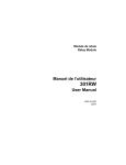
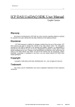
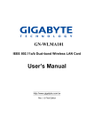
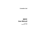
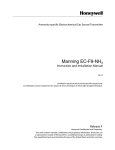
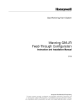
Analog Digital Input Converter
301ADI
User Manual
ERP 510846
4/07
Notices and Trademarks
Copyright 2006 by Honeywell International Inc.
Release 510846 April 2007
While this information is presented in good faith and believed to be accurate,
Honeywell disclaims the implied warranties of merchantability for a particular
purpose and makes no express warranties except as may be stated in its
written agreement with and for its customers.
In no event is Honeywell liable to anyone for any indirect, special or
consequential damages. The information and specifications in this document
are subject to change without notice.
Other brand or product names are trademarks of their respective owners,
Honeywell Analytics
4005 Matte Blvd, Unit G
Brossard, Quebec, J4Y 2P4
510846
4/07
301ADI User Manual
Honeywell
iii
Contacts
World Wide Web
The following Honeywell Websites may be of interest to our customers:
Honeywell Organization
Honeywell Analytics
Corporate
International
WWW Address (URL)
http://www.honeywellanalytics.com
http://www.honeywell.com
http://content.honeywell.com/global/
Telephone
Contact us by telephone at the numbers listed below:
Organization
United States
and Canada
Asia Pacific
Europe
Latin America
Honeywell Analytics
International Inc.
Honeywell Asia Pacific Inc.
Hong Kong
Honeywell Pace
Brussels, Belgium
Honeywell International Inc.
Sunrise, Florida, U.S.A.
Phone Number
1-800-563-2967
1-450-619-2450
Fax: 1-888-967-9938
(852) 23 31 9133
[32-2]728-2711
(954) 845-2600
Sales Informations
Contact us at [email protected]
510846
4/07
301ADI User Manual
Honeywell
v
Symbol Definitions
The following table lists the symbols used in this document to denote
certain conditions:
Symbol
Definition
ATTENTION: Identifies information that requires
special consideration
TIP: Identifies advice or hints for the user, often
in terms of performing a task
REFERENCE _ INTERNAL: Identifies an
additional source of information within the
bookset.
CAUTION
510846
4/07
Indicates a situation which, if not avoided, may
result in equipment or work (data) on the system
being damaged or lost, or may result in the
inability to properly operate the process.
CAUTION: Indicates a potentially hazardous
situation which, if not avoided, may result in minor
or moderate injury. It may also be used to alert
against unsafe practices.
CAUTION: Symbol on the equipment refers the
user to the product manual for additional
information. The symbol appears next to required
information in the manual.
WARNING: Indicates a potentially hazardous
situation which, if not avoided, could result in
serious injury or death.
WARNING symbol on the equipment refers the
user to the product manual for additional
information. The symbol appears next to required
information in the manual.
301ADI User Manual
Honeywell
vii
Contents
SAFETY INSTRUCTIONS ..............................................11
INTRODUCTION ............................................................12
Receiving and Verification ..................................................................... 12
INSTALLATION ..............................................................13
Installation Guidelines ....................................................................... 13
Wall Mount Installation ...................................................................... 14
Mounting Instructions ............................................................................ 14
WIRING DETAILS 301ADI .............................................15
Wiring Instructions ................................................................................. 16
CONFIGURATION ..........................................................17
Accessing the Menus ........................................................................ 17
CfgAI Menu Options .......................................................................... 18
ConfigDI Menu Options ..................................................................... 18
SPECIFICATIONS ..........................................................20
Communication Protocol ................................................................... 20
LED Indicators ....................................................................................... 20
Technical Specifications .................................................................... 21
Maintenance and Care .......................................................................... 21
510846
4/07
301ADI User Manual
Honeywell
ix
ANNEX A ........................................................................ 23
301ADI/420MDBS Technical Bulletin ................................................23
Reading Value Scale Formulas .............................................................23
LIMITED WARRANTY ................................................... 25
Limited Warranty ....................................................................................25
Re-Stocking Policy .................................................................................25
Exclusions ..............................................................................................26
Warranty Limitation and Exclusion .........................................................26
Disclaimer of Unstated Warranties ........................................................27
Limitation of Liability ...............................................................................27
x
301ADI User Manual
Honeywell
510846
4/07
Safety Instructions
Safety Instructions
To ensure safety, this equipment must be serviced by qualified
Honeywell personnel or certified service technicians only.
•
•
•
•
•
•
Read and understand the user manual completely before operating
or servicing the equipment.
Substituting components may severely impair product safety.
Perform regular equipment inspections and keep an inspection log.
Contact Honeywell immediately if the unit is damaged or is missing
parts.
Do not use the product if any components/parts are damaged.
Do not expose the unit to electrical shocks or to prolonged, severe
mechanical shock.
Do not disconnect or replace any parts unless the power has been
shut off or unless the area has been certified non-hazardous.
510846
4/07
301ADI User Manual
Honeywell
11
Introduction
Introduction
The 301ADI is a
microprocessor based
converter unit for use with
Honeywell control units, such
as the 301C.
Power
Fault
TX
TX
The 301ADI LCD display
screen, enclosed in the
housing, serves as a
programming interface.
Analog Digital Input Converter
301ADI
The unit has 3 LED
indicators, 16 (loop) inputs
that read 4-20mA signals and 8 contact inputs that read contact, or
relay signals.
Receiving and Verification
Before proceeding to the installation instructions, you must first verify
the equipment and any components. Please make certain that no
equipment or component is missing, that all items match those listed on
the order form (or packing slip) and that none of the equipment is
damaged.
12
301ADI User Manual
Honeywell
510846
4/07
Installation
Installation Guidelines
Installation
The 301ADI must be installed according to the following installation
instructions to ensure proper functioning of the unit.
Note: Failure to respect the installation instructions provided by
Honeywell may result in improper functioning of the unit, for which
Honeywell will not be held responsible or liable in any way.
Installation Guidelines
The 301ADI converter is designed for installation in general purpose
areas. Installation personnel should be qualified technicians. Local
electrical code and safety standards must be observed throughout the
installation.
The following is a list of guidelines that will help ensure that the unit
functions properly and that it is not exposed to conditions that might
affect its performance:
•
•
•
•
•
Locate unit in easily accessible areas to facilitate access for service
Avoid installing unit in locations where it could be subject to
vibrations
Avoid installing the unit close to sources of electromagnetic
interference
Avoid installing the unit in areas subject to significant temperature
swings
Verify local governmental requirements and existing regulations
that might affect the choice of location.
Make sure to disconnect power from the unit before
proceeding to any physical wiring.
510846
4/07
301ADI User Manual
Honeywell
13
Installation
Wall Mount Installation
Wall Mount Installation
The converter should be mounted on a wall where there is minimum
vibration, away from heat and with sufficient ventilation room around
the unit. Its location should be within easy reach of operating
personnel.
301ADI
Power
Fault
TX
16.4 cm
(603/8")
Analog Digital Input Converter
301ADI
26.8 cm
(10 9/16")
Mounting Instructions
1. Select installation location
2. Measure and mark mounting holes (as shown)
3. Pre-drill or prepare as required by mounting surface (drywall plugs,
etc.)
4. Position unit and align mounting holes with markings and install
necessary screws.
Note: Remember to remove knock-outs before mounting the unit.
14
301ADI User Manual
Honeywell
510846
4/07
Wiring Details 301ADI
Wall Mount Installation
Wiring Details 301ADI
The image below is the 301ADI PCB.
Pass the wires up through the knock-outs provided at the bottom of the
unit.
Contact
JP1
U1
J5
8
7
LCD1
C1
5
4
3
1
JP2
SHDN
D2
SW2
ENTER
SW3
SW4
E.O.L.
JP5
DOWN
RC
R
CO
M
JP3
J3
D4
JP4
J2
J4
GND
next
J1
V-
V+
OUT
A
B
SHLD
VDC OUT
IN
SIG
V+
V-
A
B
SHLD
1
2
V + IN
3
4
5
6
7
8
Analog Inputs
9
10
11
12
13
14
15
16
Up to 16 analog inputs
V - IN
previous
B
Communication Wire Gauge:
2-24 AWG (Belden 9841)
Twisted and shielded cable
2000 feet (600 m) per channel
T-tap: 65 feet (20 m) / T-tap
130 feet (40 m) total
Always respect minimum
voltage requirements at device
Passive 4-20mA
configuration or
Loop Powered Device
Passive 4-20mA
configuration or
Loop Powered Device
Passive 4-20mA
configuration or
Loop Powered Device
510846
4/07
[-]
COMMUNICATION
A
120 : 24
Modbus TCP/IP
ESC
D3
04
SW1
1
JP6
UP
C3
Contact
2
D1
C2
Digital Inputs
VDC OUT
6
VRef+1
[+]
[-]
[+]
[-]
[+]
[-]
[+]
Passive 4-20mA
configuration or
Loop Powered Device
Passive 4-20mA
configuration or
Loop Powered Device
Passive 4-20mA
configuration or
Loop Powered Device
[+]
[-]
[+]
[-]
301ADI User Manual
Honeywell
15
Wiring Details 301ADI
Wall Mount Installation
Wiring Instructions
1. Disconnect power supply before proceeding to connect any wiring.
2. Connect the communication wires from the controller's (301C) RS485 port into communication terminals A and B (J1).
3. Connect the transmitter wires to the analog inputs (J2, J4), in SIG
and VDC OUT.
4. Connect the contact device to the digital inputs (J5).
When all connections are complete, you can proceed to the
configuration of the unit.
16
301ADI User Manual
Honeywell
510846
4/07
Configuration
Accessing the Menus
Configuration
Accessing the Menus
The 301ADI is equipped with a 2 x 8 character LCD display screen
within its housing that allows you to configure the settings for the 16
analog inputs and the 8 digital inputs. Use the keypad arrows (Up,
Down, Esc, Enter) provided on the PCB to scroll through programming
options.
When you open the 301ADI housing (to access the display screen), the
LCD screen displays only the product name and the Modbus address.
This is displayed whenever the screen is idle. The programming
function is password protected, you must log a password to access this
function. The default password is VA.
•
•
•
•
•
Press Enter once to display the password screen.
When the password screen is first displayed, it shows PASSWORD
AA
AA as the password, with the cursor under the first
letter.
Use the Up or Down arrow buttons to change characters.
When the first letter is correct, press Enter to move to the second
letter.
Press Enter once more to validate the password.
Once the password has been validated, the screen
displays "*Menu* ConfigAI?", the first of three (3) main
menu options. Use the Up and Down buttons to scroll
through the options and Enter to select the desired one:
•
•
•
*MENU*
Cfg AI
Press the UP button once to move from the Config
*MENU*
AI screen to the Config DI screen (press DOWN to
Cfg DI
return to the previous screen)
Press the UP button again to move to the “Modbs
*MENU*
ID” screen
ModbsID
Pressing ENTER at any screen opens a sub-menu
that allows you to either enable or disable an input or to change the
Modbus address.
510846
4/07
301ADI User Manual
Honeywell
17
Configuration
CfgAI Menu Options
CfgAI Menu Options
The steps below show the "Cfg AI" menu progress for each main menu
option.
ConfigAI En/Dis?
This option lets you configure whether a
transmitter is enabled or not or simply to verify its
status. The screen displays the transmitter
number and whether it is enabled or not.
•
•
•
ConfigAI
En/Dis?
Use the Up and Down buttons to scroll through all 16 analog inputs,
or transmitters.
Use the Enter button to change a transmitter's
A I0 1
status from Enabled to Disabled (depending on
E
n
a b le d
status displayed)
When you are done configuring input statuses,
press ESC to return to the main menu. Pressing ESC will not
cancel the changes you made.
ConfigDI Menu Options
The steps below show the "Cfg DI" menu progress
for each main menu option.
ConfigDI En/Dis?
This option lets you configure whether a
transmitter is enabled or not or simply to verify its
status. The screen displays the transmitter
number and whether it is enabled or not.
•
•
•
18
*MENU*
Cfg DI
ConfigDI
En/Dis?
Use the Up and Down buttons to scroll through all 8 contact inputs.
Use the Enter button to change a contact
D I0 1
input's status from Enabled to Disabled
E n a b le d
(depending on status displayed)
When you are done configuring input statuses,
press ESC to return to the main menu.
Pressing ESC will not cancel the changes you made.
301ADI User Manual
Honeywell
510846
4/07
Configuration
ConfigDI Menu Options
ModbsID Menu Options
This option lets you set a different Modbus address
than the factory set address.
CAUTION
*MENU*
ModbsID
The 301ADI Modbus address must be set to 097 for it to
be recognized by the 301C controller.
When you first access the Modbus ID option, the screen displays the
current address with the first character underlined.
•Use the UP or DOWN buttons to increase or
decrease the character value.
•When the correct value is displayed, press
ENTER.
•Continue until all characters are set as
desired for the new Modbus address
Press ESC to return to the previous menu.
ModbsID
097
•
510846
4/07
301ADI User Manual
Honeywell
19
Specifications
Communication Protocol
Specifications
Communication Protocol
The 301ADI communicates with Honeywell 301C controller through
Modbus RTU communication protocols. The controller continuously
"polls" to read devices connected to it. The unit's Modbus address can
be changed through the programming interface (accessible only when
the unit is open).
Communication cables must be grounded using the shield terminal.
Use twisted and shielded (Belden 9841) #24/2 AWG cable to wire the
connection. The network can be up to 2000 feet (600m) per channel.
The length of a T-tap cannot exceed 65 feet (20m), and the maximum of
130 feet (40 m for all T-taps must be respected.
LED Indicators
The 301ADI has three externally visible LED indicators, or lights. Each
LED communicates a specific function, as shown in the table below:
LED
Number/
Color
LED 1 green
Indication
Power
LED 2 Amber
Fault
LED 3 -Amber
Tx
Modbus
20
Description
If the light is on, unit is powered up
and functional.
Indicates a possible fault on one of
the 4-20 mA inputs. Typically when
nominal current is below 3 mA.
Light is on when the 301ADI
responds to a poll on the Modbus
port. (The LED shows not polls but
replies from the unit itself. This is
useful when selecting an address
because it allows troubleshooting
the communication setup.)
301ADI User Manual
Honeywell
Circuit
Board
Position
D2
D3
D4
510846
4/07
Specifications
Technical Specifications
Technical Specifications
Power:
Over Voltage Category:
Analog inputs:
Contact (Digital) inputs:
Communication protocol:
Baud rate:
Recommended wire:
Dimensions:
Concentrator weight:
Pollution degree:
Operating altitude:
Enclosure rating:
18-36 Vdc, 520mA @24Vdc
17-25 Vac, 520mA@24Vac,
II
Sixteen (16) 4-20 mA current loop
measurement (max 28 mA) 100 ohms
input impedance
Eight (8) contact inputs (max 30 Vdc)
Modbus standard RTU over 2-wire
multi-drop RS-485
9600 bps
Up to 2000 ft. Two twisted / shielded
wires 24 AWG
7.99" x 11.02" x 2.76"
(20.3 x 28 x 7 cm)
2.26 lbs (1.02 kg)
2
Up to 9843 feet (3000 M)
NEMA 4x - Indoor
Six (6) Knock-outs for wiring access
Maintenance and Care
The 301ADI is a maintenance free concentrator unit. If the unit must be
cleaned, use a soft, damp cloth. DO NOT use solvents, soaps or
polishes.
510846
4/07
301ADI User Manual
Honeywell
21
Annex A
301ADI/420MDBS Technical Bulletin
Annex A
301ADI/420MDBS Technical Bulletin
Reading Value Scale Formulas
When used with the 301ADI and the 420MDBS, the 301C menu “Scale”
option (within the Tx Info menu) allows users to scale their 4-20 mA
signal to more practical reading values. This menu also allows the
system to display values below 4mA (for non-standard devices that
operate on a 0 - 20 mA range).
The Scale menu option is composed of two screens that let you set
specific data for your scale conversion: Min, Max, (scaling) factor and
Units (of measurement):
1.
Tx Info
001
-Scale(1)Max
00250
Min
00000
1.
Tx Info
001
- Scale(2)Factor
00001
Units
ppm
The basic Engineering Unit* conversion formula for standard 4-20 mA
devices is:
(loop current - 4 mA) x (range maximum - range minimum) + range minimum
20 mA - 4 mA) x (specified factor)
specified factor
Here are two examples of the scale conversion formula:
Example 1: (12 mA - 4 mA) x (1000 ppm - 0 ppm) +
(20 mA - 4 mA) x 1
0 ppm
1
Example 1 result = 500 ppm
Example 2: (12 mA - 4 mA) x (+500ºC - -200ºC) +
(20 mA - 4 mA) x 10
-200ºC
10
Example 2 result = 15.0 ºC
Note: In the example 2, the range is multiplied by a factor of 10, which allows
you to obtain a range of +50.0ºC to -20.0ºC with a precision of one
decimal point.
*Engineering units represent the following measurement types: %, ppm, ºC, ºF
and RH.
510846
4/07
301ADI User Manual
Honeywell
23
Annex A
301ADI/420MDBS Technical Bulletin
There is also a basic Raw Unit* conversion formula for non-standard 0 20 mA devices:
(Loop current) x (range maximum - range minimum) +
(28 mA** - 0 mA) x (specified factor)
range minimum
specified factor
In this formula, there is no 4 mA offset, which enable the controller to
read devices that do not adhere to the 4-20 mA standard. Note that, in
this mode, no fault will be generated for signal readings below 3 mA
(for 301ADI) or below 1 mA (for 420MDBS).
*Raw units represent the following measurement types: mA, mV, V and
no units.
** The mA range for the 301ADI is 28 mA to 0, however, the range for
the 420MDBS is 25 mA - 0 mA.
Special notes for 301ADI and for 301C (firmware version 2):
301C Event menu: Measurement units other than PPM for all 4-20
inputs (identified as AI) will be displayed as %, however the selected
value will be correct and the even will function normally (as shown in
the menu samples below).
>
3. Events
Tx097
25.0%
001
1.
Tx Info
097
-Scale(2)Factor
00001
Units
mA
It is not possible to program an event using a negative value with this
version of the firmware.
24
301ADI User Manual
Honeywell
510846
4/07
Limited Warranty
Limited Warranty
Limited Warranty
Honeywell Analytics, Inc. warrants to the original purchaser and/or
ultimate customer ("Purchaser") of Vulcain products ("Product") that if
any part thereof proves to be defective in material or workmanship
within twelve (12) months, such defective part will be repaired or
replaced, free of charge, at Honeywell Analytics' discretion if shipped
prepaid to Honeywell Analytics at 4005 Matte Blvd., Unit G, Brossard,
Quebec, J4Y 2P4, in a package equal to or in the original container.
The Product will be returned freight prepaid and repaired or replaced if
it is determined by Honeywell Analytics that the part failed due to
defective materials or workmanship. The repair or replacement of any
such defective part shall be Honeywell Analytics' sole and exclusive
responsibility and liability under this limited warranty.
Re-Stocking Policy
The following re-stocking fees will apply when customers return
products for credit:
•
15% re-stocking fee will be applied if the product is returned within
1 month following the shipping date
•
30% re-stockingfee will be applied if the product is returned within 3
months following the shipping date
A full credit (less re-stocking fee) will only be issued if the product is in
perfect working condition. (If repairs are required on the returned
product, the cost of these repairs will be deducted from the credit to be
issued.)
No credits will be issued beyond the three month period.
510846
4/07
301ADI User Manual
Honeywell
25
Limited Warranty
Exclusions
a. If Gas sensors are part of the Product, the gas sensor is
covered by a twelve (12) month limited warranty of the
manufacturer.
b. If gas sensors are covered by this limited warranty, the gas
sensor is subject to inspection by Honeywell Analytics for
extended exposure to excessive gas concentrations if a claim
by the Purchaser is made under this limited warranty. Should
such inspection indicate that the gas sensor has been
expended rather than failed prematurely, this limited warranty
shall not apply to the Product.
c. This limited warranty does not cover consumable items, such
as batteries, or items subject to wear or periodic replacement,
including lamps, fuses, valves, vanes, sensor elements,
cartridges, or filter elements.
Warranty Limitation and Exclusion
Honeywell Analytics will have no further obligation under this limited
warranty. All warranty obligations of Honeywell Analytics are
extinguishable if the Product has been subject to abuse, misuse,
negligence, or accident or if the Purchaser fails to perform any of the
duties set forth in this limited warranty or if the Product has not been
operated in accordance with instructions, or if the Product
serial number has been removed or altered.
510846
4/07
301ADI User Manual
Honeywell
26
Limited Warranty
Disclaimer of Unstated Warranties
The warranty printed above is the only warranty applicable to this
purchase. All other warranties, express or implied, including, but not
limited to, the implied warranties of merchantability or fitness for a
particular purpose are hereby disclaimed.
Limitation of Liability
It is understood and agreed that Honeywell Analytics’ liability, whether
in contract, in tort, under any warranty, in negligence or otherwise shall
not exceed the amount of the purchase price paid by the purchaser for
the product and under no circumstances shall Honeywell Analytics be
liable for special, indirect, or consequential damages. The price stated
for the product is a consideration limiting honeywell analytics' liability.
No action, regardless of form, arising out of the transactions under this
warranty may be brought by the purchaser more than one year after the
cause of actions has occurred.
510846
4/07
301ADI User Manual
Honeywell
27