1
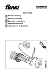
SeaSide
T07
ASSEMBLY INSTRUCTIONS
FR INSTRUCTIONS POUR LE MONTAGE
DE MONTAGE-ANWEISUNGEN
EN
The assembly instructions will be
found, together with IMPORTANT
precautionary notes, toward the end of
the manual.
FR Les
AVERTISSEMENTS
et
les
explications des phases de montage se
trouvent à la fin du manuel.
DE Die HINWEISE und die Beschreibung
der Montageschritte befinden sich am
Ende dieser Anleitung.
EN
EN
FR
DE
SYMBOLS
SYMBOLES UTILISÉS
BILDZEICHEN
Electrical connections
Branchements électriques
Stromanschlüsse
Plumbing connections
Raccordements hydrauliques
Wasseranschlüsse
Caution
Attention
Achtung
Article T07
Article T07
Artikel T07
Net weight
Poids net
Nettogewicht
Water capacity
Contenance eau
Wasserinhalt
155 kg
680 lt
(1)
Floor load
Charge au sol
Bodenbelast
Shipping weight
Poids emballage compris
Versandgewicht
Shipping volume
Cubage
Versandvolumen
Flow rate
Débit
Durchfluss
260 kg/m2
275 kg
3,2 m3
280 l/min
(1) - At overflow level • Au niveau du trop-plein • Bis zum Überlauf
ELECTRICAL SPECIFICATIONS (2)
CaraCteristiQUES ELECTRIQUES (2)
ELEKTRISCHE DATEN (2)
Model
Modèle
Modell
2WLK28
V
240
Hz
Rated power
Puissance installée
Installierte Leistung
50
2 Kw
(2) - Before making any electrical connections, check that the rated voltage and current of the appliance are matched to the mains power supply.
(2) - Avant de raccorder l’hydrodouche, s’assurer que les données de la plaquette correspondent aux données du réseau de distribution électrique.
(2) - Überprüfen Sie vor dem Stromanschluß die Entsprechung von Schild- und Netzwerten.
2
1
21
50
00
20
>2
~ 660
> 400
551+0
-10
> 38
00
2065 +5
-0
0
150 80
190 200
1940+5
-0
28
34
+5 3
-
Ø40
380
150 150
Ø40
740
97
150 200
1300
160
Ø40
2150
120
800
1367
257
~
660
930
120
A-A
498
+0
A
551 -10
1750
A
1265
2000
1000
526
INSPECTION
SIDE
LATO ISPEZIONABILE
CÔTÉ RÉSERVÉ À L'INSPECTION
INSPIZIERBARE SEITE
3
2
+5
206
0 -0
5 -+05
> 400
551 +0
-10
4
19
>2
00
0
2065 +5
-0
1032.5
970
1940 +5
-0
28
34
+
-3 5
970
1032.5
INSPECTION SIDE
CÔTÉ RÉSERVÉ À L'INSPECTION
INSPIZIERBARE SEITE
4
3
x16
80
M6x10
210
19
7
x4
nr3
210
7
80
19
4
5
5
1
2
x4
Ø6-S8
6
1
2
3
=
=
4
x2
6
7
=
--
=
--
--
=
--
=
8
7
9
10
IPX5
PG13,5
L
N
PG9
N
8
L
11
> 38
12
1
2
9
13
OK
MIN. 5 mm
NO
10
Assembly instructions Article T07-SeaSide
EN
IMPORTANT
The product must be installed exactly as supplied by Teuco, otherwise warranty will be invalidated. The directions for installation
must be observed to the letter, as must those concerning recommended materials and the accessories supplied with the product.
Electrical connections must be carried out in compliance with safety regulations governing bathroom
installations as described in the enclosed INSTALLATION REGULATIONS manual.
This manual constitutes an integral part of the product and must be kept for future reference.
HANDLING THE BATHTUB:
When removing the bathtub from its packing and throughout handling operations, lift by the rim or the frame.
CHECKS:
Having removed the bathtub from the packing, inspect for possible defects.
DAMAGE CAUSED BY IMPACT OR ABRASION IS NO LONGER COVERED BY WARRANTY ONCE THE TUB HAS BEEN INSTALLED.
Make certain that plumbing and electrical connections are made as indicated in the PREINSTALLATION instructions (STEP 1).
The tub must be installed with floor and walls already finished.
All Teuco products are tested, inspected and packed before leaving the factory. When unpacked, the tub may contain traces
of water from factory testing; before proceeding with final installation and completing masonry works, if any, run a further test
as described under "TESTING THE BATHTUB" to make doubly certain that the product functions exactly as it should.
If faults or substandard operation of the system are discovered, contact a Teuco technician or approved service centre.
The company will acknowledge no liability for damage to appliances that have been tampered with.
Data and specifications indicated in the manual are not binding on the company: Teuco Guzzini SpA reserves the
right to make such changes as are deemed appropriate without notice or obligation to update.
1 -PREINSTALLATION art T07-SeaSide
- Hot water tap connection 1/2"
- Cold water tap connection 1/2"
- IPX5 box with PG13.5 and PG9 cable clamps
- Electrical connection
-Alarm system connection
2 -PREPARING THE BUILT-IN ENCLOSURE
When preparing the enclosure and panel, keep to
the measurements indicated in the drawing.
A full-length removable panel must be provided
along the side of the tub (as illustrated), allowing
inspection and ventilation of the system; the panel
must be secured semi-permanently (with screws, for
example) in such a way that a tool is needed to
remove it, as prescribed by safety standards.
FITTING THE ALUMINIUM SECTIONS
3 -Join the aluminium sections together with the plates
and threaded studs supplied by Teuco.
Be sure to observe the measurements indicated
when positioning the sections.
4 -Apply the sections to the edge of the enclosure with
NEUTRAL (Non Acetic) silicone sealant.
5 -Secure the profiles on the edge of the recess using
screws with stops (not provided) ON TWO
ADJACENT SIDES ONLY.
ASSEMBLE THE LED
6 -Assemble the LED strips as illustrated in the figures.
7 -IInsert the springs supplied, taking care that they do
not meet with the LEDs
8 -Connect the “super seal” terminals to the transformer.
9 -PLUMBING CONNECTIONS
Rest the tub on the enclosure wall so that plumbing
and electrical connections can be made.
Connect the taps to the hot water supply ( ) and to
the cold water supply ( ).
Connect the waste to the drain using the trap provided.
10 -ELECTRICAL CONNECTIONS
Before making any electrical connections, check that
the rated voltage and current of the appliance (see
data plate) are matched to the mains power supply.
- IPX5 box with PG13.5 and PG9 cable clamps
- Electrical connection
-Alarm system connection
Connect the alarm
- only if the bathroom is
equipped with an alarm system.
EQUIPOTENTIAL EARTH CONNECTION
Use terminal S for the connection of any external
wires that need to be equipotentially bonded.
11 - LEVELLING THE TUB
Position the tub correctly in the enclosure, being
careful not to disturb the waste connection.
Level up the tub, first by adjusting the outermost feet,
then bringing the middle feet into contact with the floor.
Make the adjustment so as to leave a clearance of
38 mm minimum between the rim of the tub and the
surround wall.
TESTING THE BATHTUB
1) Clean any dirt from the tub
2) Fill the tub up to the level of the overflow
3)Start up the system (see user manual), then proceed
to check that there are no leaks, and no error
messages displayed on the control panel
4) Having run the test, complete the installation.
12 - ASSEMBLY OF OPALINI PROFILES
Assemble the Opalini profiles onto the aluminium
profiles using NEUTRAL silicone (non-acetic).
11
Instructions pour le Montage Article T07-SeaSide
FR
AVERTISSEMENTS
Pour jouir de la garantie, la minipiscine doit être installée telle qu'elle est fournie par Teuco.
Respecter les instructions de montage, les outils et le matériel conseillés ainsi que les
Procéder à l'installation électrique conformément aux consignes de sécurité pour l'installation dans les salles de
bains en suivant les explications du manuel en annexe CONSIGNES POUR L'INSTALLATION.
Ce manuel doit toujours accompagner l'appareil. Le conserver pour toute consultation future.
MANUTENTION DE LA BAIGNOIRE :
Pour retirer la baignoire de son emballage et durant la manutention, la soulever par le bord ou par le châssis.
CONTRÔLES :
Après avoir retiré la baignoire de son emballage, contrôler éventuellement si elle présente des défauts.
APRÈS L'INSTALLATION, LA GARANTIE NE RÉPOND PLUS DES DOMMAGES PROVOQUÉS PAR LES CHOCS OU LES ABRASIONS.
Vérifier que les raccordements hydrauliques et électriques prédisposés correspondent à ceux qui sont indiqués pour
la PRÉINSTALLATION (PHASE 1).
Installer la baignoire après avoir posé le revêtement du sol et fini les parois.
Tous nos produits sont testés, contrôlés et emballés dans notre usine. La présence éventuelle d'eau à l'intérieur de
la baignoire est due à la phase de test; avant de procéder à l'installation définitive de la baignoire qui pourrait prévoir
des ouvrages de maçonnerie, faire un test supplémentaire en suivant les explications de la phase “TEST DE LA
BAIGNOIRE”, pour vérifier si la baignoire fonctionne correctement.
En cas de panne ou de dysfonctionnement du circuit, s'adresser au personnel qualifié Teuco.
La société ne répond pas des dommages éventuels provoqués par des appareils manipulés de façon impropre.
Les données et les caractéristiques indiquées dans le manuel n'engagent pas Teuco Guzzini S.p.A. qui se réserve le
droit de modifier ses produits sans préavis ni remplacement.
1 -PRÉINSTALLATION art T07-SeaSide
- Raccordement eau chaude pour robinetterie 1/2"
- Raccordement eau froide pour robinetterie 1/2"
- Boîtier IPX5 avec serre-câbles PG13,5 et PG9
- Raccordement alimentation électrique
- Branchement du système d'alarme
2 -PRÉPARATION DU CAISSON
D'ENCASTREMENT
Pour réaliser le caisson dans lequel la minipiscine
sera encastrée et le panneau amovible, respecter
les mesures indiquées sur le dessin.
Il est obligatoire de réaliser un panneau amovible sur
le côté de la baignoire (comme le montre la figure)
pour permettre l'inspection et la ventilation du circuit;
le panneau devra être fixé (par exemple avec des vis)
de sorte qu'il soit nécessaire d'utiliser des outils pour
le démonter, comme l'exige la norme de sécurité.
MONTAGE
DES PROFILÉS EN
ALUMINIUM
3 -Fixer les profilés en aluminium entre eux à l'aide de
4
5
plaquettes et de goujons filetés fournis par Teuco.
Vérifier l'emplacement des profilés en fonction des
mesures indiquées.
-Monter les profilés sur le bord du caisson et poser un
mastic silicone NEUTRE (sans acétate).
-Fixer
les profils sur le bord de l'encaissement avec
les vis à cran d'arrêt (non fournies) SEULEMENT
SUR DEUX COTES CONTIGUS.
aux raccordements hydrauliques et électriques.
Raccorder la robinetterie au réseau d'alimentation
en eau chaude ( ) et froide ( ).
Procéder au raccordement du conduit d'évacuation
en installant le siphon fourni.
10 -CONNEXIONS ÉLECTRIQUES
Avant de procéder au raccordement, s'assurer que
les caractéristiques électriques de l'appareil (voir
données sur la plaquette) correspondent à celles du
réseau de distribution électrique.
- Boîtier IPX5 avec serre-câbles PG13,5 et PG9
- Raccordement alimentation électrique
- Branchement du système d'alarme
Brancher le câble d'alarme
- uniquement si la
salle de bains est dotée du système d'alarme.
BRANCHEMENT ÉQUIPOTENTIEL
Utiliser la borne S pour la connexion d'éventuels
conducteurs externes destinés au branchement
équipotentiel supplémentaire.
11 - MISE À NIVEAU
Placer la baignoire à l'endroit choisi en faisant
attention au raccordement du conduit d'évacuation.
Mettre la baignoire de niveau en réglant d'abord les
pieds extérieurs puis les pieds centraux jusqu'à ce qu'ils
entrent en contact avec le sol.
Procéder à ce réglage de sorte qu'il reste au moins
38 mm entre le bord de la baignoire et le mur d'appui.
TEST DE LA BAIGNOIRE
7 -IIntroduire les ressorts fournis en faisant attention à ne
1) Nettoyer la baignoire pour éliminer toute trace de saleté
2) Remplir la baignoire jusqu'au trop-plein de la colonne
de vidage
3)Mettre le circuit en marche (voir manuel d’utilisation)
pour vérifier s'il y a des fuites d'eau ou la signalisation
de pannes sur le panneau de commande
4) Après le test, terminer l'installation.
8 -Brancher les deux terminaux “super seal” au transformateur
12 -MONTAGE DES PROFILS OPALINS
ASSEMBLER LES BANDEAUX DE DIODES
6 -Assembler
les
bandeaux
de
diodes
électroluminescentes en suivant les images.
pas les faire coïncider avec la diode électroluminescente
9 -RACCORDEMENTS HYDRAULIQUES
Placer la baignoire sur le bord du caisson pour procéder
12
Monter les profils opalins sur les profils en aluminium avec du
silicone NEUTRE (non acétique)
Montageanleitungen Artikel T07-SeaSide
DE
HINWEISE
Zur Gültigkeit der Garantie muss das Produkt wie von Teuco geliefert installiert werden. Achten Sie auf die
Montageanleitungen, die Werkzeuge sowie die Materialempfehlungen und die mit dem Produkt gelieferten Zubehörteile.
Bei der elektrischen Installation beachten Sie die Sicherheitsvorschriften für die Installation in Badezimmern
gemäß beiliegenden INSTALLATIONSANLEITUNGEN.
Bewahren Sie diese Anleitung sorgfältig auf, sie ist wesentlicher Bestandteil der Anlage und dient als Nachschlagewerk.
HANDHABUNG DES WHIRLPOOLS:
Fassen Sie den Whirlpool beim Auspacken und Handhaben am Rand bzw. Gestell an.
ÜBERPRÜFUNGEN:
Überprüfen Sie den Whirlpool nach dem Auspacken auf etwaige Mängel.
MIT DER INSTALLATION ERLISCHT DIE GARANTIE AUF SCHÄDEN DURCH STÖSSE ODER KRATZER.
Überprüfen Sie die Entsprechung der hergestellten Wasser- und Stromanschlüsse mit den Vorgaben der
VORINSTALLATION (SCHRITT 1).
Die Installation muss nach Fertigstellung des Boden- und Wandbelags erfolgen.
All unsere Produkte werden im Werk abgenommen, inspiziert und verpackt. Etwaige Wasserrückstände im Whirlpool
rühren von der Abnahmeprüfung her. Vor der endgültigen Installation des Whirlpools und den ggf. erforderlichen
baulichen Maßnahmen sollten Sie eine weitere Abnahme nach den Angaben im Arbeitsschritt “ABNAHMEPRÜFUNG
DES WHIRLPOOLS” durchführen und die einwandfreie Funktion des Produkts nachweisen.
Bei Betriebsstörungen der Anlage wenden Sie sich bitte ausschließlich an Teuco Fachpersonal.
Der Hersteller haftet nicht für Schäden, die auf unsachgemäß durchgeführte Wartungs- oder Reparaturarbeiten zurückzuführen sind.
Die in der Anleitung angegebenen Daten und Produkteigenschaften sind nicht verbindlich. Teuco Guzzini SpA behält sich das Recht vor,
ohne Vorankündigung alle für nötig erachteten Änderungen vorzunehmen, ohne dass sich hieraus Ersatzansprüche ableiten lassen.
1 -VORINSTALLATION Mod. T07-SeaSide
- Warmwasseranschluss für Armaturen 1/2"
- Kaltwasseranschluss für Armaturen 1/2"
- Kasten IPX5 mit Kabelklemmen PG13,5 und PG9
- Stromanschluss
-Anschluss Des Alarmsystems
2 -EINBAUVORBEREITUNG
Beachten Sie für Einbau und Paneel die in der
Zeichnung angegebenen Abmessungen.
Auf der Whirlpoolseite (s. Abbildung) müssen Sie ein
abnehmbares Paneel zur Inspektion und Belüftung
der Anlage anfertigen. Das Paneel ist auf sichere
Weise (z.B. mit Schrauben) zu befestigen, damit die
Abnahme nur anhand eines Werkzeugs erfolgen
kann, wie es die einschlägigen Normen vorschreiben.
MONTAGE DER ALUMINIUMPROFILE
3 -Befestigen Sie die Aluminiumprofile mit den von
Teuco gelieferten Platten und Gewindestiften
untereinander. Richten Sie die Profile nach den
angegebenen Maßen aus.
4 -Dichten Sie die am Einbaurand installierten Profile
mit NEUTRALEM (nicht essigsaurem) Silikon ab.
5 -Die Profile am Rand der Einbauöffnung mit den
(nicht mitgelierten) Bundschrauben NUR AN ZWEI
ANEINANDERGRENZEN SEITEN befestigen.
ASSEMBLE THE LED
6 -Assemble the LED strips as illustrated in the figures.
7 -IInsert the springs supplied, taking care that they do
not meet with the LEDs
8 -Connect the “super seal” terminals to the transformer.
9 -WASSERANSCHLÜSSE
Setzen Sie den Whirlpool am Einbaurand ab und
stellen Sie die Wasser-und Stromanschlüsse her.
Schließen Sie die Armaturen an die Warm- ( ) und
Kaltwasserleitung ( ) an.
Verwenden Sie zum Ablaufanschluss den
mitgelieferten Siphon.
10 -ELEKTRISCHEANSCHLÜSSE
Vergewissern Sie sich vor dem Stromanschluss des
Produkts, dass die elektrischen Eigenschaften (siehe
Typenschild) mit denen des Stromnetzes
übereinstimmen.
- Kasten IPX5 mit Kabelklemmen PG13,5 und PG9
- Stromanschluss
-Anschluss Des Alarmsystems
Verbinden Sie das Alarmkabel
- nur bei
Badezimmern mit Alarmsystem.
POTENTIALAUSGLEICHANSCHLUSS
An die Klemme S können Sie etwaige Außenleiter
für den zusätzlichen Potentialausgleich anschließen.
11 - AUSRICHTUNG
Setzen Sie den Whirlpool an dem eingerichteten
Standort ab und achten Sie hierbei auf den
Ablassanschluss. Richten Sie den Whirlpool zuerst
mit den Außenfüßen und dann mit den Mittelfüßen
auf Bodenkontakt aus. Belassen Sie bei der
Einstellung einen Mindestabstand von 38 mm
zwischen Whirlpoolrand und Aufnahmemauer.
ABNAHMEPRÜFUNG DES WHIRLPOOLS
1) Reinigen Sie den Whirlpool von Schmutzresten
2) Füllen Sie den Whirlpool bis zum Überlauf der
Ablaufgarnitur
3)Starten Sie die Anlage (siehe Bedienungsanleitung)
und überprüfen Sie, ob etwaige Wasseraustritte
bzw. Fehlermeldungen am Schaltdisplay vorliegen
4) Stellen Sie die Installation nach der Abnahmeprüfung fertig.
12 - MONTAGE DER OPALGLASPROFILE
Die Opalglasprofile mithilfe von NEUTRALEM (nicht
essigsaurem) Silikon an den Aluminiumprofilen
anbringen.
13
14
15
Teuco Guzzini S.p.A.
Via Virgilio Guzzini, 2 - 62010 Montelupone (MC) – Italy
T. 0039-0733-2201 - F. 0039-0733-220391
www.teuco.it - [email protected]
Numero Verde 800-270270
United Kingdom: Teuco UK Ltd
160 City Road - London - EC1V 2NP
T. 0044-(0)-207-6083090 - F. 0044-(0)-207-6083089
www.teuco.com - [email protected]
France: Teuco France sarl
151 Avenue du Maine - 75014 Paris
T. 033-1-58142070 - 033-1-45452260
www.teuco.fr - [email protected]
67100743600 (2011.00)
España:Teuco España s.l.
C/ Granada, 45 - 08740 Sant Andreu de la Barca - Barcelona
T. 0034-902-8898.03 - F. 0034-902-8898.04
www.teuco.es - [email protected]
Russia: “TEUCO 000”
Via Bolshaja Cherkizovskaja, 24ª - 107553 Moscow
T. 007-495-5140704 - F. 007-495-5648274
www.teuco.ru - [email protected]
E-mail: [email protected] - Internet: http://www.teuco.com