1
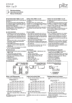
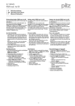
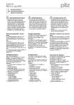
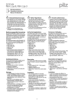
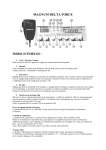
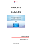
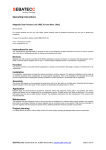
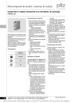
22 147-01
PSEN ma1.3p-20
4
4
4
D
Betriebsanleitung
GB Operating instructions
F
Manuel d'utilisation
22 147-01
PSEN
ma1.3p-20
Sicherheitsschalter PSEN ma1.3p-20
Safety switch PSEN ma1.3p-20
Capteur de sécurité PSEN ma1.3p-20
833339787
Der Sicherheitsschalter erfüllt Forderungen der
EN 60204-1.
Der Sicherheitsschalter erfüllt EN 60947-5-3
nur zusammen mit dem Betätiger PSEN
ma1.3-08 oder PSEN ma1.3-12 und hierfür zugelassenen Auswertegeräten.
Schließen Sie den Sicherheitsschalter nur an
Auswertegeräte an, die im Abschnitt "Anschlüsse" aufgeführt sind.
The safety switch meets the requirements of
EN 60204-1.
The safety switch only complies with
EN 60947-5-3 in conjunction with the actuator
PSEN ma1.3-08 or PSEN ma1.3-12 and its approved evaluation devices.
The safety switch should only be connected to
the evaluation devices listed under "Connections".
Le capteur de sécurité satisfait aux exigences
de l'EN 60204-1.
Le capteur de sécurité est conforme à la norme
EN 60947-5-3 uniquement lorsqu'il est utilisé
avec l'actionneur PSEN ma1.3-08 ou
PSEN ma1.3-12 et les unités de contrôle spécialement homologuées.
Ne raccordez le capteur de sécurité qu'aux unités de contrôle indiquées dans le chapitre
« Raccordements ».
Zu ihrer Sicherheit
` Installieren und nehmen Sie das Gerät nur
For your safety
` Only install and commission the unit if you
Pour votre sécurité
` Vous n'installerez l'appareil et ne le mettrez
547263243
dann in Betrieb, wenn Sie diese Betriebsanhave read and understood these operating
en service qu'après avoir lu et compris le
leitung gelesen und verstanden haben und
instructions and are familiar with the applica- présent manuel d'utilisation et vous être faSie mit den geltenden Vorschriften über Arble regulations for health and safety at work
miliarisé avec les prescriptions en vigueur
beitssicherheit und Unfallverhütung vertraut
and accident prevention.
sur la sécurité du travail et la prévention des
sind.
Ensure VDE and local regulations are met,
accidents.
Beachten Sie die VDE- sowie die örtlichen
especially those relating to safety.
Respectez les normes locales ou VDE, parti` Any guarantee is rendered invalid if the hous- culièrement en ce qui concerne la sécurité.
Vorschriften, insbesondere hinsichtlich
ing is opened or unauthorised modifications ` L'ouverture de l'appareil ou sa modification
Schutzmaßnahmen
annule automatiquement la garantie.
` Durch Öffnen des Gehäuses oder eigenare carried out.
mächtige Umbauten erlischt jegliche Gewährleistung.
Gerätemerkmale
Unit features
` Zum Sicherheitsschalter gehört der Betätiger ` The safety switch is used with the actuator
1091646731
`
`
`
`
PSEN ma1.3-08 oder PSEN ma1.3-12
Sicherheitsschalter mit M8/8-pol. Stecker
2 Sicherheitskontakte (Schließer)
1 Hilfskontakt (Schließer)
Betätiger PSEN ma1.3-08:
– Gesicherter Schaltabstand: 8 mm
– Gesicherter Ausschaltabstand: 15 mm
Betätiger PSEN ma1.3-12:
– Gesicherter Schaltabstand: 12 mm
– Gesicherter Ausschaltabstand: 25 mm
Sicherheitsschalter und Betätiger mit runder
Bauform M12
oder
Sicherheitsschalter mit runder Bauform M12,
Betätiger mit quadratischer Bauform (verschiedene Betätigungsrichtungen möglich)
Wirkweise magnetisch
Schaltspannung 24 V DC
LED zur Anzeige des Schaltzustands
1140433803
510237579
1091653387
1091670795
`
`
808101259
`
`
`
`
510321547
510477451
763865611
`
`
`
`
`
`
`
`
`
`
PSEN ma1.3-08 or PSEN ma1.3-12
Safety switch with M8/8-pin connector
2 safety contacts (N/O)
1 auxiliary contact (N/O)
Actuator PSEN ma1.3-08:
– Assured operating distance: 8 mm
– Assured release distance: 15 mm
Actuator PSEN ma1.3-12:
– Assured operating distance: 12 mm
– Assured release distance: 25 mm
Safety switch and actuator with M12 round
design
or
Safety switch with M12 round design, actuator with square design (various directions of
actuation are possible)
Works magnetically
Switching voltage 24 VDC
LED to display switch status
Caractéristiques de l'appareil
` L'actionneur PSEN ma1.3-08 ou PSEN
`
`
`
`
`
`
`
`
`
`
ma1.3-12 est associé au capteur de sécurité.
Capteur de sécurité avec connecteur M8 à 8
broches
2 contacts de sécurité (contacts à fermeture)
1 contact d'information (contact à fermeture)
Actionneur PSEN ma1.3-08 :
– Distance de commutation
de sécurité : 8 mm
– Distance de déclenchement
de sécurité :15 mm
Actionneur PSEN ma1.3-12 :
– Distance de commutation
de sécurité : 12 mm
– Distance de déclenchement
de sécurité : 25 mm
Capteurs de sécurité et actionneurs avec
une architecture arrondie M12
ou
Capteurs de sécurité avec une architecture
arrondie M12, actionneurs avec architecture
carrée (différents sens de manœuvre possibles)
actionnement magnétique
tension commutée 24 V DC
LED pour l'affichage de l'état de commutation
Schaltabstände
Operating distances
Distances de commutation
Betätiger PSEN ma1.3-08
Actuator PSEN ma1.3-08
Actionneur PSEN ma1.3-08
Seitenversatz/Lateral offset/
Décalage latéral
Höhenversatz/Height offset/
Décalage en hauteur
sar = 15
sao = 8
Ansprechfläche/Sensing face/Surface d'activation
-1-
Schaltabstand/
Operating distance/
Portee de travail
Ein/On/Marche
Aus/Off/Arrêt
Betätiger PSEN ma1.3-12
Actuator PSEN ma1.3-12
Seitenversatz/Lateral offset/
Décalage latéral
Actionneur PSEN ma1.3-12
Höhenversatz/Height offset/
Décalage en hauteur
Schaltabstand/
Operating distance/
Portee de travail
sar = 25
sao = 12
Ansprechfläche/Sensing face/Surface d'activation
Ein/On/Marche
Aus/Off/Arrêt
Lateral and vertical offset
Décalage latéral et en hauteur
Betätiger PSEN ma1.3-08
` Gesicherter Schaltabstand Sao in mm:
Actuator PSEN ma1.3-08
` Assured operating distance Sao in mm:
Actionneur PSEN ma1.3-08
` Distance de commutation de sécurité Sao en
mm :
2
4
0
8,0
7,0
5,5
2
7,0
6,0
4,0
4
6,0
5,0
3,0
` Gesicherter Ausschaltabstand Sar:
Max. 15 mm bei allen Höhen- und Seitenversätzen
Betätiger PSEN ma1.3-12
` Gesicherter Schaltabstand Sao in mm:
1044323979
Seitenversatz/Lateral
offset/Décalage latéral
Höhenversatz/Height offset/
Décalage en hauteur
0
1
2
0
12,0 10,0 8,0
2
12,0 10,0 8,0
4
11,0 9,5
7,5
6
10,0 8,5
6,5
` Gesicherter Ausschaltabstand Sar:
Max. 25 mm bei allen Höhen- und Seitenversätzen
` Negativer Höhenversatz nicht zugelassen
Die angegebenen Werte sind gültig bei einer
Temperatur von 20°C.
Höhenversatz negativ/positiv
0
2
4
0
8,0
7,0
5,5
2
7,0
6,0
4,0
4
6,0
5,0
3,0
Seitenversatz/Lateral
offset/Décalage latéral
0
Höhenversatz/Height offset/
Décalage en hauteur
` Assured release distance Sar:
Höhenversatz/Height offset/
Décalage en hauteur
0
2
4
0
8,0
7,0
5,5
2
7,0
6,0
4,0
4
6,0
5,0
3,0
Max. 15 mm with all vertical and lateral off- ` Distance de coupure de sécurité Sar :
15 mm maximum pour tous les décalages
sets
latéraux et en hauteur
Actuator PSEN ma1.3-12
Actionneur PSEN ma1.3-12
` Assured operating distance Sao in mm:
` Distance de commutation de sécurité Sao en
mm :
Höhenversatz/Height offset/
Décalage en hauteur
0
1
Höhenversatz/Height offset/
Décalage en hauteur
2
0
12,0 10,0 8,0
2
12,0 10,0 8,0
4
11,0 9,5
7,5
6
10,0 8,5
6,5
Seitenversatz/Lateral
offset/Décalage latéral
Höhenversatz/Height offset/
Décalage en hauteur
Seitenversatz/Lateral
offset/Décalage latéral
Seitenversatz/Lateral
offset/Décalage latéral
803367563
Seitenversatz/Lateral
offset/Décalage latéral
Seiten- und Höhenversatz
` Assured release distance Sar:
0
1
2
0
12,0 10,0 8,0
2
12,0 10,0 8,0
4
11,0 9,5
7,5
6
10,0 8,5
6,5
Max. 25 mm with all vertical and lateral off- ` Distance de coupure de sécurité Sar :
25 mm maximum pour tous les décalages
sets
latéraux et en hauteur
` A negative vertical offset is not permitted
` Le décalage négatif en hauteur n'est pas
autorisé
The stated values are valid at a temperature of
20°C.
Les valeurs indiquées sont valables pour une
température de 20 °C.
Negative/positive vertical offset
Décalage en hauteur négatif / positif
+
-2
-1
0
-2-
1
2
Verdrahtung
Wiring
Câblage
Beachten Sie:
Please note:
Important :
` Angaben im Abschnitt „Technische Daten“ ` Information given in the “Technical details” ` Tenez compte impérativement des données
unbedingt einhalten.
must be followed.
indiquées au chapitre "Caractéristiques
` Berechnung der max. Leitungslänge Imax im ` Calculation of the max. cable runs lmax in the techniques".
` Calcul de la longueur de câble max. Imax sur
Eingangskreis:
input circuit:
le circuit d'entrée :
Rlmax
Rlmax
Imax =
Imax =
Rlmax
Rl / km
Rl / km
Imax =
Rl / km
Rlmax = max. Gesamtleitungswiderstand
Rlmax = max. overall cable resistance (see
Rlmax = résistance max. de l'ensemble du
(s. techn. Daten)
Technical details)
câblage (voir les caractéristiques techniRl / km = Leitungswiderstand/km
Rl / km = cable resistance/km
ques)
` Beachten Sie bei Einsatz von Auswertegerä- ` When using evaluation devices with delay-on
Rl /km = résistance du câblage/km
ten mit rückfallverzögerten Kontakten:
de-energisation contacts, please note:
– Verzögerungszeit ≤30 s: die rückfallverzö– Delay time ≤30 s: Delay-on de-energisation ` En cas de mise en œuvre d'appareils de congerten Kontakte genügen den Anforderuncontacts satisfy the requirements of catetrôle avec contacts temporisés à la retomgen der Kategorie 3 gemäß EN 954-1 bzw.
gory 3 in accordance with EN 954-1 and
bée, il faut tenir compte des indications
den Anforderungen an PDF mit Einfehlersithe requirements of a PDF with single-fault
suivantes :
cherheit (PDF-S).
tolerance (PDF-S).
– Temporisation ≤30 s : les contacts tempo– Verzögerungszeit ≥ 30 s: die rückfallverzö- – Delay time ≥ 30 s: Delay-on de-energisarisés à la retombée satisfont aux prescripgerten Kontakte genügen den Anforderuntion contacts satisfy the requirements of
tions de la catégorie 3 selon l'EN 954-1, et/
gen der Kategorie 1 gemäß EN 954-1 bzw.
Category 1 in accordance with EN 954-1
ou aux prescriptions des PDF avec sécuriden Anforderungen an PDF mit Zuverläsand the requirements of a PDF with deté de défaut unique (PDF-S).
sigkeit durch besonderes Design (PDF-D).
signed reliability (PDF-D).
– Temporisation ≥ 30 s : les contacts tempo` Überprüfen Sie in folgenden Fällen von Inbe- ` In the following commissioning cases, check
risés à la retombée satisfont aux prescriptriebnahme die Funktion Querschlusserkenthe function that detects shorts across contions de la catégorie 1 selon l'EN 954-1, et/
nung:
tacts:
ou aux prescriptions des PDF avec une
– Bei Auswertegeräten mit Versorgungs– On evaluation devices with DC supply
fiabilité obtenue grâce à un design particuspannung DC: Gesamtleitungswiderstand
voltage: Overall cable resistance ≥ 15
lier (PDF-D).
≥ 15 Ohm pro Kanal
Ohms per channel
` Vérifiez dans les cas suivants de mise en ser– Bei Auswertegeräten mit Versorgungs– On evaluation devices with AC supply volt- vice la fonction de détection des courtsspannung AC: Gesamtleitungswiderstand
age: Overall cable resistance ≥ 25 Ohms
circuits :
≥ 25 Ohm pro Kanal
per channel
– pour les appareils de contrôle avec ali– Wie Sie die Querschlussprüfung durchfüh- – For details of how to perform the test for
mentation DC : Résistance de l'ensemble
ren müssen, entnehmen Sie der entspreshorts across the contacts, please refer to
du câblage ≥ 15 ohms par canal
chenden Bedienungsanleitung des
the operating manual for the relevant eval- – pour les appareils de contrôle avec aliAuswertegeräts.
uation device.
mentation AC : Résistance de l'ensemble
du câblage ≥ 25 ohms par canal
– vous trouverez dans la notice d'utilisation
de l'appareil de contrôle comment exécuter le contrôle des courts-circuits.
492354955
Anschlüsse
Connections
Raccordements
Anschlussbelegung
Pin assignment
Affectation des bornes
WICHTIG
NOTICE
IMPORTANT
Die Farbkennzeichnung für die AnschlusThe colour marking for the connection lead
Le marquage de couleur du câble de racsleitung gilt nur für die als Zubehör erhältlionly applies for the cable that Pilz supplies
cordement est uniquement valable pour les
chen Kabel von Pilz.
as an accessory.
câbles Pilz disponibles en tant qu'accesDer Sicherheitsschalter ist in unbetätigtem Zu- The safety switch is shown in an unoperated
soires.
stand dargestellt.
condition.
Le capteur de sécurité est représenté en position de repos.
777658251
Belegung des 8-pol. M8-Stiftsteckers/Assignment of the 8-pin M8 male connector/Repérage du connecteur mâle M8 à 8 pôles
6
3
5
6
4
8
7
1
3
2
1
4
2+
5
807945483
WICHTIG
Der Hilfskontakt mit LED
` darf mit PNOZ X-Geräten nur mit Versorgungsspannung bis 24 V DC betrieben
werden
` ist mit PNOZ X-, PNOZelog- und
PNOZmulti-Geräten nicht in Reihe
schaltbar
NOTICE
The auxiliary contact with LED
` May only be operated with a supply voltage up to 24 VDC on PNOZ X units
` May not be connected in series with
PNOZ X, PNOZelog and PNOZmulti
units
-3-
grün/green/vert
weiß/white/blanc
gelb/yellow/ambre
braun/brown/marron
blau/blue/bleu
7
8
rosa/pink/rose
grau/grey/gris
rot/red/rouge
NC
NC
IMPORTANT
Le contact d'information avec LED
` ne doit être utilisé, pour les appareils
PNOZ X, qu'avec une alimentation jusqu'à 24 V DC
` ne peut pas être monté en série avec les
appareils PNOZ X, PNOZelog et
PNOZmulti
Anschluss an Auswertegeräte
Der Hilfskontakt mit LED kann als Meldeausgang verwendet werden (siehe technische Daten)
` Anschluss Hilfskontakt mit LED
785477899
Connection to evaluation devices
Raccordement aux appareils de contrôle
The auxiliary contact with LED may be used as Le contact d'information avec LED peut être
a signal output (see Technical details)
utilisé comme sortie d'information (voir les caractéristiques techniques)
` Auxiliary contact with LED connection
` Raccordement du contact d'information
avec LED
PNOZ X, PNOZpower, PNOZsigma, PNOZelog
A1/+24 V
braun/brown/marron
GND
blau/blue/bleu
PNOZmulti, PSS, PSSu
1
A1/+24 V
2
braun/brown/marron
1
2
3
3
4
4
5
5
6
I7
7
blau/blue/bleu
6
7
8
8
` Anschluss an PNOZ, PNOZ X, PNOZpower, ` Connection to PNOZ, PNOZ X, PNOZpower, ` Raccordement aux PNOZ, PNOZ X,
PNOZsigma, PNOZelog
PNOZ p1p
PNOZ p1vp
PNOZ X2/X2P
PNOZ X2.1
(nur 24 V DC/
24 V DC only/
24 V DC seulement)
PNOZ X2.3P
PNOZ X2.7P
PNOZ X2.8P
PNOZsigma, PNOZelog
PNOZ X2C
PNOZ X2.1C
(nur 24 V DC/
24 V DC only/
24 V DC seulement)
PNOZ X4/X8P
PNOZ X9
PNOZ X10/X10.1
PNOZ X10.11
PNOZ Ex
PNOZpower, PNOZsigma, PNOZelog
S21
PNOZ e1p
PNOZ e1.1p
PNOZ e1vp
PNOZ e6.1p
PNOZ e6vp
PNOZ s3
PNOZ s4
PNOZ s5
weiß/white/blanc
1
2
S22
gelb/yellow/jaune
3
4
5
S11
S12
S11
rosa/pink/rose
grün/green/vert
weiß/white/blanc
6
7
8
1
2
S52
PNOZ X2.9P
gelb/yellow/jaune
3
4
5
S11
S12
S11
rosa/pink/rose
grün/green/vert
weiß/white/blanc
6
7
8
1
2
S22
PNOZ X5
PNOZ X5J
gelb/yellow/jaune
3
4
5
S11
S12
S21
rosa/pink/rose
grün/green/vert
weiß/white/blanc
6
7
8
1
2
PNOZ 11
PNOZ 16
PNOZ X11P
PNOZ X13
PNOZ X3.1
PNOZ X3P
PNOZ X2.5P
PNOZ X3
PNOZ X3.10P
PNOZ XV2
PNOZ XV2P
PNOZ XV3
PNOZ XV3P
S22
gelb/yellow/jaune
3
4
5
S31
S32
-4-
rosa/pink/rose
grün/green/vert
6
7
8
S23
weiß/white/blanc
1
2
S24
PNOZ X6 (mit Brücke/with link/avec pontage Y3-Y4)
gelb/yellow/jaune
3
4
5
S11
S12
S61
rosa/pink/rose
grün/green/vert
weiß/white/blanc
6
7
8
1
2
S62
PMUT X1P
gelb/yellow/jaune
3
4
5
S51
S52
A1
rosa/pink/rose
grün/green/vert
weiß/white/blanc
6
7
8
1
2
S32
PNOZ e5.11p
gelb/yellow/jaune
3
4
5
A1
S42
` Anschluss an PNOZmulti und PSS
` Connection to PNOZmulti and PSS
rosa/pink/rose
grün/green/vert
6
7
8
` Raccordement au PNOZmulti et au PSS
T0
weiß/white/blanc
1
2
Schutztür/safety gate/protecteur mobile
Schaltertyp 3/switchtype 3/type du capteure 3
I0, I1: Eingänge/inputs/entrées
T0, T1: Taktausgänge/test pulse outputs/sorties
impulsionelles
I0
gelb/yellow/jaune
3
4
5
T1
I1
-5-
rosa/pink/rose
grün/green/vert
6
7
8
Montage
Installation
Montage
` Berücksichtigen Sie bei der Montage die An- ` When installing make sure you comply with ` Veuillez tenir compte lors du montage des
796864011
forderungen der DIN EN 1088
the requirements of DIN EN 1088
exigences de la normes DIN EN 1088.
` Sicherheitsschalter und Betätiger möglichst ` If possible, do not install the safety switch
` Evitez d'installer le capteur de sécurité et
nicht auf ferromagnetisches Material montieren. Es sind Änderungen der Schaltabstände
zu erwarten.
` Der Abstand zwischen zwei Systemen aus
Sicherheitschalter und Betätiger muss bei
– Betätiger PSEN ma1.3-08
mindestens 25 mm betragen und
– Betätiger PSEN ma1.3-12
mindestens 35 mm betragen.
` Sicherheitsschalter und Betätiger
– von Eisenspänen fernhalten
– keinen starken Magnetfeldern aussetzen
– keinen starken Stößen oder Schwingungen aussetzen
– nicht als Anschlag benutzen
– nur für feste Verkabelung
Montage mit Betätiger PSEN ma1.3-08:
` Die Montagelage ist beliebig. Sicherheitsschalter und Betätiger müssen so montiert
werden, dass die abgeschrägten Flächen genau gegenüberliegen.
` Befestigen Sie Sicherheitsschalter und Betätiger ausschließlich mit Muttern M12 aus
nicht magnetischem Material (z. B. Messing).
Anzugsdrehmoment max. 300 Ncm.
Montage mit Betätiger PSEN ma1.3-12:
` Befestigen Sie den Betätiger mit dem mitgelieferten Halter. Die Ansprechfläche am Betätiger ist durch einen Kreis mit abgeschrägter
Fläche in Form des Sicherheitsschalters gekennzeichnet.
Die Ansprechfläche kann je nach Betätigungsrichtung in 3 Richtungen ausgerichtet
werden.
l'actionneur sur du matériel ferromagnétique.
Les distances de commutation peuvent être
modifiées.
` La distance entre deux systèmes composés
d'un capteur de sécurité et d'un actionneur
doit être
– pour l'actionneur PSEN ma1.3-08
d'au moins 25 mm et
– pour l'actionneur PSEN ma1.3-12
d'au moins 35 mm.
` Le capteur de sécurité et l'actionneur
– doivent être éloignés des copeaux métalliques
– ne doivent pas être exposés à des champs
magnétiques élevés
– ne doivent pas subir des chocs et vibrations importants
– ne doivent pas être utilisés comme butée
– ne doivent être utilisés que dans un câblage fixe
Montage avec l'actionneur PSEN ma1.3-08 :
` Le sens de montage n'a pas d'importance.
Cependant, le capteur de sécurité et l'actionneur doivent être montés de telle manière
que les surfaces biseautées soient exactement en face l'une de l'autre.
` Fixez le capteur de sécurité et l'actionneur
exclusivement à l'aide d'un écrou M12 dans
des matériaux non magnétiques (par
exemple : en laiton). Couple de serrage max.
300 Ncm.
Montage avec l'actionneur PSEN ma1.3-12 :
` Fixez l'actionneur à l'aide du support fourni à
la livraison. La surface d'activation sur l'actionneur est marquée par un cercle à la surface biseautée, dans la forme du capteur de
sécurité.
Suivant le sens de manœuvre, la surface
d'activation peut être orientée dans 3 directions différentes.
Ansprechfläche
Sensing face
Surface activation
and actuator on to ferromagnetic material.
Changes to the operating distances are to be
expected.
` The distance between two systems comprising safety switch and actuator must be
– At least 25 mm on the actuator
PSEN ma1.3-08
and
– At least 35 mm on the actuator
PSEN ma1.3-12
` Safety switches and actuators
– Should be kept away from iron swarf
– Should not be exposed to strong magnetic
fields
– Should not be exposed to heavy shock or
vibration
– Should not be used as a limit stop
– Should be used for fixed wiring only
Installation with actuator PSEN ma1.3-08:
` The unit can be installed in any position. The
safety switch and actuator must be installed
so that the bevelled surfaces face each other
precisely.
` The safety switch and actuator should only
be secured using M12 nuts made of nonmagnetic material (e.g. brass). Torque setting max. 300 Ncm.
Installation with actuator PSEN ma1.3-12:
` Attach the actuator using the bracket supplied. The sensing face on the actuator is
marked by a circle with a bevelled surface in
the shape of the safety switch.
The sensing face can be aligned in 3 directions, depending on the direction of actuation.
Ansprechfläche
Sensing face
Surface activation
Ansprechfläche
Sensing face
Surface activation
` Die Montagelage ist beliebig. Sicherheits-
schalter und Betätiger müssen so montiert ` The unit can be installed in any position.
Safety switches and actuators must be inwerden, dass die abgeschrägte Fläche des
stalled so that the bevelled surface on the
Sicherheitsschalters der aufgedruckten absafety switch and the embossed bevelled
geschrägten Fläche am Betätiger genau gesurface on the actuator face each other pregenüberliegt.
cisely.
` Befestigen Sie den Halter ausschließlich mit
` Le sens de montage n'a pas d'importance.
Schrauben aus nicht magnetischem Materi- ` The bracket should only be secured using
Cependant, le capteur de sécurité et l'actionscrews made of non-magnetic material.
al.
neur doivent être montés de telle manière
` Schieben Sie den Betätiger in der gewünsch- ` Slide the actuator on to the bracket in the re- que la surface biseautée du capteur de sécurité soient exactement en face de la surface
ten Betätigungsrichtung in den Halter ein, bis
quired direction of actuation until the actuabiseautée imprimée de l'actionneur.
der Betätiger einrastet. Befestigen Sie den
tor clicks into place. The actuator should be
Betätiger mit einer Madenschraube M3 x 6
secured using a set screw M3 x 6 mm: DIN ` Le support doit uniquement être fixé à l'aide
de vis en matériau non magnétique.
mm: DIN 319 (im Lieferumfang enthalten).
319 (supplied with the unit). Torque setting
` Faites glisser l'actionneur dans le support
Anzugsdrehmoment max. 10 Ncm.
max. 10 Ncm.
suivant dans le sens de manœuvre souhaité
jusqu'à l'enclenchement de l'actionneur.
Fixez l'actionneur à l'aide d'une vis sans tête
M3 x 6 mm : DIN 319 (fournie à la livraison).
Couple de serrage max. 10 Ncm.
-6-
Justage
Adjustment
Ajustement
Der Sicherheitsschalter darf nur mit dem zugehörigen Betätiger PSEN ma1.3-08 oder
PSEN ma1.3-12 verwendet werden.
` Prüfen Sie die Funktion immer mit einem der
zugelassenen Auswertegeräte.
` Die angegebenen Schaltabstände (siehe
technische Daten) gelten nur, wenn Sicherheitsschalter und Betätiger parallel gegenüberliegend montiert sind. Andere
Anordnungen können zu abweichenden
Schaltabständen führen. Beachten Sie den
maximal zulässigen Seiten- und Höhenversatz (siehe "Schaltabstände" und "Max. Seiten- und Höhenversatz").
The safety switch may only be used with the
corresponding actuator PSEN ma1.3-08 or
PSEN ma1.3-12.
` Always test the function with one of the approved evaluation devices.
` The stated operating distances (see Technical details) only apply when the safety switch
and actuator are installed facing each other
in parallel. Operating distances may deviate
if other arrangements are used. Note the
maximum permitted lateral and vertical offset (see "Switching distances" and "Max. lateral and vertical offset").
Le capteur de sécurité doit être utilisé uniquement avec l'actionneur correspondant
PSEN ma1.3-08 ou PSEN ma1.3-12.
` Vérifiez la fonction uniquement avec l'un des
appareils de contrôle homologués.
` Les distances de commutation mentionnées
dans les caractéristiques techniques sont
valables uniquement lorsque le capteur de
sécurité et l'actionneur sont montés l'un en
face de l'autre de manière parallèle. D'autres
montages peuvent conduire à des distances
de commutation divergentes. Respectez le
décalage latéral et en hauteur maximal autorisé (voir « Distances de commutation » et
« Décalage latéral et en hauteur maximum »).
Abmessungen
Dimensions
Dimensions
Abmessungen mit Betätiger
PSEN ma1.3-08
Dimensions with actuator
PSEN ma1.3-08
Dimensions avec l'actionneur
PSEN ma1.3-08
1044372235
PSEN ma1.3p
PSEN ma1.3-08
2
42,6
2
26,8
33,9
12,5
59,1
2
200
21
2
M12 x 1
M12 x 1
25
11
11
Abmessungen mit Betätiger
PSEN ma1.3-12
Dimensions with actuator
PSEN ma1.3-12
Dimensions avec l'actionneur
PSEN ma1.3-12
PSEN ma1.3p
2
PSEN ma1.3-12
2
42,6
26,8
33,9
12,5
59,1
200
20
M12 x 1
20
2
M1
11
20
Halter/Bracket/Support
20
20
10
25,6
4, 5
2x
2x
9
7
10
M3
9,6
24,1
10
5
5
Technische Daten
Technical details
Caractéristiques techniques
Elektrische Daten
Schaltspannung
Innenwiderstand
Max. Schaltstrom Sicherheitskontakte
Electrical data
Switching voltage
Internal resistance
Max. switching current for safety
contacts
Données électriques
Tension de commutation
24 V
Résistance interne
10 Ohm
Courant max. de commutation des 0,20 A
contacts de sécurité
-7-
Elektrische Daten
Max. Schaltstrom Hilfskontakte
Electrical data
Max. switching current for auxiliary
contacts
Max. Schaltleistung SicherheitsMax. breaking capacity for safety
kontakte
contacts
Max. Schaltfrequenz
Max. switch frequency
Umweltdaten
Environmental data
Umgebungstemperatur
Ambient temperature
Schwingungen nach EN 60947-5-2 Vibration to EN 60947-5-2
Frequenz
Frequency
Amplitude
Amplitude
EMV
EMC
Schockbeanspruchung
Shock stress
Verschmutzungsgrad
Pollution degree
Bemessungsisolationsspannung
Rated insulation voltage
Bemessungsstoßspannungsfestig- Rated impulse withstand voltage
keit
Mechanische Daten
Mechanical data
Betätiger
Actuator
Données électriques
Courant max. de commutation contacts d'information
Puissance max. de commutation
des contacts de sécurité
Fréquence de commutation max.
Données sur l'environnement
Température d'utilisation
Vibrations selon EN 60947-5-2
Fréquence
Amplitude
CEM
Résistance aux chocs
Niveau d'encrassement
Tension assignée d'isolement
Tension assignée de tenue aux
chocs
Données mécaniques
Actionneur
Hysterese typ.
Betätiger PSEN ma1.3-08
Betätiger PSEN ma1.3-12
Schaltabstände
Gesicherter Schaltabstand
Sao PSEN ma1.3-08
Min. Schaltabstand Somin PSEN
ma1.3-08
Gesicherter Ausschaltabstand
Sar PSEN ma1.3-08
Gesicherter Schaltabstand
Sao PSEN ma1.3-12
Min. Schaltabstand Somin PSEN
ma1.3-12
Gesicherter Ausschaltabstand
Sar PSEN ma1.3-12
Min. Abstand zwischen Sicherheitsschaltern
Betätiger PSEN ma1.3-08
Betätiger PSEN ma1.3-12
Anschlussart
Leitung
Schutzart Gehäuse
Gehäusematerial
Abmessungen siehe Abbildung
Gewicht
Sicherheitsschalter
Betätiger PSEN ma1.3-08
Betätiger PSEN ma1.3-12
Sicherheitstechnische Kenndaten
B10d nach EN ISO 13849-1 und
EN IEC 62061
Lambdad/Lambda nach
EN IEC 62061
Hystérésis env.
Actionneur PSEN ma1.3-08
Actionneur PSEN ma1.3-12
Distances de commutation
Portée de travail assurée Sao PSEN
ma1.3-08
Portée de travail min. Somin PSEN
ma1.3-08
Portée de déclenchement assurée
Sar PSEN ma1.3-08
Portée de travail assurée Sao PSEN
ma1.3-12
Portée de travail min. Somin PSEN
ma1.3-12
Portée de déclenchement assurée
Sar PSEN ma1.3-12
Distance minimale entre les capteurs de sécurité
Actionneur PSEN ma1.3-08
Actionneur PSEN ma1.3-12
Type de connection
Câble
Indice de protection du boîtier
Matériau du boîtier
Dimensions, voir l'illustration
Poids
Capteur de sécurité
Actionneur PSEN ma1.3-08
Actionneur PSEN ma1.3-12
Caractéristiques techniques de
sécurité
B10d selon EN ISO 13849-1 et
EN IEC 62061
Lambdad/Lambda selon EN IEC
62061
Hysteresis typ.
Actuator PSEN ma1.3-08
Actuator PSEN ma1.3-12
Switching distances
Assured operating distance
Sao PSEN ma1.3-08
Min. operating distance
Somin PSEN ma1.3-08
Assured release distance Sar PSEN
ma1.3-08
Assured operating distance
Sao PSEN ma1.3-12
Min. operating distance
Somin PSEN ma1.3-12
Assured release distance Sar PSEN
ma1.3-12
Min. distance between safety
switches
Actuator PSEN ma1.3-08
Actuator PSEN ma1.3-12
Connection type
Cable
Protection type, housing
Housing material
Dimensions, see graphic
Weight
Safety switch
Actuator PSEN ma1.3-08
Actuator PSEN ma1.3-12
Safety-related characteristic
data
B10d in accordance with
EN ISO 13849-1 and EN IEC 62061
Lambdad/Lambda in accordance
with EN IEC 62061
The standards current on 2007-12 apply.
585241611
Es gelten die 2007-12 aktuellen Ausgaben der
Normen.
INFO
Bestellnummern und Zubehör finden Sie im
Technischen Katalog oder auf unserer Internetseite www.pilz.com.
1128680331
INFORMATION
Order numbers and accessories can be
found in the Technical Catalogue or on our
Internet site www.pilz.com.
-8-
10 mA
5,0 W
1 Hz
-25 - 70 °C
10 - 55 Hz
0,35 mm
EN 60947-5-3
30g , 11 ms
3
25 V
0,33 kV
PSEN ma1.3-08
PSEN ma1.3-12
2,0 mm
2,5 mm
8 mm
0,5 mm
15 mm
12 mm
0,5 mm
25 mm
25 mm
35 mm
M8
LiYY 8 x 0,14 mm²
IP65
PBT
20 g
10 g
22 g
7.300.000
0,75
Les versions actuelles 2007-12 des normes
s'appliquent.
INFORMATION
Vous trouverez les références et les accessoires dans le catalogue technique ou sur
notre site www.pilz.com.
EG-Konformitätserklärung
EC Declaration of Conformity
Déclaration de conformité CE
Diese(s) Produkt(e) erfüllen die Anforderungen
der Richtlinie 2006/42/EG über Maschinen des
europäischen Parlaments und des Rates. Die
vollständige EG-Konformitätserklärung finden
Sie im Internet unter www.pilz.com.
Bevollmächtigter: Norbert Fröhlich, Pilz GmbH
& Co. KG, Felix-Wankel-Str. 2, 73760 Ostfildern, Deutschland
This (these) product(s) comply with the requirements of Directive 2006/42/EC of the European
Parliament and of the Council on machinery.
The complete EC Declaration of Conformity is
available on the Internet at www.pilz.com.
Authorised representative: Norbert Fröhlich,
Pilz GmbH & Co. KG, Felix-Wankel-Str. 2,
73760 Ostfildern, Germany
Ce(s) produit(s) satisfait (satisfont) aux exigences de la directive 2006/42/CE relative aux machines du Parlement Européen et du Conseil.
Vous trouverez la déclaration de conformité CE
complète sur notre site internet www.pilz.com.
Représentant : Norbert Fröhlich, Pilz GmbH &
Co. KG, Felix-Wankel-Str. 2, 73760 Ostfildern,
Allemagne
1139424011
22 147-01
Printed
2009-10
in Germany
Originalbetriebsanleitung/Original instructions/Notice originale
22 147-01, 2009-10 Printed in Germany Printed in Germany