1
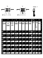
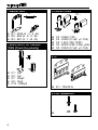
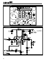
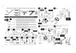
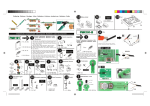
Total solder points: 44
Skill level :
Beginner 1o 2þ 3o 4o 5o Advanced
K2637
SUPER MINI 2.5W AUDIO POWER AMPLIFIER
Manual
Specifications :
þ Max. output power : 2.5W (4Ω /12V)
þ Frequency response : 60Hz - 15KHz
þ Input sensitivity : 20-150mV selectable
þ Thermal and short circuit protection
þ Power supply : 4.5 - 15VDC /400mA
þ Quiescent current : 12mA
þ Dimensions : 42x32mm (1.65”x1.25”)
modifications reserved
Applications :
þ Small but powerful multi-purpose amplifier
þ For use with portable audio equipment
þ Power amplifier for audio projects
þ In-car use
þ Your own unique application
MANUAL
H2637-ED1
5%
1%
4K7= ( 4 - 7 - 2 - B )
I
P
C CODICE CODIGO
O COLORE
DE
D
CORES
E
0
1
2
3
4
5
6
7
8
9
A
B
Nero
Marrone
Rosso
Aranciato
Giallo
Verde
Blu
Viola
Grigio
Bianco
Argento
Oro
Preto
Castanho
Encarnado
Laranja
Amarelo
Verde
Azul
Violeta
Cinzento
Branco
Prateado
Dourado
COLOR= 2… 5
4K7= ( 4 - 7 - 0 - 1 - 1 )
E
CODIGO
DE COLORES
Negro
Marrón
Rojo
Naranjado
Amarillo
Verde
Azul
Morado
Gris
Blanco
Plata
Oro
SF
VÄRI
KOODI
Musta
Ruskea
Punainen
Oranssi
Keltainen
Vihreä
Sininen
Purppura
Harmaa
Valkoinen
Hopea
Kulta
S
DK
N
FÄRG FARVE FARGE
SCHEMA KODE KODE
Svart
Brun
Röd
Orange
Gul
Grön
Blå
Lila
Grå
Vit
Silver
Guld
Sort
Brun
Rød
Orange
Gul
Grøn
Blå
Violet
Grå
Hvid
Sølv
Guld
Sort
Brun
Rød
Orange
Gul
Grønn
Blå
Violet
Grå
Hvidt
Sølv
Guldl
D
FARB
KODE
Schwarz
Braun
Rot
Orange
Gelb
Grün
Blau
Violet
Grau
Weiss
Silber
Gold
GB
F
COLOUR CODIFI-
CODE
CATION
DES
COULEURS
Black
Brown
Red
Orange
Yellow
Green
Blue
Purple
Grey
White
Silver
Gold
Noir
Brun
Rouge
Orange
Jaune
Vert
Blue
Violet
Gris
Blanc
Argent
Or
NL
KLEUR
KODE
C
O
D
E
Zwart
Bruin
Rood
Oranje
Geel
Groen
Blauw
Paars
Grijs
Wit
Zilver
Goud
0
1
2
3
4
5
6
7
8
9
A
B
__________________________________________________________________________________________________________________________________________________________
1. Assembly (Skipping this can lead to troubles ! )
Ok, so we have your attention. These hints will help you to make this project successful.
Read them carefully.
1.1 Make sure you have the right tools:
• A good quality soldering iron (25-40W) with a
small tip.
• Wipe it often on a wet sponge or cloth, to keep
it clean; then apply solder to the tip, to give it a
wet look. This is called ‘thinning’ and will protect the tip, and enables you to make good connections. When solder rolls off the tip, it needs cleaning.
• Thin raisin-core solder. Do not use any flux or grease.
• A diagonal cutter to trim excess wires. To avoid injury
when cutting excess leads, hold the lead so they cannot fly towards the eyes.
• Needle nose pliers, for bending leads, or to hold components in place.
• Small blade and phillips screwdrivers. A basic range is fine.
For some projects, a basic multi-meter is required, or might be
handy
0.0
00
1.2 Assembly Hints :
þ
þ
þ
þ
þ
þ
þ
þ
Make sure the skill level matches your experience, to avoid disappointments.
Follow the instructions carefully. Read and understand the entire step before you perform each operation.
Perform the assembly in the correct order as stated in this manual
Position all parts on the PCB (Printed Circuit Board) as shown on the drawings.
Values on the circuit diagram are subject to changes.
Values in this assembly guide are correct*
Use the check-boxes to mark your progress.
Please read the included information on safety and customer service
* Typographical inaccuracies excluded. Always look for possible last minute manual updates, indicated as ‘NOTE’
on a separate leaflet.
1.3 Soldering Hints :
Mount the component against the
PCB surface and carefully solder the
leads
Make sure the solder joints are
cone-shaped and shiny
Trim excess leads as close as possible to the solder joint
3
_______________________________________________________________________________________________________________________________________________________
1. RESISTORS
3. CAPACITORS
R...
q R1 : 330K (3 - 3 - 4 - B)
q R2 : 5K6 (5 - 6 - 2 - B)
q R3 : 4E7 (4 - 7 - B - B)
2. ELECTROLYTIC CAPACITORS (Check the polarity)
C...
q
q
q
q
q
C1 : 1µF
C2 : 1µF
C7 : 100µF
C9 : 10µF
C10 : 1000µF
C...
q
q
q
q
q
C3 : 100pF (101)
C4 : 100nF (0.1µF; µ1; 104)
C5 : 1.8nF (182; 1800)
C6 : 220nF (224; 0.22µ; µ22)
C8 : 100nF (0.1µF; µ1; 104)
4. IC
q IC1 : TDA1015
6. PCB TERMINALS
q
4
__________________________________________________________________________________________________________________________________________________________
7. CONNECTION EXAMPLE
LOW LEVEL INPUT
4/8 OHM SPEAKER
+
-
-
+
4.5 .. 15VDC
+
JUMPER
Dynamic microphone
8. CONNECTION EXAMPLE HIGH LEVEL INPUT
4/8 OHM SPEAKER
CD PLAYER
TAPE RECORDER
VIDEO RECORDER
COMPUTER
…
+
-
-
4.5 .. 15VDC
+
NO JUMPER
VOLUME
47K ohm log
5
_______________________________________________________________________________________________________________________________________________________
9. PCB LAYOUT
10. DIAGRAM
6