1
O110
Active
Studio Monitor
Installation and Operation
Safety Instructions
It is absolutely essential that you read these safety instructions carefully before connecting and using this K+H
product. Your safety depends on it. Furthermore, failure to follow these instructions voids the warranty. To
ensure safe operation for years to come, keep these instructions in a safe place for future reference. K+H has
manufactured this product in accordance with IEC 92 (SEC) 39 standards, then tested and delivered it in safe operating
condition. To maintain it in this condition, you must:
•
•
•
•
observe all safety instructions,
use the product only as described herein,
have any maintenance, repairs, or modifications performed only by K+H or other authorized personnel, and
ensure that the room in which you use this product is wired in accordance with the local electrical code.
Warning!
•
When the interior of the cabinet is exposed, touching some parts can lead to an electric shock.
•
If you need to gain access to the interior electronics of the unit, always disconnect the unit from any and all power
sources first.
•
Any repairs, maintenance, or other service of the unit when its interior compartment is exposed may only be
performed safely (in accordance with VBG 4) by authorized technicians familiar with all the risks involved. Even in
an unplugged state, a fully charged capacitor in the unit can zap the unsuspecting.
•
Loudspeaker output jacks labeled with the IEC 417/5036 emblem (Fig. A, right) may be carrying
dangerously high voltages. If your unit has this emblem, ensure that any connections to be made
between these jacks and the speakers themselves are made before powering up the unit, and
are done so only with manufacturer-approved interconnecting cables.
•
If you need to replace any fuses, ensure that the replacements are of exactly the same type,
value and voltage as the originals, as spelled out in the technical specifications at the rear of this
manual.
•
Do not use "repaired" fuses.
Fig. A
•
If you do not have any fuses on hand of the specified size, type, and value, do not hot-wire the
contacts in the holder by short-circuiting them.
•
Certain areas of the cabinet, cover, and rear panel can achieve extreme temperatures and are
therefore marked with a "HOT" label (Fig. B). Refrain from touching any heat sink or ventilation
grille.
•
High volume levels are known to cause permanent - i.e. irreversible - hearing damage, especially
when listened to without sufficient breaks. The higher the levels, the more frequent and extended
must be the breaks. Avoid standing too close to loudspeakers that are being driven at high
levels. If you must be exposed to high sound pressure levels over an extended period of time,
use hearing protection.
Fig. B
Mains Connection:
•
This unit is designed for continuous operation.
•
Ensure that the operating voltage of the unit matches that of the local mains current (AC line voltage).
•
Always check before connecting the power cable to the mains socket that the power switch on the unit itself is set
to off ("O").
•
Use the power cable or power supply that came with the unit to connect to the mains socket (wall outlet).
•
Power supply: a damaged power cable may not be repaired. Use a new cable.
•
Avoid plugging the mains cable into a power strip that already has several other power-consuming devices connected
to it.
•
Avoid using extension cables. The unit must be connected to a mains socket close to it, and that socket should be
freely accessible.
Installation:
•
This product may only be placed on a stable, clean, horizontal surface.
•
Do not expose this product to vibration.
•
Do not operate this product anywhere near water or other liquids. Do not use it near a sink, swimming pool,
bathtub, or in any damp room or area. Electrical shocks carried through water can kill. Do not place any beverages
whatsoever on or near this product, as liquids can kill electronic components.
•
Ensure sufficient ventilation around the product to allow for adequate heat dissipation, especially near the rear
panel and the sides of the cabinet (minimum of 8 inches from the nearest wall). The unit may only be installed in a
rack if measures are taken to ensure sufficient ventilation and if the mounting instructions of the manufacturer are
followed. Do not block or cover any heat sink, fan, or vent.
•
Do not place the product where it will be in the path of direct sunlight, and keep it a safe distance away from
radiators and other heaters of any kind.
•
If you bring this product from a cold environment into a warm one (such as from a vehicle into a studio), it is quite
possible that condensation will form inside the cabinet. Please allow the unit sufficient time for acclimatisation to
room temperature (minimum thirty minutes) before connecting and powering up.
•
To avoid accidents, do not use any accessory equipment with this product which is not approved by the manufacturer,
particularly mounting accessories. Do not place this unit on any unstable platform, cart, stand or table. Should the
unit fall, it can cause bodily injury to persons, or can be damaged itself.
•
To protect this product from lightning damage during a thunderstorm or from power surges during an extended
absence, disconnect the power cable from the wall outlet.
Page 2
Active Studio Monitor O 110
Active Studio Monitor
KLEIN + HUMMEL O 110
Installation - Operation
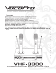
Figure 1: Front view of the O 110
Figure 2: Rear panel of the O 110
Table of Contents:
Safety Instructions......................................................2
1.6 Mains Power Fuse.........................................5
Table of Contents....................................................3
1.7 Display Functions.........................................5
1.7.1 Overload Protection....................................5
1. Installation and Operation....................................4
1.8 Care of the Cabinet........................................6
1.1 Operating Conditions......................................4
2. Diagrams............................................................6
1.2 Installation....................................................4
3. Warranty Information...........................................8
1.3 Connection to Mains Current...........................4
4. EC Declaration of Conformity...............................8
1.4 POWER Switch............................................4
5. Technical Specifications.....................................9
1.5 Level / Room Compensation / Ground Lift.......4
1.5.1 Input Level Adjustment...............................4
1.5.2 Equalization..............................................4
1.5.3 Ground Lift.................................................5
Active Studio Monitor O 110
Page 3
1. Installation and Operation
It is absolutely essential that you read and
observe the Safety Instructions on page 2
before connecting or using this device.
1.1 Operating Conditions
The K+H model O 110 active studio monitor is
intended for use over a range of ambient
temperatures from +10° C to +40° C (+50° F to
+104° F). During transport or storage,
temperatures from -25° C to +70° C (-13° F to
158° F) are permissible.
1.2 Installation
The loudspeaker chassis used in the O 110 are
magnetically shielded, allowing these loudspeakers to be mounted side by side with
a video or computer monitor without adversely
affecting the screen. One of the finer features
of the O 110 active studio monitor is its unusually
uniform off - axis directivity, which results in a very
wide ”sweet spot”. Preferred placement of the
cabinet is in the upright position, for the dispersion
in the verical plane was intentionally kept narrower
than in the horizontal.
In certain cases, for example if there are hard,
reflective surfaces both to the left and right of
the loudspeakers, it would make sense to
operate the loudspeakers on their side. The
reduced horizontal directivity in this position would
then be helpful in minimizing any phase cancellation caused by comb - filter effects.
1.3 Connection to Mains Current
The amplifier electronics within the O 110 are
set up for an AC line voltage of 230 volts, 50 or 60
cycles per second. For export, special versions
with other AC voltages are also available. If it
becomes necessary to use a different mainscable plug, pay attention to proper grounding
when wiring a replacement plug.
1.4 POWER Switch
When you switch power on, there is a 7 second
delay before the amplified signal is sent
to the loudspeakers. This delay avoids the loud
popping sounds that otherwise are generated
by prior devices in the signal chain as they are
switched on. You will find this arrangement
particularly useful if your studio uses a master
switch to power up all the equipment at once.
When power on the O 110 is turned off, on the
other hand, or if there is a general power failure in
the area, the signal flow to the speaker is
immediately stopped, preventing any loud pops.
1.5 Level / Room Compensation / Ground Lift
1.5.1 Input Level Adjustment
The sensitivity of the electronically balanced
input is rated at +6 dBu (1.55 volts). The
three - pole female XLR jack is wired in the
standard manner (pin 1 = ground, pin 2 = +,
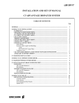
pin 3 = negative). If you are connecting unbalanced
sources, you will need to solder a bridge between
pins 1 and 3:
When considering placement, please take into
consideration the possibilities offered by both of
the room compensation switches described in
section 1.5.2.
On the back of the unit you will find two M8-style
threaded bushings for use with various mounting
options. These holes are labeled ”Speaker mount
option.” The bushings will accommodate either the
LH 32 wall bracket adapter or the LH 31 mounting
bracket for use with additional mounting
accessories.
!
The plastic screws that occupy these
threaded holes from the factory may not
be used for the actual mounting of a
loudspeaker under any circumstances.
Please ensure that these threaded holes are
always plugged so that the volume of air sealed
within the cabinet may only pass through the
precisely calculated bass - reflex openings.
Page 4
unbalanced
balanced
as seen from solder terminals of male XLR
Figure 3: Pin layout of input connector
Directly beside this XLR jack you will find the
ATTENUATOR pot, which allows for smooth, gradual damping of the input signal by anywhere from
0 to 24 dB. As an option, you can order the O 110
with transformer - balanced inputs.
1.5.2 Equalization
1.5.2.1 BASS Switch
The four-position rotary switch labeled BASS (see
Figure 2, Equalization section) serves to alter the
frequency response of the loudspeaker to
compensate for the overemphasis of low
frequencies that may result from the specific location
at which the speaker is placed within the room:
Active Studio Monitor O 110
Position 0 = free standing
Position 1 = placement a short distance
before a wall
Position 2 = placement flat against a wall
Position 3 = placement in a corner of the room
circuit board below the XLR jack. The arrow is
pointing to a jumper, which by default bridges the
two pins. If you remove the jumper the signal
ground is lifted from the chassis ground. Of course
the chassis ground always remains connected to
the protective earth conductor.
1.5.2.2 MID Switch
If the loudspeakers are placed on the meter bridge,
a certain overemphasis in the midrange will
typically result. Next to the four-position switch for
room compensation which we just described,
there is another four-way rotary switch labeled
MID. The four switch settings are intended for the
following kinds of placement:
Position 0 =
Position A =
Position B =
Position C =
free standing
placement on a table top
free standing on the meter bridge
on the meter bridge between
other equipment directly on either
side, or built into a wall.
Note: Since it is not possible to list all possible
combinations of speaker placement and room
acoustics, we strongly recommend checking the
switch settings acoustically or by measurement.
The frequency response curves of both equalizers
are shown in Figure 12 in section 2, diagrams.
1.5.3 GROUND LIFT
Since the input is balanced, a ground loop hum
will rarely occur. In special cases or if the source
signal is unbalanced, it can become necessary
to separate the signal ground from chassis ground.
To do so, first unplug the mains cable from the
mains socket, of course, then unscrew and remove
the back panel, which has the amplifier electronics
mounted directly to it. Figure 4 shows the amplifier
!
Warning!
The protective earth conductor must
never be interrupted even for test
purposes! This may be dangerous to life!
1.6 Mains Power Fuse
Should you ever need to replace the power fuse,
please ensure (first of all that the unit is unplugged
from the mains!) and that only the following type
and value of fuse is used:
For 230-240 volts AC: 1 A Slo-Blo (5 x 20 mm)
For 117 volts AC:
2 A Slo-Blo (5 x 20 mm)
For 100 volts AC:
2.5 A Slo-Blo (5 x 20 mm)
1.7 Display Functions
The illuminated K+H logo serves as a status
display for the loudspeaker when the power
switch is on and the fuse is intact:
Continuous red: Normal operation, internal
supply of power is in order
Blinking red:
Overload protection circuitry
engaged
If the light is blinking, this indicates that the
overload protection circuitry has been triggered.
Among the things that can trigger it are the
”scrubbing” of analog tape in cue - mode,
extremely bass - heavy signals or the sine - wave
signals that are used in performing measurements.
The protection circuitry limits the output power of
the amplifier to a level that is safe for the speaker.
If the output level should drop as in one of these
cases, check for the cause and, if necessary,
reduce the monitoring level.
1.7.1 Overload Protection
As we just described above, the protection circuit
limits the signal to safe levels. This occurs so
gradually, that under certain circumstances you
may not even notice that the protection circuitry
has been triggered and the signal is being limited
in dynamic range. But by moving an internal
jumper you can change how this circuit responds,
so that when it is activated, it will cause a clearly
audible drop in level (hard position). To access
this jumper, unplug the mains cable from the
mains socket, unscrew and remove the rear panel,
on the other side of which you will find the amplifier
Figure 4: Ground Lift Connection
Active Studio Monitor O 110
Page 5
electronics. In Figure 5, the arrow points to the
spot on the input circuit board where the jumper
is located, next to the XLR input jack.
1.8 Care of the Cabinet
The cabinet housing of the K+H O 110 active studio
monitor has a painted finish. Handle the cabinet
with care to avoid damaging the finish. To clean
the cabinet, use a soft cloth with a mild cleaning
agent only. To clean the cabinet, use a soft cloth
with a mild cleaning agent only. Under no
circumstances should you use chemical agents
or any cleaners with abrasive action.
Figure 5: Jumper for Overload Protection Circuit
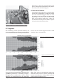
2. Diagrams
The outstanding acoustic impression made by the
O 110 is confirmed by measurements using today’s
most critical test methods. The test plots shown here
and on the next several pages are but a small
sampling of these measurements.
Figure 6: Horizontal Directivity
Figure 7: Vertical Directivity
Using the new material LRIM (Low Resonance Integral Molding) allowed us to seamlessly integrate a
waveguide into the baffle that is ideal for optimal
dispersion. So an elliptical horn for the tweeter was
Page 6
added. Thus came to be the dispersion pattern we
mentioned earlier which is narrower vertically and
broader horizontally, as is clearly evident in the test
plots presented in Figures 6 and 7.
Active Studio Monitor O 110
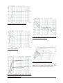
Figure 8: Frequency Response (free field)
Figure 9: THD, 2 nd and 3 rd order distortion
@ 95 dB/SPL and 1 m distance
Figure 10: Group Delay
Figure 11: Cumulative Spectral Decay Plot
The loudspeaker’s cumulative spectral decay plot
indicates a very clean decay without any major
resonances or standing waves being evident.
Figure 12: Equalization BASS (upper set of curves)
and MID (lower set of curves)
Active Studio Monitor O 110
Page 7
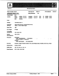
3. Warranty Information
All K+H products undergo an extensive procedure of
quality control testing before leaving the factory. Before
semiconductors are mounted on the circuit board,
they are subject to rigorous tests. Every single unit is
guaranteed to match its technical specifications within
strict predetermined tolerances.
Please store the original carton in a safe, dry place. If
you should ever need warranty service, put the unit
in its original packing material and carton together
with a detailed description of the problem, and ship it
(freight prepaid) to our distributor.
K+H warrants, that the product is free from any defects
in both material and manufacturing and that it meets
the specifications. A warranty case can only be
acknowledged under condition that the complaint is
filed to our distributor or to us in writing within 8 days
after delivery or detection of the fault. Not covered
under this warranty are damages due to inexpert
packing and shipment, wear and tear, improper
handling, installation, operation and maintenance.
The limitation period for warranty claims is described
in the terms and conditions of K+H GmbH. Its our
choice to repair, to supply a new product or to
withdraw from the contract.
In the event warranty service is required, presentation
of a warranty card will not be necessary. Proof of
purchase date can be made by filing copies of
appropriate documents (invoice, delivery note).
4. EC Declaration of Conformity
This equipment is in compliance with the essential
requirements and other relevant provisions of
Directives 89/336/EC and 73/23/EC. The declaration
is available on the internet site at
www.klein-hummel.com. Before putting the device into
operation, please observe any respective countryspecific regulations.
Page 8
Active Studio Monitor O 110
5. Technical Specifications
O 110
Maximum SPL
in half space, 3% THD at 1 m distance
averaged between
107.7 dB/SPL
100 Hz and 6 kHz
Free field frequency response
58 Hz - 20 kHz ± 2 dB
Self generated noise level at 10 cm
< 20 dB(A)
Total Harmonic Distortion
150 Hz and above @ 1 m
< 0.5 % @ 90 dB/SPL
Directivity
Horizontal
Vertical
Electronics
Power amplifiers
Bass amplifier
Treble amplifier
Crossover section
Crossover frequency
Crossover slopes
Protection circuit
Input
Impedance
Sensitivity
Volume control
Common mode rejection ratio
± 40° (-6 dB)
± 30° (-6 dB)
50 W at 6 Ohm (THD < 0.1 %)
50 W at 6 Ohm (THD < 0.1 %)
2.5 kHz
24 dB / octave
against overload of both drivers
14 kOhm (electronically balanced)
14 kOhm (transformer balanced floating)
+ 6 dBu
continuously variable from 0...-24 dB
> 50 dB @ 15 kHz
Equalization
4 position switch positioning on mixing console 0; -1.5; -3; -5 dB
4 position switch positioning on rear/side walls 0; -2.5; -5; -7.5 dB
Drivers
Connectors
Bass
Treble
magneticallay shielded
5.5” Ø, Composite - Sandwich - Diaphragm
1” Ø, Titanium Fabric Dome Tweeter
Mains
Signal input
3 - terminal Euro connector
XLR connector 3-pin female
Power consumtion
Idle
Full power
10 VA
70 VA
Mains
230 V or 120V or 100V fixed, verify label on device
Dimensions (W x H x D)
170 x 267 x 190 mm (6.7” x 10.5” x 7.5”)
Volume
8.6 liters (0.30 cubic feet)
Weight
5.0 kg (11 pounds)
Cabinet finish
enamel anthracite RAL 7021 or silver RAL 9006
Accessories
LH 31 mounting bracket
LH 28 tripod bushing (LH 31 mounting bracket required)
LH 29 TV - spigot (LH 31 mounting bracket required)
LH 27 ball clamp mount (LH 31 mounting bracket required)
LH 7 or LH 8 adaptor (LH 31 mounting bracket required)
LH 32 wall bracket
C 15 eyebolt
KG 30 ball clamp mount
Active Studio Monitor O 110
Page 9
K+H Vertriebs- und Entwicklungsgesellschaft mbH
30900 Wedemark, Germany
Phone +49 (5130) 58 48 0
Fax +49 (5130) 58 48 11
www.klein-hummel.com
Printed 12/07
518114