1
3
Simulator CDSM-S1
Safety conditions
Warning
Festo AG & Co. KG
Postfach
D-73726 Esslingen
++49/711/347-0
www.festo.com
Operating instructions
734 966
0804NH
Note
Operating elements and connections
1 2 3
4
5
6
7
These operating instructions are directed exclusively at personnel trained in
commissioning and servicing, who have detailed knowledge of the functions and
characteristics of the device connected to the simulator and of the relevant
machine/system.
Improper handling can result in malfunctions.
• Make sure that all the instructions in this chapter are observed. The product
will then function correctly and reliably.
Original: de
1
Modification to the signal states and parameters with the simulator can trigger
dangerous movements of the connected actuators.
• Make sure that nobody is in the positioning range of the connected actuators
and be very careful with the parametrising and the manipulation of signal
states.
8
•
•
•
•
•
The product is not a safety component and must only be used as designated.
Unauthorised product modification is not permitted.
Make sure that safety measures cannot be ignored.
Ensure that all applicable national and local safety laws are adhered to.
Compare the maximum values specified in these operating instructions with
your actual application (e.g. forces, torques, masses, speeds, temperatures).
The product can only be used in accordance with the relevant safety guidelines if
the maximum loading limits are observed.
• Take into consideration the ambient conditions at the location of use.
• Please note the instructions and explanations in the relevant description for the
controllers.
4
Installation
Note
An incorrect connection allocation may destroy the simulator. Use only the
supplied original cable from Festo. The power supply for the simulator is
provided by the connected controller.
• Connect the connectors as follows:
– Connector (A) to controller using supplied cable. The pin allocation is
summarised in the description for the controller.
– Connector (B) for external limit switches.
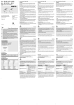
Fig. 1
1
2
3
4
5
aC aB
Selector switch for limit switches
(external/internal)
Selector switches for presetting
the controller type CMMS or CMMP
(both switches must be set to the
same type)
Rotary switch for position set
selection
Sockets for analogue outputs
(e g. for oscilloscope)
Potentiometers for setting the
voltage of the analogue inputs
aA aJ 9
6
7
8
9
aJ
aA
aB
aC
Selector switches for use as
analogue or digital inputs
Toggle switches for digital inputs
Selector switch for use as output
or input
Toggle switch: Start
Toggle switch for output stage
enable
Toggle switch for controller enable
Toggle switch for simulation of
limit switches (internal)
Toggle switch for digital input Din3
(only for CMMS)
Fig. 2
2
Function and application
The CDSM-S1 simulator is intended for use in simulating input and output signals
for controllers of type CMMS, CMMP and SEC-AC from Festo during commissioning.
Continuous use during operation is not permitted.
In order to use the simulators, you must generally have detailed knowledge of the
functions and features of the connected controller. Further information on use in
conjunction with the relevant controller can be found in the manual for the
product. You must observe the:
– safety precautions and the
– designated use of the product.
(A)
(B)
Fig. 3
PIN
Allocation
1
24 V
(out)
Connector (B)
2
Limit switch Limit 1 (external)
(in)
3
0V
(out)
4
24 V
(out)
5
Limit switch Limit 0 (external)
(in)
6
0V
(out)
Fig. 4