1
NX-720H NX-720HG
NX-820H NX-820HG
NX-920 NX-920G
VHF DIGITAL TRANSCEIVER
UHF DIGITAL TRANSCEIVER
800MHz DIGITAL TRANSCEIVER
INSTRUCTION MANUAL
ÉMETTEUR-RÉCEPTEUR NUMÉRIQUE VHF
ÉMETTEUR-RÉCEPTEUR NUMÉRIQUE UHF
ÉMETTEUR-RÉCEPTEUR NUMÉRIQUE 800MHz
MODE D’EMPLOI
TRANSCEPTOR DIGITAL VHF
TRANSCEPTOR DIGITAL UHF
TRANSCEPTOR DIGITAL 800MHz
MANUAL DE INSTRUCCIONES
© B62-2560-00 (K)
09 08 07 06 05 04 03 02 01 00
NX-720H
NX-820H
NX-920
NX-720HG
NX-820HG
NX-920G
INSTRUCTION MANUAL
ENGLISH
VHF DIGITAL TRANSCEIVER
UHF DIGITAL TRANSCEIVER
800MHz DIGITAL TRANSCEIVER
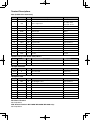
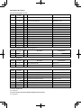
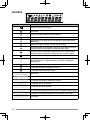
Terminal Descriptions
ACC (D-SUB 15 Pin Connector)
Pin No.
Name
I/O
1
SB
O
DC Power (Switched B) Output
Description
Specification
2
IGN
I
Igintion Signal Input
3
SP2/PA
O
Loudspeaker Output/ Public Address Output
4
DETO
O
RX Detected Audio Output
280 mVp-p (typ.)
5
DATAI
I
TX Data Input
100 k
6
FNC1/ TXD
I/O
Programmable/ PC Serial Data from Radio
High Impedance
7
FNC2/ RXD
I/O
Programmable/ PC Serial Data to Radio
High Impedance
8
FNC3
I/O
Programmable
High Impedance
9
FNC4
I/O
Programmable
High Impedance
10
FNC5
I/O
Programmable
High Impedance
11
FNC6
I/O
Programmable
High Impedance
12
50MC
O
DC Power Output
5 V, Max 100 mA
13
HR1
I
Horn Alert Signal Input
Max 2 A
13.6 V ±15% Max. 2 A
Min. Input: 10.8 V
Max. Input: 16.0 V
4
14
HR2
O
Horn Alert Signal Output
Max 2 A
15
GND
—
Ground
Ground
Speaker Jack (3.5 mm Phone Jack) 4 W/ 4
Pin No.
Name
I/O
1
SPO
O
External Speaker Output
Description
4
Specification
3
GND
—
Ground
Ground
DC Input Connector
Pin No.
Name
I/O
Red
B
I
DC Power Input
Description
13.6 V ±15%
Specification
Black
GND
I
Ground
Ground
Microphone Jack
Pin No.
Name
I/O
Description
1
MBL
O
MIC Backlight Control
High Impedance
2
SB
O
DC Power (Switched B) Output
13.6 V ±15%
3
GND
—
Ground
Ground
4
PTT/ TXD
I/O
PTT/ PC Serial Data from Radio
High Impedance
5
ME
—
Mic Ground
Ground
6
MIC
I
Mic Signal Input
600
7
HOOK/ RXD
I
Hook/ PC Serial Data to Radio
High Impedance
8
DM
I/O
Mic Data Detection
High Impedance
RF Antenna Terminal
50 impedance
GPS Antenna Terminal <NX-720HG/ NX-820HG/ NX-920G only>
50 impedance
Specification
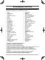
THANK YOU
We are grateful you have chosen KENWOOD for your personal mobile applications.
This instruction manual covers only the basic operations of your mobile radio. Ask your dealer for
information on any customized features they may have added to your radio.
NOTICES TO THE USER
◆ Government law prohibits the operation of unlicensed transmitters within the territories under
government control.
◆ Illegal operation is punishable by fine and/or imprisonment.
◆ Refer service to qualified technicians only.
SAFETY: It is important that the operator is aware of, and understands, hazards
common to the operation of any transceiver.
◆ EXPLOSIVE ATMOSPHERES (GASES, DUST, FUMES, etc.)
Turn OFF your transceiver while taking on fuel or while parked in gasoline service stations. Do
not carry spare fuel containers in the trunk of your vehicle if your transceiver is mounted in the
trunk area.
◆ INJURY FROM RADIO FREQUENCY TRANSMISSIONS
Do not operate your transceiver when somebody is either standing near to or touching the
antenna, to avoid the possibility of radio frequency burns or related physical injury.
◆ DYNAMITE BLASTING CAPS
Operating the transceiver within 500 feet (150 m) of dynamite blasting caps may cause them
to explode. Turn OFF your transceiver when in an area where blasting is in progress, or where
“TURN OFF TWO-WAY RADIO” signs have been posted. If you are transporting blasting caps
in your vehicle, make sure they are carried in a closed metal box with a padded interior. Do not
transmit while the caps are being placed into or removed from the container.
One or more of the following statements may be applicable:
FCC WARNING
This equipment generates or uses radio frequency energy. Changes or modifications to this
equipment may cause harmful interference unless the modifications are expressly approved in the
instruction manual. The user could lose the authority to operate this equipment if an unauthorized
change or modification is made.
INFORMATION TO THE DIGITAL DEVICE USER REQUIRED BY THE FCC
This equipment has been tested and found to comply with the limits for a Class B digital device,
pursuant to Part 15 of the FCC Rules. These limits are designed to provide reasonable protection
against harmful interference in a residential installation.
This equipment generates, uses and can generate radio frequency energy and, if not installed and
used in accordance with the instructions, may cause harmful interference to radio communications.
However, there is no guarantee that the interference will not occur in a particular installation. If this
equipment does cause harmful interference to radio or television reception, which can be determined
by turning the equipment off and on, the user is encouraged to try to correct the interference by one
or more of the following measures:
• Reorient or relocate the receiving antenna.
• Increase the separation between the equipment and receiver.
• Connect the equipment to an outlet on a circuit different from that to which the receiver is
connected.
• Consult the dealer for technical assistance.
i
PRECAUTIONS
Observe the following precautions to prevent fire, personal injury, and transceiver
damage.
• Do not attempt to configure the transceiver while driving; it is too dangerous.
• Do not disassemble or modify the transceiver for any reason.
• Do not expose the transceiver to long periods of direct sunlight, nor place it near heating
appliances.
• If an abnormal odor or smoke is detected coming from the transceiver, switch the
transceiver power off immediately, and contact your KENWOOD dealer.
• Use of the transceiver while you are driving may be against traffic laws. Please check
and observe the vehicle regulations in your area.
• Do not use options not specified by KENWOOD.
◆ The transceiver operates in 12 V negative ground systems only! Check the battery polarity and
voltage of the vehicle before installing the transceiver.
◆ Use only the supplied DC power cable or a KENWOOD optional DC power cable.
◆ Do not cut and/or remove the fuse holder on the DC power cable.
For passenger safety, install the transceiver securely using the supplied mounting bracket and
screw set so the transceiver will not break loose in the event of a collision.
CONTENTS
GETTING STARTED ...................................................................................... 1
GETTING ACQUAINTED ............................................................................... 3
PROGRAMMABLE FUNCTIONS .................................................................. 5
BASIC OPERATIONS .................................................................................... 6
SCAN ............................................................................................................. 8
FleetSync: ALPHANUMERIC 2-WAY PAGING FUNCTION ....................... 10
TRUNKING CALLS (ANALOG)................................................................... 12
DTMF CALLS............................................................................................... 13
ADVANCED OPERATIONS ......................................................................... 15
BACKGROUND OPERATIONS ................................................................... 18
ii
GETTING STARTED
Note: The following instructions are for use by your KENWOOD dealer, an authorized KENWOOD
service facility, or the factory.
SUPPLIED ACCESSORIES
Carefully unpack the transceiver. We recommend that you identify the items listed below
before discarding the packing material. If any items are missing or have been damaged
during shipment, file a claim with the carrier immediately.
DC power cable (with fuses) . . . . . . . . . . . . . . . . . . . . . . . . . . . . . . . . . . . . . . . . . . . . . . . . . . . . . . 1
• 15 A fuse . . . . . . . . . . . . . . . . . . . . . . . . . . . . . . . . . . . . . . . . . . . . . . . . . . . . . . . . . . . . . . . . . 2
Mounting Bracket . . . . . . . . . . . . . . . . . . . . . . . . . . . . . . . . . . . . . . . . . . . . . . . . . . . . . . . . . . . . . . 1
Screw set
• 5 x 16 mm self-tapping screw. . . . . . . . . . . . . . . . . . . . . . . . . . . . . . . . . . . . . . . . . . . . . . . . . . 4
• M4 x 6 mm hex-headed screw with washer . . . . . . . . . . . . . . . . . . . . . . . . . . . . . . . . . . . . . . . 4
• Spring washer . . . . . . . . . . . . . . . . . . . . . . . . . . . . . . . . . . . . . . . . . . . . . . . . . . . . . . . . . . . . . 4
• Flat washer. . . . . . . . . . . . . . . . . . . . . . . . . . . . . . . . . . . . . . . . . . . . . . . . . . . . . . . . . . . . . . . . 4
Microphone (with cable)
• KMC-35 . . . . . . . . . . . . . . . . . . . . . . . . . . . . . . . . . . . . . . . . . . . . . . . . . . . . . . . . . . . . . . . . . . 1
Microphone hanger (with 4 x 16 mm self-tapping screws) . . . . . . . . . . . . . . . . . . . . . . . . . . . . . . . 1
Instruction manual . . . . . . . . . . . . . . . . . . . . . . . . . . . . . . . . . . . . . . . . . . . . . . . . . . . . . . . . . . . . . 1
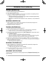
PREPARATION
Various electronic equipment in your vehicle may malfunction if they are not properly protected from
the radio frequency energy which is present while transmitting. Typical examples include electronic
fuel injection, anti-skid braking, and cruise control. If your vehicle contains such equipment, consult
the dealer for the make of vehicle and enlist his/her aid in determining if they will perform normally
while transmitting.
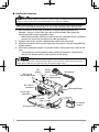
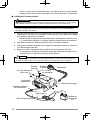
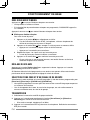
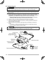
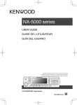
■ Power Cable Connection
The transceiver operates in 12 V negative ground systems only! Check the battery polarity and
voltage of the vehicle before installing the transceiver.
1
2
3
4
Check for an existing hole, conveniently located in the firewall, where the power
cable can be passed through.
• If no hole exists, use a circle cutter to drill a hole, then install a rubber grommet.
Run the power cable through the firewall and into the engine compartment.
Connect the red lead to the positive (+) battery terminal and the black lead to the
negative (–) battery terminal.
• Place the fuse as close to the battery as possible.
Coil the surplus cable and secure it with a retaining band.
• Be sure to leave enough slack in the cables so the transceiver can be removed
for servicing while keeping the power applied.
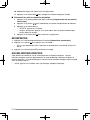
1
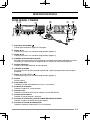
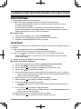
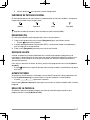
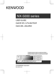
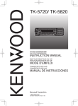
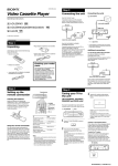
■ Installing the Transceiver
For passenger safety, install the transceiver securely using the supplied mounting bracket and
screw set, so the transceiver will not break loose in the event of a collision.
Note: Before installing the transceiver, check how far the mounting screws will extend below
the surface. When drilling mounting holes, be careful not to damage vehicle wiring or parts.
1
2
3
4
Mark the position of the holes in the dash, using the mounting bracket as a
template. Using a 4.2 mm (5/32 inch) drill bit, drill the holes, then attach the
mounting bracket using the supplied screws.
• Mount the transceiver within easy reach of the user and where there is sufficient
space at the rear of the transceiver for cable connections.
Connect the antenna and the supplied power cable to the transceiver.
Slide the transceiver into the mounting bracket and secure it using the supplied hexheaded screws.
Mount the microphone hanger in a location where it will be within easy reach of the
user.
• The microphone and microphone cable should be mounted in a place where
they will not interfere with the safe operation of the vehicle.
When replacing the fuse in the DC power cable, be sure to replace it with a fuse of the same
value. Never replace a fuse with one that is rated with a higher value.
Flat
washer
M4 x 6 mm
Hex-headed screw
Spring
washer
Microphone
5 x 16 mm
Self-tapping screw
RF antenna
connector
Mounting bracket
Power input
connector
Black (–) cable
Red (+) cable
12 V vehicle
battery
DC power cable
Fuse
2
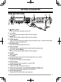
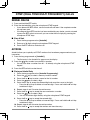
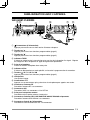
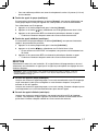
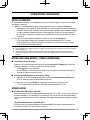
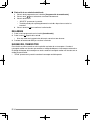
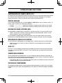
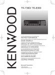
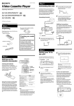
GETTING ACQUAINTED
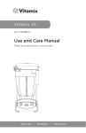
FRONT AND REAR VIEWS
ab
d ef
j
c
g
h
i
a
(Power) switch
Press to switch the transceiver ON or OFF.
b
/ keys
Press to activate their programmable functions {page 5}.
c
/ keys
Press to activate their programmable functions {page 5}.
k
l
m
n
d TX/RX Indicator
Lights red while transmitting and green while receiving a signal. Flashes orange when
receiving an optional signaling call.
e Microphone jack
Insert the microphone plug into this jack.
f Status Indicator
Lights blue during a specified mode, based on dealer programming.
g
/ S / A / <B / C> / ■ keys
Press to activate their programmable functions {page 5}.
h Speaker
Internal speaker.
i PTT switch
Press this switch, then speak into the microphone to call a station.
j RF antenna connector
Connect the RF antenna to this connector.
k ACC connector
Connect the ACC to this connector, via the KCT-60.
l External speaker jack
Connect an external speaker to this jack.
m GPS antenna connector <NX-720HG/ NX-820HG/ NX-920G only>
Connect the KRA-40 GPS antenna to this connector.
n Power input connector
Connect the DC Power Cable to this connector.
3
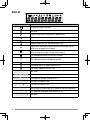
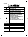
DISPLAY
Icon
Description
Displays the signal strength.
Not used.
Appears when the GPS position is determined.
Appears when Monitor or Squelch Off is activated.
Blinks when an incoming call matches your Optional Signaling.
Appears when the Talk Around function is on.
Lights while scanning or while paused on a channel. Blinks
when scan is temporarily stopped.
Lights when a caller message is in the stack memory. Blinks
when the new message is in the stack memory.
The selected channel is the Priority channel.
Appears when the selected group is programmed as telephone
IDs. Blinks during Auto Telephone search.
The Horn Alert function is on.
The Scrambler/ Encryption function is on.
The Public Address function is on.
Not used.
The current zone is added to the scan sequence.
The External Speaker function is on.
The AUX A function is on.
The AUX B function is on.
The current Channel/Group ID is added to the scan sequence.
The Operator Selectable Tone function is on.
Not used.
4
PROGRAMMABLE FUNCTIONS
The , , , ,
, S, A, <B, C>, and ■ keys can be programmed with the functions
listed below. Ask your dealer for details on these functions.
•
•
•
•
•
•
•
•
•
•
•
•
•
•
•
•
•
•
•
•
•
•
•
•
•
•
•
•
•
•
•
•
None
2-tone 1, 10
Auto Telephone 2
Autodial
Autodial Programming
AUX A
AUX B
Broadcast 3
Call 1 ~ 6
CH/GID Down
CH/GID Recall
CH/GID Up
Channel Entry
CW Message 4
Direct CH/GID 1 ~ 5
Display Format
Emergency 5
External Speaker
Fixed Volume
Forced Search 3
Function
GPS Position Display
Group ID/Channel Entry
Group 6
Group + Short Message 6
Group + Status 6
Home CH/GID
Horn Alert
Individual 6
Individual + Short Message 6
Individual + Status 6
LCD Brightness
•
•
•
•
•
•
•
•
•
•
•
•
•
•
•
•
•
•
•
•
•
•
•
•
•
•
•
•
•
•
•
•
Lone Worker
Maintenance
Monitor 7
Monitor Momentary 7
Operator Selectable Tone 1
Priority-channel Select 8
Public Address
Scan
Scan Delete/Add
Scrambler/ Encryption
Scrambler/ Encryption Code
Selcall 9
Selcall + Short Message 9
Selcall + Status 9
Send the GPS data
Short Message
Site Down 3
Site Lock 3
Site Up 3
Squelch Level 1
Squelch Off 1
Squelch Off Momentary 1
Stack
Status
Talk Around 7
Telephone Disconnect 2
Transceiver Password
Volume Down
Volume Up
Zone Delete/Add
Zone Down
Zone Up
1
Available only for Analog Conventional operation.
Available only for Analog Trunking operation.
3
Available only for NXDN Trunking operation.
4
Available only for NXDN Conventional operation.
5
Emergency can be programmed only on the
key. When assigned, the dealer must set
the key assignment hold to “Enable” and second function as “Emergency”.
6
Available only for NXDN Conventional operation and NXDN Trunking operation.
7
Available only for Analog Conventional, Analog Trunking, and NXDN Conventional
operation.
8
Available only for Analog Conventional and NXDN Conventional operation.
9
Available only for Analog Conventional and Analog Trunking operation.
10
Available only for NX-720H/ NX-720HG/ NX-820H/ NX-820HG.
2
5
BASIC OPERATIONS
SWITCHING POWER ON/ OFF
Press to switch the transceiver ON.
• A beep sounds and the display illuminates.
• If the Transceiver Password function is programmed, “PASSWORD” will appear on the
display.
Press
again to switch the transceiver OFF.
■ Transceiver Password
To enter the password:
1 Press the / key to select a digit.
• When using a microphone DTMF keypad, simply enter the password digits and
proceed to step 4.
2 Press the S or key to accept the entry and move to the next digit.
• Press the A or # key to delete an incorrect digit.
• Press the C> key to delete all.
3 Repeat steps 1 and 2 to enter the entire password.
• The password can contain a maximum of 6 digits.
4 Press the S or key to confirm the entered password.
• If you enter an incorrect password, an error tone sounds and the transceiver
remains locked.
ADJUSTING THE VOLUME
Press the [Volume Up] key to increase the volume. Press the [Volume Down] key to
decrease the volume.
If Squelch Off has been programmed onto a key, you can use that function to listen to
background noise while adjusting the volume level.
SELECTING A ZONE AND CHANNEL/GROUP ID
Select the desired zone and channel/group ID using the keys programmed as [Zone Up]/
[Zone Down] and [CH/GID Up]/ [CH/GID Down].
•
You can program names for zones and channels/group IDs with up to 10 characters.
•
If the Voice Announce function has been set up by your dealer, an audio voice will
announce the new zone, channel and group number when changing the zone, channel,
and/or group.
TRANSMITTING
1
Select the desired zone and channel/group ID.
2
Press the key programmed as [Monitor] or [Squelch Off] to check whether or not the
channel is free.
6
•
3
If the channel is busy, wait until it becomes free.
Press the PTT switch and speak into the microphone. Release the PTT switch to
receive.
• For best sound quality, hold the transceiver approximately 1.5 inches (3 ~ 4 cm)
from your mouth.
■ Making Group Calls (Digital)
If a key has been programmed as [Group], you can select a group ID from the list to
make a call to those parties on a Conventional channel.
To select a group ID:
1 Press the key programmed as [Group].
2 Press the / key to select a group ID/name from the list.
3 Press and hold the PTT switch to make the call.
• Speak into the transceiver as you would during a normal transmission.
■ Making Individual Calls (Digital)
If a key has been programmed with [Individual], you can make calls to specific
persons.
1 Press the key programmed as [Individual].
2 Press the / key to select a unit ID from the list.
• When using a microphone DTMF keypad, you can enter a unit ID directly.
3 Press and hold the PTT switch to make the call.
• Speak into the transceiver as you would during a normal transmission.
RECEIVING
Select the desired zone and channel. If signaling has been programmed on the selected
channel, you will hear a call only if the received signal matches your transceiver settings.
Note: Signaling allows your transceiver to code your calls. This will prevent you from listening to
unwanted calls. Refer to “SIGNALING” on page 15 for details.
■ Receiving Group Calls (Digital)
When you receive a group call on a Conventional channel and the received group ID
matches the ID set up on your transceiver, you can hear the caller’s voice.
When you receive a group call on a Trunking channel, the transceiver automatically
switches to the communications channel to receive the call.
■ Receiving Individual Calls (Digital)
When you receive an individual call, a ringing tone will sound and the caller’s ID will
appear on the display. To respond to the call, press and hold the PTT switch and speak
into the transceiver as you would during a normal transmission.
7
SCAN
Scan monitors for signals on the transceiver channels. While scanning, the transceiver
checks for a signal on each channel and only stops if a signal is present.
To begin scanning, press the key programmed as [Scan].
indicator appears.
• The
• When a signal is detected on a channel, Scan pauses at that channel. The transceiver
will remain on the busy channel until the signal is no longer present, at which time Scan
resumes.
To stop scanning, press the [Scan] key again.
Note: To use Scan, there must be at least 2 channels in the scan sequence.
TEMPORARY CHANNEL LOCKOUT
During scan, you can temporarily remove specific channels from the scanning sequence by
selecting them and pressing the key programmed as [Scan Delete/Add].
• The channel is no longer scanned. However, when scanning is ended and restarted,
the channels are reset and deleted channels will again be in the scanning sequence.
PRIORITY SCAN
If a Priority channel has been programmed, the transceiver will automatically change to the
Priority channel when a call is received on that channel, even if a call is being received on
a normal channel.
•
The
indicator appears when the selected channel is the Priority channel (depending
on dealer setting).
SCAN REVERT
The Scan Revert channel is the channel selected when you press the PTT switch to
transmit during scan. Your dealer can program one of the following types of Scan Revert
channels:
• Selected: The last channel selected before scan.
• Selected + Talkback: Same as “Selected”, plus you can respond to calls on the
channel at which scan is paused.
• Priority: The Priority channel.
• Priority + Talkback: Same as “Priority”, plus you can respond to calls on the channel
at which scan is paused.
• Last Called + Selected: The last channel on which you receive a call.
8
SCAN DELETE/ADD
You can add and remove zones and/or channels/group IDs to and from your scan list.
1
Select your desired zone and/or channel/group ID.
2
Press the key programmed as [Zone Delete/Add] (to add/remove zones) or [Scan
Delete/Add] (to add/remove channels/group IDs).
• You can also press and hold the key programmed as [Scan Delete/Add] to add/
remove zones.
•
When a channel/Group ID is added to scan, the
the display.
•
When a zone is added to scan, the
icon appears on
icon appears on the display.
9
FleetSync: ALPHANUMERIC 2-WAY PAGING FUNCTION
FleetSync is an Alphanumeric 2-way Paging Function, and is a protocol owned by
JVC KENWOOD Corporation.
Note: This function is available only in analog operation.
SELCALL (SELECTIVE CALLING)
A Selcall is a voice call to a station or group of stations.
■ Transmitting
1
2
3
4
Select your desired zone and channel.
Press the key programmed as [Selcall] to enter Selcall mode.
Press the / key to select the station you want to call.
Press the PTT switch and begin your conversation.
■ Receiving
An alert tone will sound and the transceiver will enter Selcall mode. The calling station’s
ID will appear when a Selcall is received. You can respond to the call by pressing the
PTT switch and speaking into the microphone.
■ Identification Codes
An ID code is a combination of a 3-digit Fleet number and a 4-digit ID number. Each
transceiver has its own ID.
• Enter a Fleet number (100 ~ 349) to make a group call.
• Enter an ID number (1000 ~ 4999) to make an individual call in your fleet.
• Enter a Fleet number to make a call to all units in the selected fleet (Fleet call).
STATUS MESSAGE
You can send and receive 2-digit Status messages which may be decided in your talk
group. Messages can contain up to 16 alphanumeric characters. Status messages range
from 10 to 99 (80 ~ 99 are reserved for special messages).
A maximum of 15 received messages (combined status messages and short messages)
can be stored in the stack memory of your transceiver.
■ Transmitting
1
2
3
4
10
Select your desired zone and channel.
Press the key programmed as [Status] to enter Status mode (proceed to step 5) or
[Selcall + Status] to enter Selcall mode (proceed to step 3).
Press the / key to select the station you want to call.
• If Manual Dialing is enabled, you can enter a station ID by using the microphone
DTMF keypad by pressing and holding the S or key. Repeat this process
until the entire ID is entered.
Press the S or key to enter Status mode.
5
6
Press the / key to select the status you want to transmit.
• If Manual Dialing is enabled, you can enter a station ID by using the microphone
DTMF keypad (refer to step 3, above).
Press the PTT switch to initiate the call.
• “COMPLETE” appears on the display when the status has been successfully
transmitted.
■ Receiving
A calling ID or text message will appear when a Status call is received. Press any key
to return to normal operation.
■ Reviewing Messages in the Stack Memory
1
Press the key programmed as [Stack], or press and hold the key programmed as
[Selcall], [Status], or [Selcall + Status] to enter Stack mode.
• The last received message is displayed.
2 Press the / key to select the desired message.
• Message types are identified as follows:
ID: Caller ID, ST: Status Message, ME: Short Message
• Press and hold the S or key for 1 second to cycle the display information as
follows:
ID Name > Status/Short Message > CH/GID
3 Press the
key to return to normal operation.
• To delete the selected message, press the A or # key. To confirm the deletion,
Press the S or key.
• To delete all messages, press and hold the A or # key for 1 second. To confirm
the deletion, Press the S or key.
SHORT MESSAGES
This transceiver can receive short data messages which contain a maximum of 48
characters.
• Received short messages are displayed the same as Status messages. A maximum of
15 received messages (combined status messages and short messages) can be stored
in the stack memory of your transceiver.
GPS REPORT
GPS data can be manually transmitted by pressing the key programmed as [Send the
GPS data]. If set up by your dealer, GPS data may be automatically transmitted at a
preset time interval.
• When using the NX-720HG/ NX-820HG/ NX-920G, you must connect a KRA-40 GPS
antenna.
• When using the NX-720H/ NX-820H/ NX-920, you must connect an external GPS unit.
• When the power is turned ON and/or the reception condition of the GPS satellite is
poor, positioning completion time may take longer.
11
TRUNKING CALLS (ANALOG)
PLACING A DISPATCH CALL
1
Select the desired zone and channel/group ID.
2
Press and hold the PTT switch.
3
If the “PTT Proceed” tone sounds, communication is possible; start speaking into the
microphone. Release the PTT switch to receive.
• For best sound quality at the receiving station, hold the microphone approximately
1.5 inches (3 ~ 4 cm) from your mouth.
• Your dealer can deactivate the Proceed PTT tone, if necessary. Ask your dealer for
details.
RECEIVING A DISPATCH CALL
1
When a dispatch call is received, the transceiver will automatically change to the
correct group ID and you will hear the call.
2
Readjust the volume as necessary.
PLACING A TELEPHONE CALL
1
Select the desired zone and channel/group ID.
2
Press and hold the PTT switch for approximately 1 second to ensure a connection.
• Confirm that there is a dial tone after releasing the PTT switch.
3
Alternatively, press the key programmed as [Auto Telephone] to automatically search
for a Telephone Repeater.
• “AUTO TEL” appears on the display and the
icon blinks.
• When the transceiver connects to a telephone line, a dial tone sounds, the
icon
appears on the display, and the transceiver enters the Off Hook state.
4
Place the call, following the instructions for making a DTMF call, starting on page 9.
5
When the called party responds, press the PTT switch and speak into the microphone.
Release the PTT switch to receive.
• Only one person can speak at a time.
RECEIVING A TELEPHONE CALL
1
When a telephone call is received, the transceiver will automatically change to the
correct group ID and you will hear the call.
• A ringer tone will sound when a call is received.
2
Press and hold the PTT switch to speak, and release it to receive.
• Only one person can speak at a time.
DISCONNECT WITH TELEPHONE
To end the call, press the # key or the key programmed as [Telephone Disconnect] while
communicating.
12
DTMF (DUAL TONE MULTI FREQUENCY) CALLS
MANUAL DIALING
1
Press and hold the PTT switch.
2
Enter the desired digits using the microphone DTMF keypad.
• If you release the PTT switch, transmit mode will end even if the complete number
has not been sent.
• If the Keypad Auto PTT function has been enabled by your dealer, you do not need
to press the PTT switch to transmit; you can make the call simply by pressing the
microphone DTMF keys.
■ Store & Send
1
2
3
Press the key programmed as [Autodial].
Enter up to 30 digits using the microphone DTMF keypad.
Press the PTT switch to make the call.
AUTODIAL
Autodial allows you to quickly call DTMF numbers that have been programmed onto your
transceiver.
1
Press the key programmed as [Autodial].
• The first entry in the Autodial list appears on the display.
2
Press the / key to select an autodial list number.
• You can also enter a number from 01 ~ 32 directly using the microphone DTMF
keypad.
3
Press the PTT switch to make the call.
■ Storing an Autodial Entry
1
2
3
4
5
Press the key programmed as [Autodial Programming].
Press the / key to select a memory location number.
Press the S or key to enter a name for the list number.
Press the / key to select a digit.
Press the C> key to accept the entered digit and move the cursor to the right.
• Press the A or # key to delete an incorrect digit. Press and hold the A or # key
to delete all digits.
6 Repeat steps 4 and 5 to enter the entire name.
7 Press the S or key to accept the name and enter a number.
8 Press the / key to select a digit.
• You can also enter digits directly using the microphone DTMF keypad.
9 Press the S or key to accept the entered digit.
• Press the A or # key to delete an incorrect digit. Press and hold the A or # key
to delete all digits.
10 Repeat steps 8 and 9 to enter the entire number.
11 Press the S or key to accept the number and store the entry.
13
■ Removing an Autodial Entry
1
2
3
4
Press the key programmed as [Autodial Programming].
Press the / key to select a memory location number.
Press the A or # key.
• “DELETE” appears on the display.
• Additionally, you can press and hold the A or # key to delete all entries.
Press the S or key to confirm the deletion.
REDIALING
1
Press the key programmed as [Autodial].
2
Press the key, then press the 0 key.
• If there is no data in the redial memory, an error tone will sound.
3
Press the PTT switch to make the call.
STUN
This function is used when a transceiver is stolen or lost. When the transceiver receives a
call containing a stun code, the transceiver becomes disabled. The stun code is cancelled
when the transceiver receives a call with a revive code.
• “STUN” appears on the display while the transceiver is stunned.
14
ADVANCED OPERATIONS
EMERGENCY CALLS
If your transceiver has been programmed with the Emergency function, you can make
emergency calls.
1
Press and hold the key programmed as [Emergency].
• Ask your dealer for the length of time necessary to hold this key before the
transceiver enters Emergency mode.
• When the transceiver enters Emergency mode, it will change to the Emergency
channel and begin transmitting based on how it is set up by your dealer.
2
To exit Emergency mode, press the [Emergency] key again.
• If the Emergency mode completes a preset number of cycles, Emergency mode will
automatically end and the transceiver will return to the zone and channel that was in
use before Emergency mode was entered.
Note:
◆ Your dealer can set the transceiver to emit a tone when transmitting in Emergency mode.
◆ Your dealer can set the transceiver to emit tones and received signals as normal, or mute the
speaker during Emergency operation.
SCRAMBLER (ANALOG) / ENCRYPTION (DIGITAL)
■ Secure (Encrypted) Transmission
Press the key programmed as [Scrambler/ Encryption] to switch the transceiver to
secure (encrypted) transmission.
•
•
The icon appears on the display.
Pressing the PTT switch after the Scrambler or Encryption function has been turned
ON encrypts the transmitted signal.
■ Selecting the Scrambler Code or Encryption Key
1
2
Press the key programmed as [Scrambler/ Encryption Code] to enter Code or Key
Selection mode.
Press the / key to increase or decrease the code or key.
• There are 16 available Scrambler codes or Encryption keys (1 ~ 16).
SIGNALING
■ Quiet Talk (QT)/ Digital Quiet Talk (DQT)
Your dealer may have programmed QT or DQT signaling on your transceiver channels.
A QT tone/ DQT code is a sub-audible tone/code which allows you to ignore (not hear)
calls from other parties who are using the same channel.
Operator Selectable Tone (OST)
If a key has been programmed with [OST], you can reprogram the QT/DQT settings on
each of your channels.
15
1
2
3
4
Select your desired channel.
Press and hold the key programmed as [OST] for 1 second.
Press the / key to select your desired tone or code.
• Your dealer can set up to 40 tones/codes.
When you have finished operating using OST, press the [OST] key again to turn the
OST function OFF.
■ Radio Access Number (RAN)
RAN is a signaling system designed for digital radio communications.
When a channel is set up with a RAN, squelch will only open when a call containing
a matching RAN is received. If a call containing a different RAN is made on the same
channel you are using, you will not hear the call. This allows you to ignore (not hear)
calls from other parties who are using the same channel.
■ Optional Signaling
Your dealer may also program several types of optional signaling for your transceiver
channels.
2-tone Signaling: 2-tone Signaling opens the squelch only when your transceiver
receives a call containing matching 2 tones (available only for NX-720H/ NX-720HG/
NX-820H/ NX-820HG).
DTMF Signaling: DTMF Signaling opens the squelch only when the transceiver
receives a call containing a matching DTMF code.
FleetSync Signaling: Refer to “SELCALL (SELECTIVE CALLING)” on page 10.
NXDN ID Signaling: NXDN ID is an optional signaling system available only for digital
communications.
MONITOR/ SQUELCH OFF
You can use the key programmed as [Monitor] or [Squelch Off] to listen to weak signals
that you cannot hear during normal operation and to adjust the volume when no signals are
present on your selected channel.
•
The
icon appears on the display while Monitor or Squelch Off is activated.
Your dealer can program a key with one of four Monitor/Squelch Off functions:
• Monitor: Press to deactivate QT, DQT, DTMF, 2-tone, or FleetSync Signaling. Press
again to return to normal operation.
• Monitor Momentary: Press and hold to deactivate QT, DQT, DTMF, 2-tone or
FleetSync Signaling. Release to return to normal operation.
• Squelch Off: Press to hear background noise. Press again to return to normal
operation.
• Squelch Off Momentary: Press and hold to hear background noise. Release to return
to normal operation.
■ Squelch Level
If a key has been programmed as [Squelch Level], you can readjust your transceiver’s
squelch level:
1
16
Press the key programmed as [Squelch Level].
2
3
• The current squelch level appears on the display.
Press the / key to select your desired squelch level from 0 to 9.
Press the S or key to store the new setting.
SIGNAL STRENGTH INDICATOR
The signal strength indicator displays the strength of received calls. No icon appears when
no signal is available.
Strong
Sufficient
Weak
Very weak
flashes when out of range (NXDN Trunking only).
PUBLIC ADDRESS (PA)
The PA system can only be used with an external speaker.
1
Press the key programmed as [Public Address] to activate the Public Address
function.
2
Press and hold the PTT switch, then speak into the microphone to make your address
through the external speaker.
3
Press the [Public Address] key again to exit Public Address.
•
The
icon appears on the display.
HORN ALERT
When a call is received that matches the optional signaling set up on your transceiver,
Horn Alert causes the vehicle horn or some other external alert to sound. This function
notifies you of a received call when you are away from your vehicle.
To toggle Horn Alert ON and OFF, press they key programmed as [Horn Alert].
•
The
icon momentarily appears on the display when Horn Alert is active.
EXTERNAL SPEAKER
When attaching an external speaker to the transceiver via the KCT-60, press the key
programmed as [External Speaker] to output all received signals through the external
speaker.
•
The
icon appears on the display.
Press the [External Speaker] key again to output all received signals only through the
built-in speaker.
DISPLAY BRIGHTNESS
You can cycle the display brightness between high, low, and off by pressing the key
programmed as [LCD Brightness].
17
BACKGROUND OPERATIONS
TIME-OUT TIMER (TOT)
The Time-out Timer prevents you from using a channel for an extended duration. If you
continuously transmit for a preset time, the transceiver will stop transmitting and an alert
tone will sound. Release the PTT switch.
AUXILIARY PORT
Press the key programmed as [AUX A] or [AUX B] to activate the auxiliary port. The
auxiliary port is used with external devices.
• The
icon appears on the display when the auxiliary A port is active.
• The
icon appears on the display when the auxiliary B port is active.
BUSY CHANNEL LOCKOUT (BCL)
If BCL is set up by your dealer, you will be unable to transmit if the channel is already in
use.
• “BUSY” appears on the display when you press the PTT switch. Use a different
channel or wait until the channel becomes free.
If your dealer has programmed BCL Override for your transceiver, you can override the
BCL by pressing the PTT switch again, immediately after releasing it, when the channel is
busy.
CONTROL CHANNEL HUNT
On digital Trunking channels, the transceiver automatically searches for a control channel.
• While searching for a control channel, the antenna icon will flash and no signals can be
received.
PTT ID
PTT ID is the transceiver unique ID code which is sent each time the PTT switch is pressed
and/or released. (PTT ID can be made only in analog operation.)
COMPANDER
If programmed by your dealer for a channel, the compander will remove excessive noise
from transmitted signals, providing higher clarity of signals. (The compander is used only in
analog operation.)
• Your dealer must set the compander for both the transmit side and the receive side in
order for the compander to operate.
TRANSMIT POWER
Your dealer has programmed a transmit power level for each channel. Power levels can be
high, medium (available only for NX-720H/ NX-720HG/ NX-820H/ NX-820HG), or low.
18
NX-720H
NX-820H
NX-920
NX-720HG
NX-820HG
NX-920G
MODE D’EMPLOI
FRANÇAIS
ÉMETTEUR-RÉCEPTEUR NUMÉRIQUE VHF
ÉMETTEUR-RÉCEPTEUR NUMÉRIQUE UHF
ÉMETTEUR-RÉCEPTEUR NUMÉRIQUE 800MHz
Description de la borne
ACC (Connecteur D-SUB 15 broches)
N° de
broche
Nom de
broche
E/S
1
SB
S
Description
Caractéristiques
Sortie d’alimentation CC (commuté B)
13,6 V ± 15% Max 2 A
Entrée Min : 10,8 V
Entrée Max : 16,0 V
2
IGN
E
Entrée du signal d’allumage
3
SP2/IPA
S
Sortie de haut-parleur/ Sortie de sonorisation
4
4
DETO
S
Sortie audio de détecté RX
200 mVc-c (typ.)
5
DATAI
E
Entrée de données TX
100 k
6
FNC1/TXD
E/S
Programmable/ Données série PC de la Radio
Impédance élevée
7
FNC2/RXD
E/S
Programmable/ Données série PC à la Radio
Impédance élevée
8
FNC3
E/S
Programmable
Impédance élevée
9
FNC4
E/S
Programmable
Impédance élevée
10
FNC5
E/S
Programmable
Impédance élevée
11
FNC6
E/S
Programmable
Impédance élevée
12
50MC
S
Sortie d’alimentation CC
5 V, Max 100 mA
13
HR1
E
Entrée du signal d’avertissement par klaxon
Max 2 A
14
HR2
S
Sortie du signal d’avertissement par klaxon
Max 2 A
15
GND
—
Terre
Terre
Prise de haut-parleur (prise téléphonique 3,5 mm) 4 W/ 4
N° de
broche
Nom de
broche
E/S
Description
Caractéristiques
1
SPO
S
Sortie de haut-parleur externe
4
3
GND
—
Terre
Terre
Connecteur d’entrée CC
N° de
broche
Nom de
broche
E/S
Rouge
B
E
Entrée d’alimentation CC
13,6 V ± 15%
Noir
GND
E
Terre
Terre
Description
Caractéristiques
Prise du microphone
N° de
broche
Nom de
broche
1
MBL
S
Contrôle du rétroéclairage Mic
—
2
SB
S
Sortie d’alimentation CC (commuté B)
13,6 V ± 15%
Terre
Terre
PTT/ Données série PC de la Radio
Impédance élevée
E/S
Description
Caractéristiques
3
GND
—
4
PTT/TXD
E/S
5
ME
—
Mic Terre
Terre
6
MIC
E
Entrée du signal Mic
600
7
HOOK/RXD
E
Données série Support/ PC vers la radio
Impédance élevée
8
DM
E/S
Détection des données Mic
Impédance élevée
Connecteur d’antenne RF
50 d’impédance
Connecteur d’antenne GPS <NX-720HG/ NX-820HG/ NX-920G uniquement>
50 d’impédance
MERCI
Nous sommes heureux que vous ayez choisi KENWOOD pour vos applications mobiles
personnelles.
Ce mode d’emploi ne reprend que le fonctionnement de base de votre radio mobile. Renseignezvous auprès de votre revendeur pour de plus amples informations relatives aux fonctions
personnalisées qui ont pu être ajoutées à votre radio.
AVIS AUX UTILISATEURS
◆ Une loi gouvernementale interdit l’usage sans licence des émetteurs radio sur les territoires
régis par cette autorité gouvernementale.
◆ Une utilisation illégale est passible d’amende ou d’emprisonnement.
◆ Pour l’entretien et la réparation, confiez l’appareil uniquement à des techniciens qualifiés.
SÉCURITÉ : Il est important que l’opérateur soit au courant des risques usuels associés à
l’exploitation d’un émetteur-récepteur.
AVERTISSEMENT
◆ ATMOSPHÈRES EXPLOSIVES (GAZ, POUSSIÈRE, FUMÉE, etc.)
Mettez l’émetteur-récepteur hors tension lorsque vous faites le plein d’essence ou lorsque vous
garez votre véhicule dans une station-service. Ne transportez pas de bidons d’essence dans
le coffre arrière de votre véhicule si votre émetteur-récepteur est installé dans cette zone.
◆ BLESSURES RÉSULTANT DE LA TRANSMISSION DE FRÉQUENCES RADIO
Ne faites pas fonctionner l’émetteur-récepteur lorsque quelqu’un se trouve à proximité
de ou touche l’antenne, de manière à éviter tout risque de brûlures occasionnées par les
radiofréquences et autres blessures connexes.
◆ DÉTONATEURS DE DYNAMITE
L’exploitation de l’émetteur-récepteur dans un rayon de 150 mètres d’un détonateur de
dynamite pourrait provoquer son explosion. Mettez votre émetteur-récepteur hors tension
lorsque vous êtes dans une zone de dynamitage en cours ou dans un endroit où des panneaux
d’avertissement demandent de mettre les émetteurs-récepteurs hors tension. Si vous
transportez des détonateurs dans votre véhicule, assurez-vous qu’ils se trouvent dans des
contenants métalliques fermés dont l’intérieur est matelassé. N’émettez jamais pendant qu’on
place ou qu’on sort les détonnateurs de leur contenant.
F-i
PRÉCAUTIONS
Veuillez respecter les points suivants afin d’éviter les risques d’incendie, de blessure corporelle
ou d’endommagement de l’émetteur-récepteur.
• Ne tentez pas de configurer l’émetteur-récepteur tout en conduisant, car cela est trop
dangeureux.
• Ne démontez et ne modifiez sous aucun cas l’émetteur-récepteur.
• N’exposez pas l’émetteur-récepteur aux rayons directs du soleil pendant de longues périodes
et ne le placez pas près d’appareils chauffants.
• Si une odeur anormale ou de la fumée est générée par l’émetteur-récepteur, mettez
immédiatement l’émetteur-récepteur hors tension et contactez votre revendeur KENWOOD.
• Il est possible que l’utilisation de l’émetteur-récepteur lors de la conduite soit contraire aux
règles de circulation. Veuillez vérifier et respecter les régulations routières de votre pays.
• N’utilisez pas les options non indiquées par KENWOOD.
ATTENTION
◆ Cet émetteur-récepteur fonctionne uniquement avec un système de 12 V à masse négative!
Vérifiez la polarité et la tension de la batterie du véhicule avant d’installer l’émetteur-récepteur.
◆ Utilisez uniquement le câble d’falimentation CC fourni ou un câble d’alimentation CC
KENWOOD en option.
◆ Ne pas couper et/ou retirer le support de fusible sur le câble d’alimentation CC.
AVERTISSEMENT
Pour la sécurité du passager, et pour éviter que l’émetteur-récepteur ne se détache en cas de collision,
fixez solidement l’émetteur-récepteur en utilisant le support de montage et l’ensemble des vis.
TABLE DES MATIÈRES
POUR DÉMARRER ............................................................................................. 1
FAMILIARISATION AVEC L’APPAREIL .............................................................. 3
FONCTIONS PROGRAMMABLES ..................................................................... 5
FONCTIONNEMENT DE BASE........................................................................... 6
BALAYAGE .......................................................................................................... 8
FleetSync: TÉLÉAVERTISSEUR BIDIRECTIONNEL ALPHANUMÉRIQUE .... 10
APPELS TRUNKING (ANALOGIQUES) ........................................................... 12
APPELS DTMF (DOUBLE TONALITÉ MULTI-FRÉQUENCE).......................... 13
OPÉRATIONS AVANCÉES................................................................................ 15
OPÉRATIONS EN ARRIÈRE-PLAN .................................................................. 18
F-ii
POUR DÉMARRER
Remarque : les instructions suivantes sont destinées à votre revendeur KENWOOD, un centre de
service agréé KENWOOD ou à l’usine de fabrication.
ACCESSOIRES FOURNIS
Déballez soigneusement l’émetteur-récepteur. Nous recommandons que vous identifiez les
articles de la liste ci-dessous avant de vous débarrasser des matériaux d’emballage.
Si un article manque ou a été endommagé pendant l’expédition, remplissez immédiatement un
formulaire de plainte auprès du transporteur.
Câble d’alimentation CC (avec fusibles) . . . . . . . . . . . . . . . . . . . . . . . . . . . . . . . . . . . . . . . . . . . . . 1
• Fusible 15 A . . . . . . . . . . . . . . . . . . . . . . . . . . . . . . . . . . . . . . . . . . . . . . . . . . . . . . . . . . . . . . . 2
Support de montage . . . . . . . . . . . . . . . . . . . . . . . . . . . . . . . . . . . . . . . . . . . . . . . . . . . . . . . . . . . . 1
Ensemble de vis
• Vis taraudeuse 5 x 16 mm . . . . . . . . . . . . . . . . . . . . . . . . . . . . . . . . . . . . . . . . . . . . . . . . . . . . 4
• Vis à tête hexagonale et rondelle M4 x 6 mm . . . . . . . . . . . . . . . . . . . . . . . . . . . . . . . . . . . . . 4
• Rondelle à ressort . . . . . . . . . . . . . . . . . . . . . . . . . . . . . . . . . . . . . . . . . . . . . . . . . . . . . . . . . . 4
• Rondelle ordinaire . . . . . . . . . . . . . . . . . . . . . . . . . . . . . . . . . . . . . . . . . . . . . . . . . . . . . . . . . . 4
Microphone (avec câble)
• KMC-35 . . . . . . . . . . . . . . . . . . . . . . . . . . . . . . . . . . . . . . . . . . . . . . . . . . . . . . . . . . . . . . . . . . 1
Crochet à microphone (avec vis taraudeuses 4 x 16 mm) . . . . . . . . . . . . . . . . . . . . . . . . . . . . . . . 1
Mode d’emploi . . . . . . . . . . . . . . . . . . . . . . . . . . . . . . . . . . . . . . . . . . . . . . . . . . . . . . . . . . . . . . . . 1
PRÉPARATION
AVERTISSEMENT
Divers équipements électroniques de votre véhicule peuvent mal fonctionner s’ils ne sont pas
correctement protégés contre l’énergie radiofréquence produite pendant l’émission. Par exemple,
l’injection électronique, le dispositif anti-blocage de frein et le régulateur de vitesse automatique. Si votre
véhicule contient de tels équipements, consultez le revendeur de votre véhicule et demandez-lui son aide
pour déterminer s’ils fonctionneront normalement pendant une émission.
■ Connexion du câble d’alimentation
ATTENTION
Cet émetteur-récepteur fonctionne uniquement avec un système de 12 V à masse négative! Vérifiez
la polarité et la tension de la batterie du véhicule avant d’installer l’émetteur-récepteur.
1
Vérifiez s’il existe déjà un trou placé de façon pratique dans le pare-feu, à travers lequel
le câble d’alimentation peut être passé.
• S’il n’y a pas de trou, utilisez un trépan pour percer un trou, puis installez un joint en
caoutchouc.
2
Faites passer le câble d’alimentation à travers le pare-feu jusqu’au compartiment du
moteur.
3
Connectez le fil rouge à la borne positive (+) de la batterie et le fil noir à la borne
négative (–) de la batterie.
• Placez le fusible aussi près que possible de la batterie.
Enroulez le câble en trop et fixez-le avec une bande de retenue.
4
F-1
•
Assurez-vous de laisser suffisamment de jeu aux câble de façon à ce que l’émetteurrécepteur puisse être retiré pour réparation tout en restant connecté à l’alimentation.
■ Installation de l’émetteur-récepteur
AVERTISSEMENT
Pour la sécurité du passager, et pour éviter que l’émetteur-récepteur ne se détache en cas de collision,
fixez solidement l’émetteur-récepteur en utilisant le support de montage et l’ensemble des vis.
Remarque : Avant d’installer l’émetteur-récepteur, vérifiez jusqu’où iront les vis de montage sous
la surface. Quand vous percez des trous de montage, faites attention de ne pas endommager le
câblage ou des pièces du véhicule.
1
Marquez la position des trous sur le tableau de bord, en utilisant le support de montage
comme repère. En utilisant une mèche de 4,2 mm, percez les trous, puis fixez le support
de montage en utilisant les vis fournies.
• Montez l’émetteur-récepteur dans un endroit facile à atteindre pour l’utilisateur et où
il y a suffisamment d’espace à l’arrière de l’émetteur-récepteur pour les connexions.
2
Connectez l’antenne et le câble d’alimentation fourni à l’émetteur-récepteur.
3
Faites glisser l’émetteur-récepteur dans le support de montage et fixez-le en utilisant les
vis à tête hexagonale fournies.
4
Montez le crochet à microphone dans un endroit facile d’accès pour l’utilisateur.
• Le microphone et le câble du microphone doivent être montés dans un endroit où ils
ne gêneront pas la conduite en toute sécurité du véhicule.
ATTENTION
Lors du remplacement du fusible dans le câble d’alimentation CC, assurez-vous de le remplacer par
un fusible de la même valeur. Ne le remplacez jamais par un fusible d’une valeur supérieure.
Rondelle
ordinaire
Vis à tête hexagonale
M4 x 6 mm
Rondelle
à ressort
Microphone
5 x 16 mm
Vis taraudeuse
Connecteur
d’antenne RF
Support de montage
Connecteur d’entrée
de l’alimentation
Câble noir (–)
Câble rouge (+)
Câble d’alimentation CC
Fusible
F-2
Batterie de
véhicule de
12 V
FAMILIARISATION AVEC L’APPAREIL
VUES AVANT ET ARRIÈRE
ab
c
d ef
a
g
j
h
k
i
l
m
n
Commutateur (d’alimentation)
Appuyez pour mettre sous ou hors tension l’émetteur-récepteur.
b Touches /
Appuyez pour activer leurs fonctions programmables {page 5}.
c Touches /
Appuyez pour activer leurs fonctions programmables {page 5}.
d Indicateur TX/RX
S’allume en rouge lors de la transmission et en vert lors de la réception d’un signal. Clignote
en orange lors de la réception d’un appel de signalisation optionnelle.
e Prise de microphone
Insérez la fiche du microphone dans cette prise.
f Indicateur d’état
S’allume en bleu pendant un mode spécifié, sur base de la programmation du revendeur.
/ S / A / <B / C> / ■
g Touches
Appuyez pour activer leurs fonctions programmables {page 5}.
h Haut-parleur
Haut-parleur interne.
i Commutateur PTT
Appuyez sur ce commutateur puis, parlez dans le microphone pour appeler une station.
j Connecteur d’antenne RF
Raccordez l’antenne RF à ce connecteur.
k Connecteur ACC
Raccordez l’ACC à ce connecteur, via le KCT-60.
l Prise pour haut-parleur externe
Raccordez un haut-parleur externe à cette prise.
m Connecteur d’antenne GPS <NX-720HG/ NX-820HG/ NX-920G uniquement>
Raccordez l’antenne GPS KRA-40 à ce connecteur.
n Connecteur d’entrée de l’alimentation
Raccordez le câble d’alimentation CC à ce connecteur.
F-3
AFFICHEUR
Icône
Description
Affiche la puissance du signal.
Non utilisé.
Apparaît lorsque la position GPS est définie.
Apparaît lorsque Surveillance ou Silencieux désactivé est activé.
Clignote lorsqu’un appel entrant correspond à votre signalisation
optionnelle.
Apparaît lorsque la fonction Talk Around est activée.
S’allume pendant le balayage ou alors qu’il est arrêté sur un canal.
Clignote lorsque le balayage est temporairement arrêté.
S’allume lorsqu’un message d’appelant est dans la pile mémoire.
Clignote lorsque le nouveau message est dans la pile mémoire.
Le canal sélectionné est le Canal prioritaire.
Apparaît lorsque le groupe sélectionné est programmé en tant
qu’ID de téléphone. Clignote pendant la recherche Téléphone
automatique.
La fonction Avertissement par klaxon est activée.
La fonction Brouilleur/ Codage est activée.
La fonction Sonorisation est activée.
Non utilisé.
La zone actuelle est ajoutée à la séquence de balayage.
La fonction Haut-parleur externe est activée.
La fonction AUX A est activée.
La fonction AUX B est activée.
Le canal/ID de groupe actuel est ajouté à la séquence de balayage.
La fonction Tonalité sélectionnable par l’opérateur est activée.
Non utilisé.
F-4
FONCTIONS PROGRAMMABLES
Les touches , , , , , S, A, <B, C> et ■ peuvent être programmées avec les fonctions
énumérées ci-dessous. Demandez à votre revendeur plus de détails concernant ces fonctions.
•
•
•
•
•
•
•
•
•
•
•
•
•
•
•
•
•
•
•
•
•
•
•
•
•
•
•
•
•
•
•
1
2
3
4
5
6
7
8
9
10
Aucune
2 tonalités 1, 10
Téléphone automatique 2
Composition automatique
Programmation de composition
automatique
AUX A
AUX B
Diffusion 3
Appel 1 ~ 6
CH/GID bas
CH/GID rappel
CH/GID haut
Saisie du canal
Message CW 4
Direct CH/GID 1 ~ 5
Format d’affichage
Urgence 5
Haut-parleur externe
Volume fixe
Recherche forcée 3
Fonction
Affichage de la position du GPS
ID de groupe/Saisie du canal
Groupe 6
Groupe + Message court 6
Groupe + État 6
CH/GID principal
Avertissement par klaxon
Individuel 6
Individuel + Message court 6
Individuel + État 6
•
•
•
•
•
•
•
•
•
•
•
•
•
•
•
•
•
•
•
•
•
•
•
•
•
•
•
•
•
•
•
•
•
Éclat LCD
Travailleur seul
Entretien
Surveillance 7
Surveillance momentanée 7
Tonalité sélectionnable par l’opérateur 1
Sélection canal prioritaire 8
Sonorisation
Balayage
Suppr./ajout au balayage
Brouilleur/ codage
Code brouilleur/ codage
Selcall 9
Selcall + Message court 9
Selcall + État 9
Émettre les données de GPS
Message court
Site bas 3
Verrouillage de site 3
Site haut 3
Niveau du silencieux 1
Silencieux désactivé 1
Silencieux désactivé momentané 1
Pile
État
Talk Around 7
Débranchement du téléphone 2
Mot de passe émetteur-récepteur
Volume bas
Volume haut
Effacement/ajout de zone
Zone bas
Zone haut
Disponible uniquement pour une utilisation analogique conventionnelle.
Disponible uniquement pour un fonctionnement trunking analogique.
Disponible uniquement pour un fonctionnement trunking NXDN.
Disponible uniquement pour un fonctionnement conventionnel NXDN.
L’urgence peut uniquement être programmée sur la touche . Lorsqu’elle est attribuée, le
revendeur doit régler l’attribution de touche sur “Activer” et la seconde fonction sur “Urgence”.
Disponible uniquement pour un fonctionnement conventionnel NXDN et un fonctionnement
trunking NXDN.
Disponible uniquement pour un fonctionnement analogique conventionnel, analogique
trunking et NXDN conventionnel.
Disponible uniquement pour un fonctionnement analogique conventionnel et NXDN
conventionnel.
Disponible uniquement pour un fonctionnement conventionnel analogique et analogique
trunking.
Disponible uniquement pour NX-720H/ NX-720HG/ NX-820H/ NX-820HG.
F-5
FONCTIONNEMENT DE BASE
MISE SOUS/HORS TENSION
Appuyez sur
pour mettre l’émetteur-récepteur sous tension.
• Un bip retentit et l’afficheur s’allume.
• Si la fonction Mot de passe émetteur-récepteur est programmée, “PASSWORD” apparaîtra
sur l’afficheur.
Appuyez à nouveau sur
pour mettre l’émetteur-récepteur hors tension.
■ Mot de passe émetteur-récepteur
Pour saisir le mot de passe:
1
Appuyez sur la touche / pour sélectionner un chiffre.
• Lors de l’utilisation d’un clavier DTMF à microphone, saisissez simplement les
chiffres du mot de passe et passez à l’étape 4.
2
Appuyez sur la touche S ou pour accepter la saisie et passer au nouveau chiffre.
• Appuyez sur la touche A ou # pour effacer un chiffre incorrect.
• Appuyez sur la touche C> pour tout effacer.
3
Répétez les étapes 1 et 2 pour saisir tout le mot de passe.
• Le mot de passe peut contenir 6 chiffres au maximum.
4
Appuyez sur la touche S ou pour confirmer le mot de passe saisi.
• Si vous saisissez un mot de passe incorrect, une tonalité d’erreur est émise et
l’émetteur-récepteur reste verrouillé.
RÉGLAGE DU VOLUME
Appuyez sur la touche [Volume haut] pour augmenter le volume. Appuyez sur la touche
[Volume bas] pour baisser le volume.
Si Silencieux désactivé a été programmé sur une touche, vous pouvez utiliser cette fonction
pour écouter le bruit de fond pendant le réglage du niveau du volume.
SÉLECTION D’UNE ZONE ET D’UN CANAL/ ID DE GROUPE
Sélectionnez la zone souhaitée et le canal/ID de groupe à l’aide des touches programmées pour
[Zone haut]/ [Zone bas] et [CH/GID haut]/ [CH/GID bas].
•
Vous pouvez programmer les noms pour des zones et des canaux/ID de groupe comportant
au maximum 10 caractères.
•
Lors du changement de la zone, du canal et/ou du groupe, une voix audio annonce le
nouveau numéro de zone, de canal et de groupe.
TRANSMISSION
1
Sélectionnez la zone et le canal/ID de groupe souhaités.
2
Appuyez sur la touche programmée pour la fonction [Surveillance] ou [Silencieux
désactivé] pour vérifier si le canal est libre ou non.
• Si le canal est occupé, attendez qu’il se libère.
3
Appuyez sur le commutateur PTT et parlez dans le microphone. Relâchez le commutateur
PTT pour recevoir.
F-6
•
Pour une meilleure qualité du son, tenez le microphone à environ 1,5 pouces (3 à 4 cm)
de votre bouche.
■ Émettre des appels de groupe (numériques)
Si une touche a été programmée pour la fonction [Groupe], vous pouvez sélectionner une
ID de groupe depuis la liste pour appeler ces autres parties sur un canal conventionnel.
Pour sélectionner une ID de groupe:
1
Appuyez sur la touche programmée pour la fonction [Groupe].
2
Appuyez sur la touche
3
Appuyez sur le commutateur PTT et maintenez-le enfoncé pour émettre un appel.
• Parlez dans l’émetteur-récepteur comme lors d’une transmission normale.
/
pour sélectionner une ID de groupe/un nom dans la liste.
■ Émettre des appels individuels (numériques)
Si une touche a été programmée pour la fonction [Individuel], vous pouvez émettre des
appels à des personnes en particulier.
1
Appuyez sur la touche programmée pour la fonction [Individuel].
2
Appuyez sur la touche / pour sélectionner une ID d’unité dans la liste.
• Si vous utilisez un clavier DTMF à microphone, vous pouvez saisir directement une
ID d’unité.
3
Appuyez sur le commutateur PTT et maintenez-le enfoncé pour émettre un appel.
• Parlez dans l’émetteur-récepteur comme lors d’une transmission normale.
RÉCEPTION
Sélectionnez la zone et le canal souhaités. Si la signalisation a été programmée sur le canal
sélectionné, vous n’entendrez un appel que si le signal reçu correspond aux réglages de votre
émetteur-récepteur.
Remarque: grâce à la signalisation, votre émetteur-récepteur peut coder vos appels. Cela vous
permet de ne pas écouter les appels non désirés. Pour de plus amples détails, reportez-vous à
“SIGNALISATION” en page 15.
■ Recevoir des appels de groupe (numériques)
Lorsque vous recevez un appel de groupe sur un canal conventionnel et que l’ID de groupe
reçue correspond à celle qui est configurée sur votre émetteur-récepteur, vous pouvez
entendre la voix de l’appelant.
Lorsque vous recevez un appel de groupe sur un canal trunking, l’émetteur-récepteur passe
automatiquement sur le canal de communications pour recevoir l’appel.
■ Recevoir des appels individuels (numériques)
Lorsque vous recevez un appel individuel, une sonnerie est émise et l’ID de l’appelant
s’affiche. Pour répondre à l’appel, appuyez et maintenez enfoncé le commutateur PTT et
parlez dans l’émetteur-récepteur comme lors d’une transmission normale.
F-7
BALAYAGE
Le balayage surveille les signaux sur les canaux de l’émetteur-récepteur. Durant le balayage,
l’émetteur-récepteur recherche un signal sur chaque canal et s’arrête uniquement si un signal
est présent.
Pour commencer le balayage, appuyez sur la touche programmée pour la fonction [Balayage].
apparaît.
• L’indicateur
• Lorsqu’un signal est détecté sur un canal, le balayage s’arrête momentanément sur ce
canal. L’émetteur-récepteur restera sur le canal occupé jusqu’à ce que le signal ne soit plus
présent, moment auquel le Balayage reprend.
Pour arrêter le balayage, appuyez à nouveau sur la touche [Balayage].
Remarque: pour utiliser Balayage, 2 canaux minimum doivent se trouver dans la séquence de balayage.
BLOCAGE DE CANAL TEMPORAIRE
Pendant le balayage, vous pouvez temporairement retirer des canaux spécifiques de la
séquence de balayage en les sélectionnant et en appuyant sur la touche programmée pour la
fonction [Suppr./ajout au balayage].
• Le canal n’est plus balayé. Cependant, lorsque le balayage est terminé et qu’il reprend,
les canaux sont réinitialisés et les canaux supprimés seront de nouveau inclus dans la
séquence de balayage.
BALAYAGE PRIORITAIRE
Si un Canal prioritaire a été programmé, l’émetteur-récepteur passe automatiquement sur
le canal prioritaire quand un appel est reçu sur ce canal, même si un appel est en cours de
réception sur un canal normal.
•
apparaît lorsque le canal sélectionné est le canal prioritaire (en fonction du
L’indicateur
réglage du revendeur).
BALAYAGE INVERSE
Le canal de balayage inverse est le canal sélectionné lorsque vous appuyez sur le commutateur
PTT pour transmettre pendant le balayage. Votre revendeur peut programmer l’un des types de
canaux de balayage inverse suivants:
• Sélectionné: le dernier canal sélectionné avant le balayage.
• Sélectionné + Talkback: identique à “Sélectionné”, en plus, vous pouvez répondre à des
appels sur le canal sur lequel le balayage est momentanément arrêté.
• Priorité: le canal prioritaire.
• Priorité + Talkback: identique à “Priorité”, en plus, vous pouvez répondre à des appels sur
le canal sur lequel le balayage est momentanément arrêté.
• Dernier reçu + Sélectionné: le dernier canal sur lequel vous recevez un appel.
F-8
SUPPR./AJOUT AU BALAYAGE
Vous pouvez ajouter et enlever des zones et/ou des canaux/ID de groupe à et de la liste de
balayage.
1
Sélectionnez la zone et/ou le canal/ID de groupe souhaités.
2
Appuyez sur la touche programmée pour la fonction [Effacement/ajout de zone] (pour
ajouter/effacer des zones) ou [Suppr./ajout au balayage] (pour ajouter/effacer des canaux/
ID de groupe).
• Vous pouvez également appuyez sur la touche programmée pour la fonction [Suppr./
ajout au balayage] et maintenez-la enfoncée pour ajouter/supprimer des zones.
•
Lorsqu’un canal/ID de groupe est ajouté au balayage, l’icône
sur l’afficheur.
•
Lorsqu’une zone est ajoutée au balayage, l’icône
l’afficheur.
apparaît
apparaît sur
F-9
FleetSync: TÉLÉAVERTISSEUR BIDIRECTIONNEL
ALPHANUMÉRIQUE
FleetSync est un téléavertisseur bidirectionnel alphanumérique et ce protocole appartient à
JVC KENWOOD Corporation.
Remarque: cette fonction n’est disponible que lors d’une utilisation analogique.
SELCALL (APPEL SÉLECTIF)
Un selcall est un appel vocal vers une station ou un groupe de stations.
■ Transmission
1
Sélectionnez la zone et le canal de votre choix.
2
Appuyez sur la touche programmée pour la fonction [Selcall] pour passer en mode
Selcall.
3
Appuyez sur la touche
4
Appuyez sur le commutateur PTT et commencez à parler.
/
pour sélectionner la station que vous souhaitez appeler.
■ Réception
Une tonalité d’avertissement sera émise et l’émetteur-récepteur passera en mode Selcall.
L’ID de la station appelante apparaît lors de la réception d’un Selcall. Vous pouvez répondre
à l’appel en appuyant sur le commutateur PTT et en parlant dans le microphone.
■ Codes d’identification
Un code ID est une combinaison d’un numéro de flotte à 3 chiffres et d’un numéro ID à 4
chiffres. Chaque émetteur-récepteur possède sa propre ID.
• Saisissez un numéro de flotte (100 - 349) pour émettre un appel de groupe.
• Saisissez un numéro d’ID (1000 - 4999) pour émettre un appel individuel dans votre
flotte.
• Saisissez un numéro de flotte pour émettre un appel à toutes les unités d’une flotte
sélectionnée (Appel flotte).
MESSAGE D’ÉTAT
Vous pouvez envoyer et recevoir des messages d’état à 2 chiffres qui peuvent être décidés dans
votre groupe. Les messages peuvent contenir jusqu’à 16 caractères alphanumériques. Les
messages d’état vont de 10 à 99 (80 - 99 sont réservés à des messages spéciaux).
15 messages maximum reçus (combinaison de messages d’état et de messages courts)
peuvent être enregistrés dans la pile mémoire de votre émetteur-récepteur.
■ Transmission
1
Sélectionnez la zone et le canal de votre choix.
2
Appuyez sur la touche programmée pour la fonction [État] pour passer en mode État
(procédez à l’étape 5) ou [Selcall + État] pour passer en mode Selcall (procédez à
l’étape 3).
3
Appuyez sur la touche / pour sélectionner la station que vous souhaitez appeler.
• Si Composition manuelle est activée, vous pouvez saisir une ID de station à l’aide du
clavier DTMF à microphone en appuyant et en maintenant enfoncée la touche S ou
. Répétez cette procédure jusqu’à ce que toute l’ID soit saisie.
F-10
4
Appuyez sur la touche S ou
5
Appuyez sur la touche / pour sélectionner l’état que vous souhaitez transmettre.
• Si la composition manuelle est activée, vous pouvez saisir une ID de station à l’aide
du clavier DTMF à microphone (reportez-vous à l’étape 3 ci-dessus).
pour passer en mode État.
6
Appuyez sur le commutateur PTT pour initier l’appel.
• “COMPLETE” apparaît sur l’afficheur lorsque l’état a été transmis avec succès.
■ Réception
Une ID d’appel ou un message texte apparaît lorsqu’un appel d’état est reçu. Appuyez sur
n’importe quelle touche pour revenir au fonctionnement normal.
■ Revoir les messages dans la pile mémoire
1
Appuyez sur la touche programmée pour la fonction [Pile] ou appuyez sur la touche
programmée pour la fonction [Selcall], [État] ou [Selcall + État] et maintenez-la
enfoncée pour passer en mode Pile.
• Le dernier message reçu s’affiche.
2
Appuyez sur la touche / pour sélectionner le message souhaité.
• Les types de message sont identifiés comme suit:
ID: ID de l’appelant, ST: Message d’état, ME: Message court
• Appuyez sur la touche S ou et maintenez-la enfoncée pendant 1 seconde pour
faire défiler les informations d’affichage comme suit:
Nom d’ID > Message d’État/court > CH/GID
pour revenir au fonctionnement normal.
3 Appuyez sur la touche
• Pour supprimer le message sélectionné, appuyez sur la touche A ou #. Pour
confirmer la suppression, appuyez sur la touche S ou .
• Pour supprimer tous les messages, appuyez et maintenez enfoncée la touche A ou #
pendant 1 seconde. Pour confirmer la suppression, appuyez sur la touche S ou .
MESSAGES COURTS
Cet émetteur-récepteur peut recevoir de courts messages de données qui contiennent 48
caractères maximum.
• Les messages courts reçus s’affichent de la même manière que les messages d’état. 15
messages maximum reçus (combinaison de messages d’état et de messages courts)
peuvent être enregistrés dans la pile mémoire de votre émetteur-récepteur.
RAPPORT GPS
Les données GPS peuvent être transmises manuellement en appuyant sur la touche
programmée pour la fonction [Émettre les données de GPS]. Si votre revendeur a procédé à
un paramétrage, les données GPS peuvent automatiquement être transmises à un intervalle de
temps prédéfini.
• Lors de l’utilisation du NX-720HG/ NX-820HG/ NX-920G, vous devez raccorder une antenne
GPS KRA-40.
• Lors de l’utilisation du NX-720H/ NX-820H/ NX-920, vous devez raccorder une unité GPS
externe.
• Lorsque l’appareil est sous tension et/ou que la réception du satellite GPS est faible, le
temps nécessaire pour le positionnement risque d’être plus long.
F-11
APPELS TRUNKING (ANALOGIQUES)
PASSER UN APPEL D’EXPÉDITION
1
Sélectionnez la zone et le canal/ID de groupe souhaités.
2
Appuyez sur le commutateur PTT et maintenez-le enfoncé.
3
Si la tonalité “Exécution PTT” est émise, la communication est possible; commencez à parler
dans le microphone. Relâchez le commutateur PTT pour recevoir.
• Pour une meilleure qualité du son sur la station de réception, tenez le microphone à
environ 1,5 pouces (3 à 4 cm) de votre bouche.
• Votre revendeur peut désactiver la tonalité Exécution PTT, le cas échéant. Pour de plus
amples détails, renseignez-vous auprès de votre revendeur.
RECEVOIR UN APPEL D’EXPÉDITION
1
Lors de la réception d’un appel d’expédition, l’émetteur-récepteur passe à l’ID de groupe
correcte et vous entendez l’appel.
2
Réglez le volume le cas échéant.
PASSER UN APPEL TÉLÉPHONIQUE
1
Sélectionnez la zone et le canal/ID de groupe souhaités.
2
Appuyez sur le commutateur PTT et maintenez-le enfoncé pendant environ 1 seconde pour
garantir une connexion.
• Assurez-vous qu’il y a une tonalité de numérotation après avoir relâché le commutateur
PTT.
3
Autrement, appuyez sur la touche programmée pour la fonction [Téléphone automatique]
pour rechercher automatiquement un Répéteur téléphonique.
clignote.
• “AUTO TEL” apparaît sur l’afficheur et l’icône
• Lorsque l’émetteur-récepteur est connecté à une ligne téléphonique, une tonalité de
apparaît sur l’afficheur et l’émetteur-récepteur passe à
numérotation est émise, l’icône
l’état Décroché.
4
Passez l’appel en suivant les instructions pour émettre un appel DTMF, en démarrant à la
page 9.
5
Lorsque la partie appelée répond, appuyez sur le commutateur PTT et parlez dans le
microphone. Relâchez le commutateur PTT pour recevoir.
• Une seule personne à la fois peut parler.
RECEVOIR UN APPEL TÉLÉPHONIQUE
1
Lors de la réception d’un appel téléphonique, l’émetteur-récepteur passe à l’ID de groupe
correcte et vous entendez l’appel.
• Une tonalité de sonnerie est émise lors de la réception d’un appel.
2
Appuyez sur le commutateur PTT et maintenez-le enfoncé pour parler, puis relâchez-le pour
recevoir.
• Une seule personne à la fois peut parler.
DÉBRANCHEMENT AVEC TÉLÉPHONE
Pour mettre fin à l’appel, appuyez sur la touche # ou la touche programmée pour la fonction
[Débranchement du téléphone] pendant la communication.
F-12
APPELS DTMF (DOUBLE TONALITÉ MULTI-FRÉQUENCE)
COMPOSITION MANUELLE
1
Appuyez sur le commutateur PTT et maintenez-le enfoncé.
2
Saisissez les chiffres souhaités à l’aide du clavier DTMF à microphone.
• Si vous relâchez le commutateur PTT, le mode de transmission s’arrêtera même si le
numéro n’a pas été envoyé dans sa totalité.
• Si la fonction Clavier Auto PTT a été activée par votre revendeur, il vous est inutile
d’appuyer sur le commutateur PTT pour la transmission; vous pouvez émettre un appel
simplement en appuyant sur les touches DTMF du microphone.
■ Sauvegarde puis émission
1
Appuyez sur la touche programmée pour la fonction [Composition automatique].
2
Saisissez jusqu’à 30 chiffres à l’aide du clavier DTMF à microphone.
3
Appuyez sur le commutateur PTT pour émettre un appel.
COMPOSITION AUTOMATIQUE
La composition automatique vous permet d’appeler rapidement les numéros DTMF qui ont été
programmés sur votre émetteur-récepteur.
1
Appuyez sur la touche programmée pour la fonction [Composition automatique].
• La première entrée de la liste de composition automatique s’affiche.
2
Appuyez sur la touche / pour sélectionner un numéro de liste de composition
automatique.
• Vous pouvez également saisir directement un numéro de 01 à 32 à l’aide du clavier
DTMF à microphone.
3
Appuyez sur le commutateur PTT pour émettre un appel.
■ Sauvegarde d’une entrée de composition automatique
1
Appuyez sur la touche programmée pour la fonction [Programmation de composition
automatique].
2
Appuyez sur la touche
3
Appuyez sur la touche S ou
4
Appuyez sur la touche
5
Appuyez sur la touche C> pour accepter le chiffre saisi et déplacez le curseur vers la
droite.
• Appuyez sur la touche A ou # pour effacer un chiffre incorrect. Appuyez sur la
touche A ou # et maintenez-la enfoncée pour effacer tous les chiffres.
6
Répétez les étapes 4 et 5 pour saisir le nom complet.
7
Appuyez sur la touche S ou
8
Appuyez sur la touche / pour sélectionner un chiffre.
• Vous pouvez également saisir directement des chiffres à l’aide du clavier DTMF à
microphone.
9
Appuyez sur la touche S ou pour accepter le chiffre saisi.
• Appuyez sur la touche A ou # pour effacer un chiffre incorrect. Appuyez sur la
touche A ou # et maintenez-la enfoncée pour effacer tous les chiffres.
/
/
pour sélectionner un numéro d’emplacement de mémoire.
pour saisir un nom pour le numéro de liste.
pour sélectionner un chiffre.
pour accepter le nom et saisir un numéro.
F-13
10 Répétez les étapes 8 et 9 pour saisir le numéro entier.
11 Appuyez sur la touche S ou
pour accepter le numéro et enregistrer l’entrée.
■ Effacement d’une entrée de composition automatique
1
Appuyez sur la touche programmée pour la fonction [Programmation de composition
automatique].
2
Appuyez sur la touche
3
Appuyez sur la touche A ou #.
• “DELETE” apparaît sur l’afficheur.
• De plus, vous pouvez appuyer sur la touche A ou # et la maintenir enfoncée pour
effacer toutes les entrées.
4
Appuyez sur la touche S ou
/
pour sélectionner un numéro d’emplacement de mémoire.
pour confirmer la suppression.
RECOMPOSITION
1
Appuyez sur la touche programmée pour la fonction [Composition automatique].
2
Appuyez sur la touche , puis appuyez sur la touche 0.
• S’il n’y a pas de données dans la mémoire de recomposition, une tonalité d’erreur est
émise.
3
Appuyez sur le commutateur PTT pour émettre un appel.
BLOCAGE ÉMETTEUR-RÉCEPTEUR
Cette fonction est utilisée en cas de vol ou de perte d’un émetteur-récepteur. Lorsque
l’émetteur-récepteur reçoit un appel contenant un code de blocage, l’émetteur-récepteur se
retrouve désactivé. Le code de blocage est annulé lorsque l’émetteur-récepteur reçoit un appel
avec un code de reprise.
• “STUN” apparaît sur l’afficheur alors que l’émetteur-récepteur est bloqué.
F-14
OPÉRATIONS AVANCÉES
APPELS D’URGENCE
Si votre émetteur-récepteur a été programmé avec la fonction Urgence, vous pouvez émettre
des appels d’urgence.
1
Appuyez et maintenez enfoncée la touche programmée pour la fonction [Urgence].
• Renseignez-vous auprès de votre revendeur en ce qui concerne le temps nécessaire à
maintenir cette touche enfoncée avant que l’émetteur-récepteur entre en mode Urgence.
• Lorsque l’émetteur-récepteur entre en mode Urgence, il passe sur le canal Urgence
et commence à émettre en fonction de la manière dont il aura été configuré par votre
revendeur.
2
Pour quitter le mode Urgence, appuyez à nouveau sur la touche [Urgence].
• Si le mode Urgence exécute un nombre de cycles préprogrammés, il s’arrêtera
automatiquement et l’émetteur-récepteur se remettra sur la zone et le canal utilisés
avant le passage en mode Urgence.
Remarques:
◆ Votre revendeur peut régler l’émetteur-récepteur afin qu’il émette une tonalité lors d’une transmission
en mode Urgence.
◆ Votre revendeur peut régler l’émetteur-récepteur pour qu’il émette des tonalités et reçoive des
signaux normalement ou que le haut-parleur soit mis en sourdine pendant le fonctionnement de
l’urgence.
BROUILLEUR (ANALOGIQUE) / CODAGE (NUMÉRIQUE)
■ Transmission sécurisée (codée)
Appuyez sur la touche programmée pour la fonction [Brouilleur/ Codage] pour basculer
l’émetteur-récepteur sur une transmission sécurisée (codée).
•
•
L’icône apparaît sur l’afficheur.
Si vous appuyez sur le commutateur PTT après activation de la fonction Brouilleur ou
Codage, le signal transmis est codé.
■ Sélection du Code brouilleur ou de la Clef de codage
1
Appuyez sur la touche programmée pour la fonction [Code brouilleur/codage] pour
saisir le code ou passer en mode Sélection de clef.
2
Appuyez sur la touche / pour augmenter ou diminuer le code ou la clef.
• Il existe 16 Code brouilleur ou Clefs de codage disponibles (1 à 16).
SIGNALISATION
■ QT (Quiet talk)/ DQT (Digital quiet talk)
Votre revendeur peut avoir programmé une signalisation QT ou DQT sur les canaux de votre
émetteur-récepteur. Une tonalité QT/ un code DQT est une tonalité /un code sub-audible
qui vous permet d’ignorer (de ne pas entendre) des appels de groupes qui utilisent le même
canal.
Tonalité sélectionnable par l’opérateur (OST)
Si une touche a été programmée pour la fonction [OST], vous pouvez reprogrammer les
paramètres QT/DQT sur chacun de vos canaux.
F-15
1
Sélectionnez le canal souhaité.
2
Appuyez sur la touche programmée pour la fonction [OST] et maintenez-la enfoncée
pendant 1 seconde.
3
Appuyez sur la touche / pour sélectionner la tonalité ou le code de votre choix.
• Votre revendeur peut régler jusqu’à 40 tonalités/codes.
4
Lorsque vous avez terminé une utilisation avec la fonction OST, appuyez à nouveau sur
la touche [OST] pour désactiver la fonction OST.
■ Numéro d’accès radio (RAN)
RAN est un système de signalisation conçu pour les communications radio numériques.
Lorsqu’un canal est configuré avec un RAN, le silencieux ne s’ouvre que lorsqu’un appel
contenant un RAN correspondant est reçu. Si un appel contenant un RAN différent est
effectué sur le même canal que vous, vous n’entendrez pas l’appel. Ceci vous permet
d’ignorer (de ne pas entendre) des appels d’autres parties utilisant le même canal.
■ Signalisation optionnelle
Votre revendeur peut aussi programmer plusieurs types de signalisation optionnelle pour les
canaux de votre émetteur-récepteur.
Signalisation à 2 tonalités: la signalisation à 2 tonalités n’ouvre le silencieux que si votre
émetteur-récepteur reçoit un appel contenant les 2 tonalités correspondantes. (disponible
uniquement pour NX-720H/ NX-720HG/ NX-820H/ NX-820HG)
Signalisation DTMF: la signalisation DTMF n’ouvre le silencieux que lorsque l’émetteurrécepteur reçoit un appel contenant un code DTMF correspondant.
Signalisation FleetSync: reportez-vous à “SELCALL (APPEL SÉLECTIF)” en page 10.
Signalisation de NXDN ID: le NXDN ID est un système de signalisation optionnel
uniquement disponible pour les communications numériques.
SURVEILLANCE/ SILENCIEUX DÉSACTIVÉ
Vous pouvez utiliser la clé programmée pour la fonction [Surveillance] ou [Silencieux
désactivé] pour écouter les faibles signaux que vous ne pouvez pas entendre pendant un
fonctionnement normal et pour régler le volume lorsqu’aucun signal n’est présent sur votre canal
sélectionné.
•
L’icône
apparaît sur l’afficheur alors que Surveillance ou Silencieux désactivé est activé.
Votre revendeur peut programmer une touche avec une des quatre fonctions Surveillance/
Silencieux désactivé:
• Surveillance: appuyez pour désactiver signalisation QT, DQT, DTMF, 2 tonalités ou
FleetSync. Appuyez à nouveau pour revenir au fonctionnement normal.
• Surveillance momentanée: appuyez et maintenez enfoncée pour désactiver Signalisation
QT, DQT, DTMF, 2 tonalités ou FleetSync. Relâchez pour revenir au fonctionnement normal.
• Silencieux désactivé: appuyez pour entendre le bruit de fond. Appuyez à nouveau pour
revenir au fonctionnement normal.
• Silencieux désactivé momentané: appuyez et maintenez pour entendre le bruit de fond.
Relâchez pour revenir au fonctionnement normal.
■ Niveau du silencieux
Si une touche a été programmée pour la fonction [Niveau du silencieux], vous pouvez
réajuster le niveau du silencieux de votre émetteur-récepteur:
1
F-16
Appuyez sur la touche programmée pour la fonction [Niveau du silencieux].
•
Le niveau du silencieux actuel apparaît sur l’afficheur.
2
Appuyez sur la touche
9.
/
3
Appuyez sur la touche S ou
pour sélectionner votre niveau de silencieux souhaité de 0 à
pour enregistrer le nouveau réglage.
INDICATEUR DE PUISSANCE DE SIGNAL
L’indicateur de puissance de signal affiche la puissance des appels reçus. Aucun icône
n’apparaît lorsque aucun signal n’est disponible.
Puissant
Suffisant
Faible
Très faible
clignote si hors de portée (Trunking NXDN uniquement).
SONORISATION
Le système de sonorisation peut uniquement être utilisé avec un haut-parleur externe.
1
Appuyez sur la touche programmée pour la fonction [Sonorisation] pour activer la fonction
Sonorisation.
2
Appuyez et maintenez le commutateur PTT enfoncé, puis parlez dans le microphone pour
procéder à votre intervention via le haut-parleur externe.
3
Appuyez à nouveau sur la touche [Sonorisation] pour quitter Sonorisation.
•
L’icône
apparaît sur l’afficheur.
AVERTISSEMENT PAR KLAXON
Lorsque l’appel reçu correspond à la signalisation optionnelle configurée au niveau de
l’émetteur-récepteur, la fonction d’avertissement par klaxon active le klaxon du véhicule ou un
autre avertissement externe. Cette fonction vous informe de la réception d’un appel lorsque vous
vous trouvez à distance du véhicule.
Pour faire basculer l’Avertissement par klaxon sur Activer et Désactiver, appuyez sur la touche
programmée pour la fonction [Avertissement par klaxon].
•
L’icône s’affiche momentanément à l’écran lorsque la fonction d’avertissement par klaxon
est activée.
HAUT-PARLEUR EXTERNE
Lorsque vous fixez un haut-parleur externe à l’émetteur-récepteur via le KCT-60, appuyez sur la
touche programmée pour la fonction [Haut-parleur externe] pour émettre tous les signaux reçus
via le haut-parleur externe.
•
L’icône
apparaît sur l’afficheur.
Appuyez à nouveau sur la touche [Haut-parleur externe] pour émettre tous les signaux reçus
uniquement via le haut-parleur intégré.
ÉCLAT D’AFFICHAGE
Vous pouvez faire défiler l’éclat d’affichage entre élevé, faible et désactivé en appuyant la touche
programmée pour la fonction [Éclat LCD].
F-17
OPÉRATIONS EN ARRIÈRE-PLAN
TEMPORISATEUR D’ARRÊT (TOT)
L’objectif de la fonction temporisateur d’arrêt vous permet d’utiliser un canal pendant une
période prolongée. Si vous transmettez en continu pendant une période prédéfinie, l’émetteurrécepteur arrêtera de transmettre et une tonalité d’avertissement retentira. Relâchez le
commutateur PTT.
PORT AUXILIAIRE
Appuyez sur la touche programmée pour la fonction [AUX A] ou [AUX B] pour activer le port
auxiliaire. Le port auxiliaire est utilisé avec des appareils externes.
apparaît sur l’afficheur lorsque le port A auxiliaire est actif.
• L’icône
• L’icône
apparaît sur l’afficheur lorsque le port B auxiliaire est actif.
BLOCAGE DE CANAL OCCUPÉ (BCL)
Si le BCL est configuré par votre revendeur, vous ne serez pas en mesure de transmettre si le
canal est déjà utilisé.
• “BUSY” apparaît sur l’afficheur lorsque vous appuyez sur le commutateur PTT. Utilisez un
canal différent ou attendez jusqu’à ce que le canal se libère.
Si votre revendeur a programmé la fonction d’Annulation de BCL pour votre émetteur-récepteur,
vous pouvez annuler le BCL en appuyant à nouveau sur le commutateur PTT, immédiatement
après l’avoir relâcher, lorsque le canal est occupé.
RECHERCHE D’UN CANAL DE CONTRÔLE
Sur les canaux trunking numériques, l’émetteur-récepteur recherche automatiquement un canal
de contrôle.
• Pendant la recherche d’un canal de contrôle, l’icône d’antenne clignote et aucun signal ne
peut être reçu.
ID PTT
L’ID PTT est un code ID unique de l’émetteur-récepteur qui est envoyé chaque fois que le
commutateur PTT est enfoncé et/ou relâché. (L’ID du PTT ne peut être faite qu’avec l’utilisation
analogique.)
COMPRESSEUR-EXTENSEUR
S’il a été programmé par votre revendeur pour un canal, le compresseur-extenseur supprimera
les parasites excessifs des signaux transmis, améliorant ainsi la clarté des signaux. (Le
compresseur-extenseur est uniquement utilisé avec une utilisation analogique.)
• Votre revendeur doit régler le compresseur-extenseur pour le côté transmission et le côté
réception afin de pouvoir utiliser le compresseur-extenseur.
PUISSANCE D’ÉMISSION
Votre revendeur a programmé un niveau de puissance d’émission pour chaque canal. Les
niveaux de puissance peuvent être élevé, moyen (disponible uniquement pour NX-720H/ NX720HG/ NX-820H/ NX-820HG) ou faible.
F-18
NX-720H
NX-820H
NX-920
NX-720HG
NX-820HG
NX-920G
MANUAL DE INSTRUCCIONES
ESPAÑOL
TRANSCEPTOR DIGITAL VHF
TRANSCEPTOR DIGITAL UHF
TRANSCEPTOR DIGITAL 800MHz
MUCHAS GRACIAS
Le agradecemos que haya seleccionado KENWOOD para sus aplicaciones móviles personales.
Este manual de instrucciones abarca únicamente las operaciones básicas de su radio móvil.
Solicite a su proveedor información acerca de las funciones personalizadas que haya podido
añadir a su radio.
AVISOS AL USUARIO
◆ La ley gubernamental prohibe el uso de radiotransmisores no autorizados dentro de los
territorios que se encuentran bajo el control del gobierno.
◆ La operación ilegal es castigable mediante multa o encarcelamiento, o ambos.
◆ Solicite el servicio solamente a un técnico cualificado.
SEGURIDAD: Es importante que el operador conozca y entienda los peligros comunes
derivados del uso de cualquier transceptor.
ADVERTENCIA
◆ AMBIENTES EXPLOSIVOS (GASES, POLVO, HUMOS, etc.)
Desconecte el transceptor mientras abastece combustible, o cuando haya estacionado
en una gasolinera. No transporte recipientes conteniendo combustible de recambio en el
portaequipajes de su vehículo si ha instalado su transceptor en el área del portaequipajes.
◆ LESIONES OCASIONADAS POR TRANSMISIONES DE RADIOFRECUENCIA
No opere su transceptor cuando haya alguna persona cerca o en contacto con la antena para
evitar la posibilidad de que se produzcan quemaduras por alta frecuencia o lesiones físicas
relacionadas.
◆ DETONADORES DE DINAMITA
La operación del transceptor dentro de un radio de 150 metros de los detonadores de dinamita
podría producir una explosión. Desconecte la alimentación de su transceptor en un sitio
donde se estén haciendo voladuras o donde haya carteles con la indicación “APAGAR LOS
APARATOS DE RADIOCOMUNICACION BILATERAL”. Si está transportando detonadores en
su vehículo, asegúrese de hacerlo en cajas metálicas blindadas con almohadillado interior. No
transmita mientras se están poniendo o sacando los detonadores de sus cajas.
E-i
PRECAUCIONES
Observe las siguientes precauciones para evitar incendios, lesiones personales y daños al
transceptor.
• No intente configurar el transceptor mientras conduce, ya que resulta demasiado peligroso.
• No desmonte ni modifique el transceptor bajo ningún concepto.
• No exponga el transceptor a la luz directa del sol durante periodos de tiempo prolongados, ni
lo coloque cerca de calefactores.
• Si detecta un olor anormal o humo procedente del transceptor, desconecte inmediatamente
la alimentación y póngase en contacto con su proveedor KENWOOD.
• El uso del transceptor mientras conduce puede infringir las leyes de tráfico. Consulte y
respete el reglamento de tráfico de su país.
• No utilice opciones no indicadas por KENWOOD.
PRECAUCIÓN
◆ ¡El transceptor sólo funciona en sistemas de 12 V con negativo a tierra! Compruebe la
polaridad y el voltaje de la batería del vehículo antes de instalar el transceptor.
◆ Utilice únicamente el cable de alimentación CC suministrado o un cable de alimentación CC
opcional de KENWOOD.
◆ No corte ni extraiga el porta fusible del cable de alimentación CC.
ADVERTENCIA
Para la seguridad de los pasajeros, instale el transceptor de forma segura utilizando el soporte de
montaje y el juego de tornillos de forma que el transceptor no se suelte en caso de colisión.
CONTENIDO
INTRODUCCIÓN ................................................................................................. 1
DISPOSICIÓN FÍSICA ......................................................................................... 3
FUNCIONES PROGRAMABLES ........................................................................ 5
OPERACIONES BÁSICAS .................................................................................. 6
EXPLORACIÓN ................................................................................................... 8
FleetSync: FUNCIÓN DE LOCALIZACIÓN ALFANUMÉRICA DE 2 VÍAS ..... 10
LLAMADAS TRUNKING (ANALÓGICAS) ........................................................ 12
LLAMADAS DTMF (MULTIFRECUENCIA DE DOBLE TONO) ........................ 13
OPERACIONES AVANZADAS .......................................................................... 15
OPERACIONES DE FONDO ............................................................................. 18
E-ii
INTRODUCCIÓN
Nota: Las siguientes instrucciones son para su proveedor KENWOOD, un centro de reparaciones
autorizado KENWOOD o la fábrica.
ACCESORIOS SUMINISTRADOS
Desembale el transceptor con cuidado. Recomendamos que antes de desechar el material
de embalaje, identifique los elementos indicados en la lista siguiente. Si falta algo o se ha
producido algún daño durante el transporte, presente inmediatamente una reclamación a la
empresa de transporte.
Cable de alimentación CC (con fusibles) . . . . . . . . . . . . . . . . . . . . . . . . . . . . . . . . . . . . . . . . . . . . 1
• Fusible de 15 A . . . . . . . . . . . . . . . . . . . . . . . . . . . . . . . . . . . . . . . . . . . . . . . . . . . . . . . . . . . . 2
Soporte de montaje . . . . . . . . . . . . . . . . . . . . . . . . . . . . . . . . . . . . . . . . . . . . . . . . . . . . . . . . . . . . 1
Juego de tornillos
• Tornillo autorroscante de 5 x 16 mm . . . . . . . . . . . . . . . . . . . . . . . . . . . . . . . . . . . . . . . . . . . . 4
• Tornillos de cabeza hexagonal con arandela de M4 x 6 mm . . . . . . . . . . . . . . . . . . . . . . . . . . 4
• Arandela de resorte . . . . . . . . . . . . . . . . . . . . . . . . . . . . . . . . . . . . . . . . . . . . . . . . . . . . . . . . . 4
• Arandela plana . . . . . . . . . . . . . . . . . . . . . . . . . . . . . . . . . . . . . . . . . . . . . . . . . . . . . . . . . . . . . 4
Micrófono (con cable)
• KMC-35 . . . . . . . . . . . . . . . . . . . . . . . . . . . . . . . . . . . . . . . . . . . . . . . . . . . . . . . . . . . . . . . . . . 1
Horquilla del micrófono (con tornillos autorroscantes de 4 x 16 mm). . . . . . . . . . . . . . . . . . . . . . . 1
Manual de instrucciones . . . . . . . . . . . . . . . . . . . . . . . . . . . . . . . . . . . . . . . . . . . . . . . . . . . . . . . . . 1
PREPARACIÓN
ADVERTENCIA
Hay varios equipos electrónicos de su vehículo que podrían funcionar incorrectamente si no se protegen
adecuadamente de la energía de radiofrecuencia presente durante la transmisión. Algunos ejemplos
típicos son el sistema de inyección electrónica, de antibloqueo de frenos y el control de velocidad. Si su
vehículo contiene alguno de estos equipos, consulte al proveedor el modelo de vehículo y pida que le
ayuden a determinar si funcionarán correctamente mientras realiza una transmisión.
■ Conexión del cable de alimentación
PRECAUCIÓN
¡El transceptor sólo funciona en sistemas de 12 V con negativo a tierra! Compruebe la polaridad y el
voltaje de la batería del vehículo antes de instalar el transceptor.
1
2
3
4
Compruebe si hay algún agujero convenientemente situado en el cortafuegos por donde
se pueda pasar el cable de alimentación.
• Si no hay ningún agujero, use una cortadora circular para taladrar un agujero y, a
continuación, instale una arandela aislante de goma.
Pase el cable de alimentación por el cortafuegos hacia dentro del compartimento del
motor.
Conecte el cable rojo al terminal positivo (+) de la batería y el cable negro al terminal
negativo (-) de la batería.
• Coloque el fusible lo más cerca posible de la batería.
Enrosque y fije el cable sobrante con una banda de sujeción.
• Asegúrese de dejar suficiente cable suelto de forma que se pueda extraer el
transceptor para su mantenimiento con la alimentación conectada.
E-1
■ Instalación el Transceptor
ADVERTENCIA
Para la seguridad de los pasajeros, instale el transceptor de forma segura utilizando el soporte de
montaje y el juego de tornillos de forma que el transceptor no se suelte en caso de colisión.
Nota: Antes de instalar el transceptor, compruebe cuanto se extienden los tornillos por debajo de la
superficie. Cuando taladre los agujeros de montaje, preste atención para no dañar los cables o las
piezas del vehículo.
1
Marque la posición de los agujeros en el salpicadero usando el soporte de montaje
como plantilla. Sirviéndose de una broca de taladrar de 4,2 mm, perfore los agujeros, y
a continuación fije el soporte de montaje usando los tornillos suministrados.
• Monte el transceptor en un lugar fácilmente al alcance del usuario y con espacio
suficiente por detrás del mismo para las conexiones de los cables.
2
Conecte la antena y el cable de alimentación suministrado al transceptor.
3
Inserte el transceptor en el soporte de montaje y afiáncelo utilizando los tornillos de
cabeza hexagonal suministrados.
4
Monte la horquilla del micrófono en algún lugar que esté fácilmente al alcance del
usuario.
• El micrófono y el cable del micrófono deben montarse en algún lugar en el que
permitan manejar el vehículo de forma segura.
PRECAUCIÓN
Cuando cambie el fusible del cable de alimentación CC, compruebe que el fusible nuevo sea del
mismo valor. No reemplace nunca un fusible por otro que tenga un valor superior.
Arandela plana
Tornillos de cabeza
hexagonal M4 x 6 mm
Arandela
de resorte
Micrófono
5 x 16 mm
Tornillo autorroscante
Conector de
antena RF
Soporte de montaje
Conector de entrada
de alimentación
Cable negro (–)
Cable rojo (+)
Cable de alimentación CC
Fusible
E-2
Batería de
12 V del
vehículo
DISPOSICIÓN FÍSICA
VISTAS FRONTAL Y TRASERA
ab
c
d ef
g
j
h
i
k
l
m
n
a Interruptor (encendido)
Púlselo para encender o apagar el transceptor.
b Teclas /
Púlselas para activar sus funciones programables {página 5}.
c Teclas /
Púlselas para activar sus funciones programables {página 5}.
d Indicador de transmisión/recepción
Se ilumina en rojo cuando está transmitiendo y en verde cuando está recibiendo una señal.
Parpadea en naranja durante la recepción de una llamada de señalización opcional.
e Jack del micrófono
Inserte la clavija del micrófono en este conector.
f Indicador de estado
Se ilumina en azul durante un modo especificado, según la programación realizada por el
proveedor.
/ S / A / <B / C> / ■
g Teclas
Púlselas para activar sus funciones programables {página 5}.
h Altavoz
Altavoz interno.
i Conmutador PTT
Presiónelo y hable al micrófono para llamar a una emisora.
j Conector de antena RF
Conecte la antena RF a este conector.
k Conector ACC
Conecte el accesorio (ACC) a este conector a través del KCT-60.
l Jack de altavoz externo
Conecte un altavoz externo a este jack.
m Conector de antena GPS <sólo NX-720HG/ NX-820HG/ NX-920G >
Conecte la antena GPS KRA-40 a este conector.
n Conector de entrada de alimentación
Conecte el cable de alimentación CC a este conector.
E-3
PANTALLA
Icono
Descripción
Muestra la potencia de señal.
No utilizado.
Aparece cuando se ha determinado la posición GPS.
Aparece cuando monitor o desactivar silenciamiento está activado.
Parpadea cuando una llamada entrante coincide con la
señalización opcional de su aparato.
Aparece cuando se activa la función Talk Around.
Se ilumina cuando la exploración está en marcha o detenida
temporalmente (pausa) en un canal. Parpadea cuando la
exploración está detenida temporalmente.
Se ilumina cuando hay un mensaje de la persona que realiza
la llamada en la memoria de espera. Parpadea cuando hay un
mensaje nuevo en la memoria de espera.
El canal seleccionado es el canal prioritario.
Aparece cuando el grupo seleccionado ha sido programado
como ID de teléfono. Parpadea durante la búsqueda de teléfono
automático.
La función Bocina de alerta está activada.
La función Mezclador está activada.
La función Megafonía está activada.
No utilizado.
La zona actual se añade a la secuencia de exploración.
La función Altavoz externo está activada.
La función AUX A está activada.
La función AUX B está activada.
El canal/ID de grupo actual se añade a la secuencia de exploración.
La función Tono seleccionable por operador está activada.
No utilizado.
E-4
FUNCIONES PROGRAMABLES
Las teclas , , , , , S, A, <B, C> y ■ pueden programarse con las funciones que se detallan
a continuación. Consulte a su proveedor para más información acerca de estas funciones.
•
•
•
•
•
•
•
•
•
•
•
•
•
•
•
•
•
•
•
•
•
•
•
•
•
•
•
•
•
•
•
•
Trabajador solo
Mantenimiento
Monitor 7
Monitor momentáneo 7
Tono seleccionable por operador 1
Selección de canal prioritario 8
Megafonía
Exploración
Supr/Añadir exploración
Mezclador/ Cifrado
Código de mezclador/ cifrado
Selcall 9
Selcall + Mensaje corto 9
Selcall + Estado 9
Enviar los datos GPS
Mensaje corto
Sitio abajo 3
Bloqueo de sitio 3
Sitio arriba 3
Nivel de silenciamiento 1
Desactivar silenciamiento 1
Desactivar silenciamiento momentáneo 1
Pila
Estado
Talk Around 7
Desconectar teléfono 2
Clave del transceptor
Bajar volumen
Subir volumen
Borrar/añadir zona
Zona abajo
Zona arriba
•
•
•
•
•
•
•
•
•
•
•
•
•
•
•
•
•
•
•
•
•
•
•
•
•
•
•
•
•
•
•
•
Ninguna
2 tonos 1, 10
Teléfono automático 2
Autodiscado
Programación de autodiscado
AUX A
AUX B
Difusión 3
Llamada 1 ~ 6
CH/GID abajo
Rellamada CH/GID
CH/GID arriba
Introducción de canal
Mensaje CW 4
CH/GID directo 1 ~ 5
Formato de pantalla
Emergencia 5
Altavoz externo
Volumen fijo
Búsqueda forzada 3
Función
Indicador de posición GPS
Introducción de canal/ID de grupo
Grupo 6
Grupo + Mensaje corto 6
Grupo + Estado 6
CH/GID inicial
Bocina de alerta
Individual 6
Individual + Mensaje corto 6
Individual + Estado 6
Brillo de LCD
1
Sólo disponible para operaciones convencionales analógicas.
Sólo disponible para operaciones trunking analógicas.
Sólo disponible para operaciones trunking NXDN.
Sólo disponible para operaciones convencionales NXDN.
La función Emergencia sólo puede programarse en la tecla . Cuando la asigne, el
proveedor debe ajustar la asignación de la tecla en “Enable” y la segunda función como
“Emergency”.
Sólo disponible para operaciones convencionales NXDN y trunking NXDN.
Sólo disponible para operaciones convencionales analógicas, trunking analógicas y
convencionales NXDN.
Sólo disponible para operaciones convencionales analógicas y convencionales NXDN.
Sólo disponible para operaciones convencionales analógicas y trunking analógicas.
Sólo disponible para NX-720H/ NX-720HG/ NX-820H/ NX-820HG.
2
3
4
5
6
7
8
9
10
E-5
OPERACIONES BÁSICAS
ENCENDIDO Y APAGADO
Pulse
para encender el transceptor.
• Suena un pitido breve y se ilumina la pantalla.
• Si se ha programado la función Clave del transceptor, aparecerá “PASSWORD” en la
pantalla.
Pulse
de nuevo para apagarlo.
■ Clave del transceptor
Para introducir la clave:
1
Pulse la tecla / para seleccionar un dígito.
• Si utiliza un micrófono con teclado DTMF, simplemente introduzca los dígitos de la
clave y vaya al paso 4.
2
Pulse la tecla S o para aceptar el digito especificado y pasar al siguiente dígito.
• Pulse la tecla A o # para borrar un dígito incorrecto.
• Pulse la tecla C> para borrarlo todo.
3
Repita los pasos 1 y 2 para introducir la clave completa.
• La clave puede contener una máximo de 6 dígitos.
4
Pulse la tecla S o para confirmar la clave introducida.
• Si introduce una clave incorrecta, sonará un tono de error y el transceptor
permanecerá bloqueado.
AJUSTE DEL VOLUMEN
Pulse la tecla [Subir volumen] para aumentar el volumen. Pulse la tecla [Bajar volumen] para
disminuir el volumen.
Si desactivar silenciamiento se ha programado en alguna tecla, puede utilizar dicha función para
escuchar el ruido de fondo mientras ajusta el nivel de volumen.
SELECCIÓN DE UNA ZONA Y CANAL/ID DE GRUPO
Seleccione la zona y el canal/ID de grupo deseados utilizando las teclas programadas con la
función [Zona arriba]/ [Zona abajo] y [CH/GID arriba]/ [CH/GID abajo].
•
Se pueden programar nombres para las zonas y canales/ID de grupo, de hasta 10
caracteres.
•
Al cambiar de zona, canal y/o grupo, una voz anuncia el nuevo número de zona, canal y/o
grupo.
TRANSMITIENDO
1
Seleccione la zona y el canal/ID grupo deseados.
2
Pulse la tecla programada con la función [Monitor] o [Desactivar silenciamiento] para
comprobar si el canal está libre.
• Si el canal está ocupado, espere hasta que quede libre.
3
Presione el conmutador PTT y hable al micrófono. Suelte el conmutador PTT para recibir.
E-6
•
Para obtener una calidad de sonido optima, sujete el transceptor a 3 ó 4 cm
(1,5 pulgadas) de la boca.
■ Realización de llamadas de grupo (digitales)
Si se ha programado una tecla con la función [Grupo], puede seleccionar un ID de grupo de
la lista para realizar una llamada a dichos interlocutores en un canal convencional.
Para seleccionar un ID de grupo:
1
Pulse la tecla programada con la función [Grupo].
2
Pulse la tecla
3
Presione prolongadamente el conmutador PTT para realizar la llamada.
• Hable al transceptor igual que durante una transmisión normal.
/
para seleccionar un nombre/ID de grupo de la lista.
■ Realización de llamadas individuales (digitales)
Si se ha programado una tecla con la función [Individual], puede realizar llamadas a
determinadas personas en particular.
1
Pulse la tecla programada con la función [Individual].
2
Pulse la tecla / para seleccionar un ID de unidad de la lista.
• Si utiliza un micrófono con teclado DTMF, puede introducir el ID de unidad
directamente.
3
Presione prolongadamente el conmutador PTT para realizar la llamada.
• Hable al transceptor igual que durante una transmisión normal.
RECEPCIÓN
Seleccione la zona y el canal deseados. Si se ha programado la función de señalización
en el canal seleccionado, sólo oirá las llamadas en las que la señal recibida coincida con la
configuración del transceptor.
Nota: La señalización permite al transceptor codificar las llamadas. Esto le evitará escuchar las
llamadas no deseadas. Para obtener más información al respecto, consulte “SEÑALIZACIÓN” en la
página 15.
■ Recepción de llamadas de grupo (digitales)
Cuando reciba una llamada de grupo en un canal convencional y el ID de grupo recibido
coincida con el ID configurado en el transceptor, oirá la voz de la persona que realiza la
llamada.
Cuando recibe una llamada de grupo en un canal de trunking, el transceptor pasa
automáticamente al canal de comunicación para recibir la llamada.
■ Recepción de llamadas de individuales (digitales)
Cuando recibe una llamada individual, sonará un tono de timbre y el ID de la persona
que realiza la llamada aparecerá en la pantalla. Para contestar la llamada, presione
prolongadamente el conmutador PTT y hable al transceptor igual que durante una
transmisión normal.
E-7
EXPLORACIÓN
Exploración permite escuchar señales en los canales del transceptor. Durante la exploración, el
transceptor busca una señal en cada canal y sólo se detiene si hay una señal presente.
Para iniciar la exploración, pulse la tecla programada con la función [Exploración].
aparece en la pantalla.
• El indicador
• Cuando se detecta una señal en un canal, la exploración se detiene en dicho canal. El
transceptor permanecerá en el canal ocupado hasta que desaparezca la señal, en cuyo
momento se reanudará la exploración.
Para detener definitivamente la exploración, pulse nuevamente la tecla [Exploración].
Nota: Para utilizar Exploración, debe haber al menos 2 canales en la secuencia de exploración.
BLOQUEO DE CANAL TEMPORAL
Durante la exploración, puede eliminar temporalmente canales específicos de la secuencia
de exploración seleccionándolos y pulsando la tecla programada con la función [Supr/Añadir
exploración].
• Dicho canal ya no será explorado. No obstante, una vez finalizada y reiniciada la
exploración, los canales se restablecen y los canales borrados volverán a formar parte de la
secuencia de exploración.
EXPLORACIÓN PRIORITARIA
Si se ha programado un canal prioritario, el transceptor pasa automáticamente al canal
prioritario cuando recibe una llamada en dicho canal, aunque ya esté recibiendo una llamada en
un canal normal.
•
aparece cuando el canal seleccionado es el canal prioritario (según la
El indicador
configuración del proveedor).
REVERSIÓN DE EXPLORACIÓN
El canal de reversión de exploración es el canal que se selecciona cuando pulsa el conmutador
PTT para transmitir durante una exploración. El proveedor puede programar uno de los
siguientes tipos de canal inicial:
• Seleccionado: El último canal seleccionado antes de la exploración.
• Seleccionado + Talkback: Idéntico a “Seleccionado”, y además le permite responder las
llamadas en el canal en el que se ha detenido temporalmente (pausa) la exploración.
• Prioritario: El canal prioritario.
• Prioritario + Talkback: Idéntico a “Prioritario”, y además le permite responder las llamadas
en el canal en el que se ha detenido temporalmente (pausa) la exploración.
• Última llamada + Seleccionado: El último canal en el que reciba una llamada.
E-8
SUPR/AÑADIR EXPLORACIÓN
Existe la posibilidad de añadir y borrar zonas y/o canales/IDs de grupo a la lista de exploración.
1
Seleccione la zona y/o el canal/ID grupo deseados.
2
Pulse la tecla programada con la función [Borrar/Añadir zona] (para añadir/borrar zonas) o
[Supr/Añadir exploración] (para añadir/borrar canales/IDs de grupo).
• También puede pulsar prolongadamente la tecla programada con la función [Supr/
Añadir exploración] para añadir/eliminar zonas.
•
Cuando se añade un canal/ID de grupo a la exploración, el icono
aparece en la pantalla.
•
Cuando se añade una zona a la exploración, el icono
pantalla.
aparece en la
E-9
FleetSync: FUNCIÓN DE LOCALIZACIÓN ALFANUMÉRICA DE 2 VÍAS
FleetSync es una función de localización alfanumérica de 2 vías y a su vez es un protocolo
patentado por JVC KENWOOD Corporation.
Nota: Esta función sólo está disponible en analógico.
SELCALL (LLAMADA SELECTIVA)
Selcall es una llamada de voz a una emisora o a un grupo de emisoras.
■ Transmisión
1
Seleccione la zona y el canal deseados.
2
Pulse la tecla programada con la función [Selcall] para pasar al modo de selcall.
3
Pulse la tecla
4
Presione el conmutador PTT e inicie la conversación.
/
para seleccionar la emisora a la que desea llamar.
■ Recepción
Sonará un tono de aviso y el transceptor pasará al modo de selcall. El ID de la emisora que
llama aparecerá cuando se reciba una selcall. Puede contestar la llamada presionando el
conmutador PTT y hablando al micrófono.
■ Códigos de identificación
Un código ID es una combinación de un número de flota de 3 dígitos y un número de ID de
4 dígitos. Cada transceptor tiene su propio ID.
• Introduzca un número de flota (100 – 349) para realizar una llamada de grupo.
• Introduzca un número de ID (1000 – 4999) para realizar una llamada individual dentro
de su flota.
• Introduzca un número de flota para realizar una llamada a todas las unidades de la flota
seleccionada (Llamada de flota).
MENSAJES DE ESTADO
Puede enviar y recibir mensajes de estado de 2 dígitos, que se pueden acordar en su grupo
de conversación. Los mensajes pueden tener hasta 16 caracteres alfanuméricos. El rango de
mensajes de estado es de 10 a 99 (80 – 99 están reservados para mensajes especiales).
La memoria de pila del transceptor permite guardar un máximo de 15 mensajes recibidos
(mensajes de estado y mensajes cortos combinados).
■ Transmisión
1
Seleccione la zona y el canal deseados.
2
Pulse la tecla programada con la función [Estado] para pasar al modo de estado (vaya
al paso 5), o [Selcall + Estado] para pasar el modo de selcall (vaya al paso 3).
3
Pulse la tecla / para seleccionar la emisora a la que desea llamar.
• Si la marcación manual está activada, puede introducir un ID de emisora a través del
del teclado DTMF del micrófono pulsando prolongadamente la tecla S o . Repita
este proceso para introducir el ID completo.
4
Pulse la tecla S o
5
Pulse la tecla
E-10
/
para pasar al modo de estado.
para seleccionar el estado que desea transmitir.
•
6
Si la marcación manual está activada, puede introducir un ID de emisora a través del
teclado DTMF del micrófono (consulte el paso 3 anterior).
Presione el conmutador PTT para iniciar la llamada.
• Una vez que el estado se ha transmitido correctamente, “COMPLETE” (completada)
aparece en la pantalla.
■ Recepción
Cuando se recibe una llamada de estado, aparece un ID de llamada o un mensaje de texto.
Pulse cualquier tecla para volver al modo de funcionamiento normal.
■ Revisión de los mensajes guardados en la memoria de pila
1
Pulse la tecla programada con la función [Pila] o pulse prolongadamente la tecla
programada con la función [Selcall], [Estado] o [Selcall + Estado] para pasar al modo
de pila.
• Aparece el último mensaje recibido.
2
Pulse la tecla / para seleccionar el mensaje deseado.
• Los tipos de mensajes se identifican de la siguiente forma:
ID: ID de llamador, ST: Mensaje de estado, ME; Mensaje corto
• Pulse prolongadamente la tecla S o durante 1 segundo para ir pasando la
información en pantalla de la siguiente forma:
Nombre de ID > Mensaje de estado/corto > CH/GID
para volver al modo de funcionamiento normal.
3 Pulse la tecla
• Para borrar el mensaje seleccionado, pulse la tecla A o #. Para confirmar la
eliminación, pulse la tecla S o .
• Para borrar todos los mensajes, pulse prolongadamente la tecla A o # durante 1
segundo. Para confirmar la eliminación, pulse la tecla S o .
MENSAJES CORTOS
Este transceptor puede recibir mensajes de datos cortos que tengan un máximo de 48
caracteres.
• Los mensajes cortos recibidos se muestran igual que los mensajes de estado. La memoria
de pila del transceptor permite guardar un máximo de 15 mensajes recibidos (mensajes de
estado y mensajes cortos combinados).
REPORTE DE GPS
Los datos GPS se pueden transmitir manualmente pulsando la tecla programada con la
función [Enviar los datos GPS]. Si los ha configurado el proveedor, los datos GPS se pueden
transmitir automáticamente a un intervalo de tiempo predefinido.
• Si utiliza el NX-720HG/ NX-820HG/ NX-920G, debe conectar una antena GPS KRA-40.
• Si utiliza el NX-720H/ NX-820H/ NX-920, debe conectar una una unidad GPS externa.
• Cuando se enciende el aparato o cuando las condiciones de recepción del satélite GPS son
deficientes, el proceso de posicionamiento puede tardar más tiempo.
E-11
LLAMADAS TRUNKING (ANALÓGICAS)
REALIZACIÓN DE UNA LLAMADA DE DISTRIBUCIÓN
1
Seleccione la zona y el canal/ID grupo deseados.
2
Presione prolongadamente el conmutador PTT.
3
Si suena el tono “PTT proceda”, es posible establecer comunicación; empiece a hablar al
micrófono. Suelte el conmutador PTT para recibir.
• Para que la emisora receptora obtenga una calidad de sonido optima, sujete el
micrófono a 3 ó 4 cm (1,5 pulgadas) de la boca.
• Su proveedor puede desactivar el tono PTT proceda según sea necesario. Consulte a
su proveedor para más información.
RECEPCIÓN DE UNA LLAMADA DE DISTRIBUCIÓN
1
Cuando se recibe una llamada de distribución, el transceptor pasa automáticamente al ID de
grupo correspondiente y podrá oír la llamada.
2
Regule el nivel de volumen según sea necesario.
REALIZACIÓN DE UNA LLAMADA TELEFÓNICA
1
Seleccione la zona y el canal/ ID grupo deseados.
2
Presione prolongadamente el conmutador PTT durante 1 segundo aproximadamente para
asegurarse de que se establece la conexión.
• Compruebe que al soltar el conmutador PTT haya señal de invitación a marcar.
3
También puede pulsar la tecla programada con la función [Teléfono automático] para
buscar automáticamente un repetidor telefónico.
parpadea.
• “AUTO TEL” aparece en la pantalla y el icono
• Cuando el transceptor se conecta a luna línea telefónica, suena un tono de invitación a
en la pantalla y el transceptor pasa al estado de descolgado.
llamar, aparece el icono
4
Realice la llamada, siguiendo las instrucciones para la realización de llamadas DTMF que
se detallan a partir de la página 9.
5
Cuando responda el destinatario de la llamada, presione el conmutador PTT y hable al
micrófono. Suelte el conmutador PTT para recibir.
• Sólo puede hablar una persona a la vez.
RECEPCIÓN DE UNA LLAMADA TELEFÓNICA
1
Cuando se recibe una llamada telefónica, el transceptor pasa automáticamente al ID de
grupo correspondiente y podrá oír la llamada.
• Cuando se recibe una llamada, suena una señal de llamada.
2
Presione prolongadamente el conmutador PTT para hablar y suéltelo para recibir.
• Sólo puede hablar una persona a la vez.
DESCONEXIÓN DEL TELÉFONO
Para finalizar la llamada, pulse la tecla # o la tecla programada con la función [Desconectar
teléfono] durante la comunicación.
E-12
LLAMADAS DTMF (MULTIFRECUENCIA DE DOBLE TONO)
MARCACIÓN MANUAL
1
Pulse prolongadamente el conmutador PTT.
2
Introduzca los dígitos deseados utilizando el teclado DTMF del micrófono.
• Si suelta el conmutador PTT, finalizará el modo de transmisión aunque no se haya
enviado el número completo.
• Si su proveedor ha activado la función PTT automático mediante teclado, no es
necesario que presione el conmutador PTT para transmitir; puede realizar la llamada
simplemente pulsando las teclas DTMF del micrófono.
■ Guardar y enviar
1
Pulse la tecla programada con la función [Autodiscado].
2
Introduzca hasta 30 dígito utilizando el teclado DTMF del micrófono.
3
Presione el conmutador PTT para realizar la llamada.
AUTODISCADO
El autodiscado le permite llamar rápidamente a números DTMF previamente programados en el
transceptor.
1
Pulse la tecla programada con la función [Autodiscado].
• En pantalla aparece la primera entrada de la lista de autodiscado.
2
Pulse la tecla / para seleccionar el número de la lista de autodiscado deseado.
• También puede introducir un número del 01 al 32 directamente utilizando el teclado
DTMF del micrófono.
3
Presione el conmutador PTT para realizar la llamada.
■ Guardar una entrada de autodiscado
1
Pulse la tecla programada con la función [Programación de autodiscado].
2
Pulse la tecla
3
Pulse la tecla S o
4
Pulse la tecla
5
Pulse la tecla C> para aceptar el digito especificado y desplazar el cursor a la derecha.
• Pulse la tecla A o # para borrar un dígito incorrecto. Pulse prolongadamente la tecla
A o # para borrar todos los dígitos.
6
Repita los pasos 4 y 5 para introducir el nombre completo.
7
Pulse la tecla S o
8
Pulse la tecla / para seleccionar un dígito.
• También puede introducir los dígitos directamente utilizando el teclado DTMF del
micrófono.
9
Pulse la tecla S o para aceptar el digito introducido.
• Pulse la tecla A o # para borrar un dígito incorrecto. Pulse prolongadamente la tecla
A o # para borrar todos los dígitos.
/
/
para seleccionar un número de memoria.
para introducir un nombre para el número de la lista.
para seleccionar un dígito.
para aceptar el nombre e introducir un número.
10 Repita los pasos 8 y 9 para introducir el número completo.
11 Pulse la tecla S o
para aceptar el número y guardar la entrada.
E-13
■ Eliminación de una entrada de autodiscado
1
Pulse la tecla programada con la función [Programación de autodiscado].
2
Pulse la tecla
3
Pulse la tecla A o #.
• “DELETE” aparece en la pantalla.
• También puede pulsar prolongadamente la tecla A o # para borrar todas las
entradas.
4
Pulse la tecla S o
/
para seleccionar un número de memoria.
para confirmar la eliminación.
RELLAMADA
1
Pulse la tecla programada con la función [Autodiscado].
2
Pulse la tecla seguida de la tecla 0.
• Si no hay datos en la memoria de rellamada, sonará un tono de error.
3
Presione el conmutador PTT para realizar la llamada.
BLOQUEO DEL TRANSCEPTOR
Esta función se utiliza cuando se sufre la pérdida o el robo de un transceptor. Cuando el
transceptor recibe una llamada que contiene un código de bloqueo, el transceptor se desactiva.
El código de bloqueo del transceptor se anula cuando el transceptor recibe una llamada con un
código de reactivación.
• “STUN” aparece en la pantalla cuando el transceptor está bloqueado.
E-14
OPERACIONES AVANZADAS
LLAMADAS DE EMERGENCIA
Si su transceptor ha sido programado con la función Emergencia, podrá hacer llamadas de
emergencia.
1
Pulse prolongadamente la tecla programada con la función [Emergencia].
• Pregunte a su proveedor cuanto tiempo hay que mantener esta tecla pulsada para que
el transceptor pase al modo de emergencia.
• Cuando el transceptor pasa al modo de emergencia, éste cambia al canal de
emergencia y empieza a transmitir según como lo haya configurado el proveedor.
2
Para salir del modo de emergencia, pulse prolongadamente la tecla [Emergencia] de nuevo.
• Si el modo de emergencia completa el número de ciclos preajustado, dicho modo
finalizará automáticamente y el transceptor volverá a la zona y al canal que estaba en
uso antes de pasar al modo de emergencia.
Notas:
◆ El proveedor puede programar el transceptor para que emita un tono cuando transmita en modo de
emergencia.
◆ El proveedor puede ajustar el transceptor para que emita tonos y señales recibidas como lo hace
habitualmente o bien puede silenciar el altavoz durante su funcionamiento en modo de emergencia.
MEZCLADOR (ANALÓGICO) / CIFRADO (DIGITAL)
■ Transmisión segura (cifrada)
Pulse la tecla programada con la función [Mezclador/ Cifrado] para activar el modo de
transmisión segura (cifrada) del transceptor.
•
•
El icono aparece en la pantalla.
Si presiona el conmutador PTT, una vez activada la función Mezclador o Cifrado, se
cifrarán las señales transmitidas.
■ Selección del código de mezclador o clave de cifrado
1
Pulse la tecla programada con la función [Mezclador/ Código de cifrado] para pasar al
modo de selección de código o clave.
2
Pulse la tecla / para incrementar o disminuir el código o la clave.
• Existen 16 códigos de mezclador o claves de cifrado disponibles (1 ~ 16).
SEÑALIZACIÓN
■ Charla silenciar (QT)/ Charla silenciar digital (DQT)
Es posible que su proveedor haya programado señalización QT o DQT en los canales de
su transceptor. Un tono QT/ código DQT es un tono/código sub-audible que le permite no
atender (no oír) las llamadas de otros interlocutores que utilizan el mismo canal.
Tono seleccionable por operador (OST)
Si se ha programado una tecla con la función [OST], puede reprogramar los ajustes QT/
DQT de cada canal.
1
Seleccione el canal que desee.
2
Pulse prolongadamente durante 1 segundo la tecla programada con la función [OST].
E-15
3
Pulse la tecla / para seleccionar el tono o el código deseado.
• Su proveedor puede configurar hasta 40 tonos/códigos.
4
Cuando termine de utilizar la función OST, vuelva a pulsar la tecla [OST] para desactivar
dicha función.
■ Número de acceso radio (RAN)
RAN es un sistema de señalización diseñado para las radiocomunicaciones digitales.
Cuando se configura un canal con un RAN, el silenciamiento se abrirá cuando se reciba una
llamada que contenga un RAN coincidente. Si se realiza una llamada con un RAN distinto
en el mismo canal que usted utiliza, no oirá la llamada. Esto le permitirá obviar (no oír) las
llamadas de otros interlocutores que utilicen el mismo canal.
■ Señalización opcional
Su proveedor también puede programar varios tipos de señalización opcional para los
canales del transceptor.
Señalización de 2 tonos: Con señalización de 2 tonos el silenciamiento sólo se abre
cuando el transceptor recibe una llamada con 2 tonos coincidentes (sólo disponible para
NX-720H/ NX-720HG/ NX-820H/ NX-820HG.).
Señalización DTMF: Con señalización DTMF el silenciamiento se abre únicamente cuando
el transceptor recibe una llamada que contiene un código DTMF coincidente.
Señalización FleetSync: Consulte “SELCALL (LLAMADA SELECTIVA)” en la página 10.
Señalización NXDN ID: NXDN ID es un sistema de señalización opcional únicamente
disponible para las comunicaciones digitales.
MONITOR/ DESACTIVAR SILENCIAMIENTO
La tecla programada con la función [Monitor] o [Desactivar silenciamiento] se puede utilizar
para escuchar las señales débiles que no se pueden oír en modo de funcionamiento normal, y
para ajustar el volumen cuando no hay señales presentes en el canal seleccionado.
•
El icono aparece en la pantalla cuando la función Monitor o Desactivar silenciamiento está
activada.
El proveedor puede programar una tecla con una de las cuatro funciones de Monitor/Desactivar
silenciamiento:
• Monitor: Pulse esta tecla para desactivar la señalización QT, DQT, DTMF, 2 tonos o
FleetSync. Púlsela de nuevo para volver al modo de funcionamiento normal.
• Monitor momentáneo: Pulse prolongadamente esta tecla para desactivar la señalización
QT, DQT, DTMF, 2 tonos o FleetSync. Suéltela para volver al modo de funcionamiento
normal.
• Desactivar silenciamiento: Pulse esta tecla para oír el ruido de fondo. Púlsela de nuevo
para volver al modo de funcionamiento normal.
• Desactivar silenciamiento momentáneo: Pulse prolongadamente esta tecla para oír el
ruido de fondo. Suéltela para volver al modo de funcionamiento normal.
■ Nivel de silenciamiento
Si se ha programado una tecla con la función [Nivel de silenciamiento], puede reajustar el
nivel de silenciamiento del transceptor:
1
Pulse la tecla programada con la función [Nivel de silenciamiento].
•
2
E-16
El nivel de silenciamiento actual aparece en la pantalla.
Pulse la tecla
/
para seleccionar el nivel de silenciamiento que desee entre 0 y 9.
3
Pulse la tecla S o
para guardar la nueva configuración.
INDICADOR DE POTENCIA DE SEÑAL
El indicador de potencia de señal muestra la intensidad de las llamadas recibidas. No aparece
ningún icono cuando no hay ninguna señal.
Intensa
Suficiente
Débil
Muy débil
parpadea cuando se encuentra fuera de cobertura (sólo trunking NXDN).
MEGAFONÍA (PA)
El sistema de megafonía sólo se puede utilizar con un altavoz externo.
1
Pulse la tecla programada con la función [Megafonía] para activar dicha función.
2
Presione prolongadamente el conmutador PTT y, a continuación, hable al micrófono para
que se le oiga por el altavoz externo.
3
Pulse la tecla [Megafonía] de nuevo para salir de esta función.
•
El icono
aparece en la pantalla.
BOCINA DE ALERTA
Cuando se recibe una llamada coincidente con la señalización opcional configurada en el
transceptor, la función Bocina de alerta hace que suene la bocina del vehículo o cualquier otra
alerta externa. Esta función le avisa de que ha recibido una llamada cuando se encuentra a
distancia del vehículo.
Para activar y desactivar la bocina de alerta, pulse la tecla programada con la función [Bocina
de alerta].
•
El icono aparece en la pantalla durante unos instantes cuando la función Bocina de alerta
está activa.
ALTAVOZ EXTERNO
Si conecta un altavoz externo al transceptor a través del KCT-60, pulse la tecla programada con
la función [Altavoz externo] para enviar todas las señales recibidas al altavoz externo.
•
El icono
aparece en la pantalla.
Pulse la tecla [Altavoz externo] de nuevo para enviar todas las señales recibidas sólo al altavoz
integrado.
BRILLO DE LA PANTALLA
El brillo de la pantalla se puede configurar en alto, bajo o desactivado pulsando la tecla
programada con la función [Brillo de LCD].
E-17
OPERACIONES DE FONDO
TEMPORIZADOR DE TIEMPO LÍMITE (TOT)
El temporizador de tiempo límite impide que pueda utilizar un canal durante demasiado tiempo.
Si transmite ininterrumpidamente durante un periodo de tiempo predefinido, el transceptor
dejará de transmitir y sonará un tono de aviso. Suelte el conmutador PTT.
PUERTO AUXILIAR
Pulse la tecla programada con la función [AUX A] o [AUX B] para activar el puerto auxiliar. El
puerto auxiliar se utiliza con dispositivos externos.
aparece en la pantalla cuando el puerto auxiliar A está activo.
• El icono
• El icono
aparece en la pantalla cuando el puerto auxiliar B está activo.
BLOQUEO DE CANAL OCUPADO (BCL)
Si el proveedor ha programado la función BCL, no podrá transmitir si el canal ya está en uso.
• “BUSY” aparece en la pantalla cuando se presiona el conmutador PTT. Utilice un canal
distinto o espere a que el canal quede libre.
Si el proveedor ha programado la anulación de BCL en el transceptor, podrá anular el BCL
presionando el conmutador PTT de nuevo, nada más soltarlo, cuando el canal está ocupado.
BÚSQUEDA DE CANALES DE CONTROL
En los canales de trunking digital, el transceptor busca automáticamente un canal de control.
• Mientras se busca un canal de control, el icono de la antena parpadea y no se pueden
recibir señales.
ID DE PTT
El ID de PTT es el código ID exclusivo del transceptor que se envía cada vez que se presiona
y/o suelta el conmutador PTT. (El ID de PTT sólo se puede crear en modo de funcionamiento
analógico.)
COMPRESOR-EXPANSOR
Si lo ha programado el proveedor para un canal, compresor-expansor eliminará el exceso de
ruido de las señales transmitidas para que éstas tengan mayor claridad. (El compresor-expansor
sólo se utiliza en modo de funcionamiento analógico.)
• El proveedor debe ajustar el compresor-expansor tanto en el extremo transmisor como en el
extremo receptor para que pueda funcionar.
POTENCIA DE TRANSMISIÓN
El proveedor ha programado un nivel de potencia de transmisión para cada canal. Los niveles
de potencia con alto, medio (sólo disponible para NX-720H/ NX-720HG/ NX-820H/ NX-820HG.)
y bajo.
E-18