1
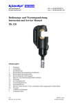
Bedienungsanleitung Instruction Manual Mode d’emploi Handleiding Serialnummer ESG 50 plus JCS HE.4351_H ©5/98 H:\DOKU\BED_KL\HYDR\HE4351_H.doc Anzahl der Seiten: 15 Bedienungsanleitung ESG 50 plus Seite 2 _____________________________________________________________________________________________________________________ Bild/Picture 1 8 3 a 10 b 4 5 6 1 2 9 7 Bild/Picture 2 Bild/Picture 3 10b 10a Bedienungsanleitung ESG 50 plus Seite 3 ______________________________________________________________________________________________________________________ Tabelle 1 (siehe Bild 1 Seite 2) Pos.- Bezeichnung Funktion Nr. 1 BedienungsAuslösung des Schneidvorgangs schalter 2 Rückstelltaste Taste zum Öffnen der Messer im Fehler-, bzw. Notfall 3 Klappriegel Vorrichtung zum Öffnen des Schneidkopfes 4 Schneidkopf Vorrichtung zum Aufnehmen der Messereinsätze 5 Gehäuse Ergonomisch geformtes Kunststoffgehäuse 6 LeuchtdiodenKontrollinstrument zum Feststellen anzeige des Ladezustandes, eines Gerätefehlers und zur Wartungsanzeige. 7 Akku wiederaufladbarer 3Ah NiMH Akku (RA5) 8 Ring Öse zum Sichern des Werkzeuges und/oder zu Montagezwecken. 9 Handschutz Bügel zum Schutz der bedienenden Hand, kein Transportgriff! 10a Klappmesser Feststehendes Gegenmesser 10b Bewegliches bewegliches Schneidemesser Messer Bedienungsanleitung für das elektro-hydraulische Schneidgerät Typ ESG 50 plus, Seriennummer .......................... Inhaltsangabe 1 2 3 4 4.1 4.2 4.3 5 5.1 5.2 5.3 5.4 5.5 6 7 8 Einleitung Aufschriften Gewährleistung Beschreibung des elektro-hydraulischen Schneidgerätes Beschreibung der Komponenten Kurzbeschreibung der wesentlichen Leistungsmerkmale des Gerätes Beschreibung der Leuchtdiodenanzeige Hinweise zum bestimmungsgemäßen Gebrauch Bedienung des Gerätes Erläuterung des Anwendungsbereiches Wartungshinweise Hinweis zur Verwendung des Akkus und des Ladegeräts Aufbewahrung und Transport des Schneidgerätes Verhalten bei Störungen am Schneidgerät Außerbetriebnahme/Entsorgung Technische Daten Symbole Sicherheitstechnische Hinweise Bitte unbedingt beachten, um Personenund Umweltschäden zu vermeiden. 4.2 Kurzbeschreibung der wesentlichen Leistungsmerkmale des Gerätes Anwendungstechnische Hinweise Bitte unbedingt beachten, um Schäden am Gerät zu vermeiden. 1. - Das Gerät besitzt einen manuellen Rücklauf, durch den der Kolben nach Bedarf in die Ausgangslage zurückfahren werden kann. - Das Gerät ist mit einem Nachlaufstop ausgerüstet, der den Vorschub nach Loslassen des Bedienungsschalters (Pos.-Nr. 1) sofort stoppt. - Das Gerät ist mit einer Doppelkolbenpumpe ausgestattet, die durch einen schnellen Vorschub und einen langsamen Arbeitshub gekennzeichnet ist. - Der Schneidkopf ist stufenlos 360° um die Längsachse drehbar. Dieses ermöglicht Montagen auch an sehr schlecht zugänglichen Stellen. - Die ESG 50 plus ist mit einer Mikroprozessor-Steuerung ausgestattet, die Service Intervalle anzeigt, den Ladezustand des Akkus (Pos.-Nr. 7) angibt und eine Fehlerdiagnose durchführt. Einleitung Vor Inbetriebnahme Ihres Schneidgerätes lesen Sie sich die Bedienungsanleitung sorgfältig durch. Benutzen Sie dieses Gerät ausschließlich für den bestimmungsgemäßen Gebrauch. Das Kabelschneidgerät darf nur durch eine elektrotechnisch unterwiesene Person bedient werden. Das Mindestalter beträgt 16 Jahre. Diese Bedienungsanleitung ist während der gesamten Lebensdauer des Gerätes mitzuführen. 4.3 Beschreibung der Leuchtdiodenanzeige Die Leuchtdiode (Pos.-Nr. 6) dient in Verbindung mit der Steuerungs-elektronik zur Information über den Zustand des Akkus (Pos.-Nr. 7) und des Werkzeuges. Im einzelnen leuchtet die Diode in folgenden Fällen: Der Betreiber muß - dem Bediener die Betriebsanleitung zugänglich machen und - sich vergewissern, daß der Bediener sie gelesen und verstanden hat. 2. Signal Aufschriften Auf dem an dem Gehäuse angebrachten Typenschild finden Sie Typbezeichnung, Herkunftsangabe und den Firmennamen. Auf der gegenüberliegenden Seite des Gehäuses befindet sich ein Aufkleber mit einer Kurzdarstellung der schneidbaren Aussen-durchmesser für Kupfer- und Aluminiumkabel und der Schneidkraft. Die Seriennummer befindet sich auf dem Hydraulikzylinder zwischen dem Gehäuse und dem Schneidkopf. Am Schneidkopf befindet sich ein Hinweis auf eine mögliche Verletzungsgefahr bei Schneidvorgängen. 3. 2 Zeitpunkt Bedeutung beim Einsetzen des Durchführung Akkus des Selbsttests Nach dem Akku leer Arbeitsvorgang Nach dem Fehler oder Arbeitsvorgang Wartung fällig Während der Dauer Gerät zu heiß der Übertemperatur Nach dem Wartung fällig Arbeitsvorgang und Akku leer Gewährleistung Die Gewährleistung beträgt bei sachgemäßer Bedienung und unter Einhaltung der vorgeschriebenen Serviceintervalle 6 Monate ab Lieferdatum, sofern keine gesetzlichen Bestimmungen davon abweichende Gewährleistungen fordern. 4. 1 Dauer wenige Sekunden Blinken 20 Sekunden Dauerleuchten 20 Sekunden Blinken (2Hz) 20 Sekunden Blinken (5Hz) 20 Sekunden Leuchten und Blinken 1 Beschreibung des elektro-hydraulischen Schneidgerätes 4.1. Beschreibung der Komponenten Das elektro-hydraulische Schneidgerät mit unserer Typbe-zeichnung ESG 50 plus ist ein handgeführtes Gerät und besteht aus folgenden Komponenten: 2 Anmerkungen: - Blinkt die Leuchtdiode ab einem bestimmten Zeitpunkt immer am Ende eines Arbeitsvorgangs für etwa 20 Sekunden, dann ist eine Wartung fällig. Das Gerät ist baldmöglichst ins Werk einzuschicken. - Beim Auftreten eines Fehlers blinkt die Leuchtdiode gleichfalls am Ende eines Arbeitszykluses. Das Blinken zeigt in diesem Fall das Ansprechen der elektronischen Sicherung an. Eine mögliche Ursache dafür ist der Versuch, einen Zyklus mit einem unzulässig entleerten Akku durchzuführen. Tritt das Blinken auch nach Auswechseln des Akkus weiterhin auf, liegt eine andere Störung vor oder eine Wartung ist fällig. In diesen Fällen ist das Gerät ins Werk einzuschicken. Wird das Gerät zu heiß schaltet sich das Gerät selbständig ab. Nach Absinken der Temperatur ist das Gerät automatisch wieder einsatzbereit. Bedienungsanleitung ESG 50 plus Seite 4 _____________________________________________________________________________________________________________________ 5. Achtung Bei zu intensivem Gebrauch kann es durch Erhitzung zu Schäden am Gerät kommen. Hinweise zum bestimmungsgemäßen Gebrauch Vor Arbeitsbeginn sind alle aktiven, d.h. stromführenden Teile im Arbeitsumfeld des Monteurs freizuschalten. Ist dieses nicht möglich sind entsprechende Schutzvorkehrungen2 für das Arbeiten in der Nähe von unter Spannung stehenden Teilen zu treffen. Achtung Beim Betrieb von Elektromotoren kann es zur Funkenbildung kommen, durch die feuergefährliche oder explosive Stoffe in Brand gesetzt werden können. Es sollte vor Arbeitsbeginn der Ladezustand des Akkus (Pos.-Nr. 7) überprüft worden sein. Ein niedriger Ladezustand kann beispielsweise an der Leuchtdiode (Pos.-Nr. 6) durch ein 20 s’iges Aufleuchten am Ende eines Schnittvorganges erkannt werden. Halten Sie Ihren Arbeitsbereich sauber und aufgeräumt. Verwenden Sie dieses Werkzeug nicht wenn Sie müde sind oder unter Einfluß von Drogen, Alkohol oder Medikamenten stehen. Achtung Das elektrohydraulische Schneidgerät darf nicht bei starkem Regen oder unter Wasser eingesetzt werden. 5.3. Wartungshinweise Das Schneidgerät ist nach jedem Gebrauch zu reinigen und trocken zu lagern. Sowohl Akku als auch Ladegerät müssen vor Feuchtigkeit und vor Fremdkörpern geschützt werden. 5.1. Bedienung des Gerätes Zuerst wird der Klappriegel (Pos.-Nr. 3) ausgerastet (Bild 2 Stellung A) und der Schneidkopf (Pos.-Nr. 4) geöffnet. Anschließend wird das Kabel/der Leiter in den Schneidkopf eingelegt und dieser wieder vollständig geschlossen. Das Gerät ist wartungsfrei, lediglich die Bolzenverbindungen sind leicht einzuölen. Achtung Halten Sie die Schneidmesser scharf und sauber und fetten Sie die Führungen regelmäßig. Achtung Vor Auslösung des Schneidvorganges muß der Schneidkopf sicher verschlossen sein. Im Rahmen des bestimmungsgemäßen Gebrauchs dürfen vom Kunden nur die Schneideinsätze (Pos.-Nr. 10) gewechselt werden. Die Betätigung des Bedienungsschalters (Pos.-Nr. 1) leitet den Schneidvorgang ein, der durch das Zusammenfahren der Schneidmesser (Pos.-Nr. 10) gekennzeichnet wird (Bild 2 Stellung C). Achtung Geräteversiegelung nicht beschädigen! Dabei fährt das auf der Kolbenstange sitzende bewegliche Schneidmesser im Schnellvorschub auf das Kabel zu. Nach Umstellung des Gerätes in den langsameren Arbeitshub wird das Kabel durchtrennt. Ein Schneidvorgang ist abgeschlossen, wenn sich die Messereinsätze (Pos.-Nr. 10) überdecken. Achtung Vor Auswechselung der Schneidmesser unbedingt Akku gegen unbeabsichtigtes Betätigen aus dem Gerät entfernen. Bei Beschädigung der Geräteversiegelung erlischt der Garantieanspruch. Lassen Sie Ihr Gerät nur von qualifiziertem Fachpersonal und nur mit Originalersatzteilen reparieren. Damit wird sichergestellt, dass die Sicherheit des Gerätes erhalten bleibt. 5.4. Hinweis zur Verwendung des Akkus und des Ladegerätes Das Ladegerät ist für 230 V/50-60 Hz ausgelegt. Neue Akkus müssen vor dem erstmaligen Gebrauch geladen werden. Zur Aufladung des Akkus wird der Stecker des Ladegerätes in die Steckdose und der Akku in das Ladegerät eingesteckt. Die Ladezeit beträgt ca. eine Stunde. Der Ladezustand des Akkus3 wird an der Leuchtdiode am Ladegerät abgelesen. Durch Drücken der Rückstelltaste (Pos.-Nr. 2) können im Fehler-, bzw. Notfall die Schneidmesser jederzeit in die Ausgangsposition zurückgefahren werden (Bild 2 Stellung B). Achtung Der Schneidvorgang kann jederzeit durch Loslassen des Betätigungsschalters unterbrochen werden. grün: rot: blinken: 5.2. Erläuterung des Anwendungsbereiches Das Schneidgerät kann Kupfer- und Aluminiumkabel bis zu einem maximalen Außendurchmesser von 50 mm schneiden. Ist der Ladevorgang abgeschlossen wechselt das Ladelicht wieder auf grün, wobei gleichzeitig ein akustisches Signal 5 Sekunden lang ertönt. Achtung Es dürfen nur Kupfer- und Aluminium Kabel geschnitten werden. Es dürfen keine artfremden Akkus weder in der Presse noch im Ladegerät verwendet werden. Achtung Stahlarmierte oder mit einer Stahlseele versehene Kabel und Leitungen dürfen nicht geschnitten werden. Laden Sie Ihren Akku auf, sobald die Geschwindigkeit Ihrer Maschine merklich nachläßt, bzw. die Anzeige am Gerät (siehe Kap. 4.3) auf einen leeren Akku hinweist. Laden Sie nicht vorsichtshalber einen teilentladenen Akku nach. Sollten andere Materialien geschnitten werden müssen, ist eine Rücksprache mit dem Werk zwingend erforderlich. Wenn Sie einen Akku aus einem kürzlich betriebenen Gerät oder einen, der längere Zeit in der Sonne lag, laden, kann das Aufladelicht rot blinken. Warten Sie in diesem Fall eine Weile. Das Aufladen beginnt nach Abkühlung des Akku. Achtung Es dürfen keine unter Spannung stehenden Teile geschnitten werden. Bei der ESG 50 plus handelt es sich um ein handgeführtes Gerät, das nicht eingespannt werden darf. Es darf nicht für den stationären Einsatz verwendet werden. Blinkt das Aufladelicht abwechselnd rot und grün und wird ein Warnsignal 20 sec. lang abgegeben, ist das Aufladen nicht möglich. Die Pole des Ladegerätes oder die des Akkus sind durch Staub verschmutzt oder der Akku ist verbraucht oder beschädigt. Das Gerät ist nicht für den Dauerbetrieb geeignet. Es muß nach ca. 30-40 Schnittvorgängen hintereinander eine Pause von ca. 15 min eingelegt werden um das Gerät abzukühlen. Wollen Sie zwei Akkus nacheinander aufladen, warten Sie 15 min bevor Sie den zweiten Akku laden. 3 2 Siehe DIN EN 50110-1 Akku ist aufgeladen Akku wird gerade geladen. Akku nicht vollständig eingeschoben oder Akku zu heiß, ein akustisches Signal ertönt. Der Ladezustand des Akkus kann auch an der LED des Gerätes durch Leuchten am Ende einer Pressung erkannt werden. Siehe Kap. 4.3. Bedienungsanleitung ESG 50 plus Seite 5 _____________________________________________________________________________________________________________________ Laden Sie den Akku bei einer Raumtemperatur von 10°C bis 40°C. Lassen Sie das Ladegerät nie im Regen oder Schnee liegen. Laden Sie den Akku nicht in Anwesenheit leicht entzündbarer Stoffe oder Gase. Tragen Sie das Ladegerät nie am Netzkabel und ziehen Sie es nicht gewaltsam aus der Steckdose heraus. Stecken Sie keine fremden Gegenstände in die Lüftungsgitter des Ladegerätes. Das Laden der Akkus darf nur in den vom Hersteller vorgeschriebenen Ladegeräten vorgenommen werden. 8. Technische Daten Gewicht des kompl. Gerätes: Schneidkraft: Max. Kabelgröße: Antriebsmotor: Akkuspannung: Akkukapazität: Akku-Ladezeit: Schneidzeit: Schnitte pro Akku: Achtung Stecken Sie den Akku nicht in Ihre Hosentasche oder in Ihre Werkzeugkiste, wenn sich in ihnen leitfähige Teile befinden, wie z.B. Münzen, Schlüssel, Werkzeuge oder andere metallische Teile. Hydrauliköl: Umgebungstemperatur: Schalldruckpegel: Vibrationen: Ziehen Sie den Stecker des Ladegerätes nach dem Laden aus der Steckdose heraus. Nehmen Sie das Ladegerät nicht auseinander. Um die Sicherheit und Zuverlässigkeit des Ladegerätes zu gewährleisten sollten Reparatur, Wartung oder Einstellung durch unser Service-Center durchgeführt werden. 5.5. Aufbewahrung und Transport des Schneidgerätes Um das Schneidgerät vor Beschädigungen zu schützen, muß es nach Gebrauch und nachdem es gesäubert worden ist, in den Transportkoffer Art.-Nr. MKE 50 gelegt werden, der dann anschließend sicher zu verschließen ist. 6. Verhalten bei Störungen am Schneidgerät a.) Regelmäßiges Blinken der Leuchtdiodenanzeige (Pos.-Nr. 6) => Akku (Pos.-Nr. 7) austauschen. Leuchtet die Anzeige weiter, muß das Gerät eingeschickt werden. (siehe auch Kap. 4.3) b.) Das Schneidwerkzeug verliert Öl. => Das Gerät einschicken. Das Gerät nicht öffnen und die Geräteversiegelung nicht entfernen. c.) Schneidwerkzeug erreicht den Enddruck nicht. => Schneidvorgang unterbrechen. Rückstelltaste (Pos.-Nr. 2) gedrückt halten und gleichzeitig Bedienungsschalter ca. 10 sec. Dauer-betätigen. Wird der Fehler dadurch nicht behoben, muß das Gerät ins Werk eingeschickt werden. 7. Außerbetriebnahme/Entsorgung Dieses Gerät fällt in den Geltungsbereich der Europäischen WEEE (2002/96/EG) und RoHS Richtlinien (2002/95/EG), die in Deutschland durch das Elektro- und Elektronikgerätegesetz (ElektroG) umgesetzt wurden. Die WEEE-Richtlinie schreibt die Sammlung und umweltgerechte Verwertung der Elektro- und Elektronik-Altgeräte vor. Informationen dazu finden Sie auf unserer Homepage www.klauke.com unter WEEE & RoHS. Die RoHS Richtlinie untersagt nach dem 01/07/2006 neue Elektround Elektronikgeräte in Verkehr zu bringen, die mehr als 0,1 Gewichts-prozent Blei, Quecksilber, sechswertiges Chrom, polybromiertes Biphenyl (PBB) oder polybromierten Diphenylether (PBDE) oder mehr als 0,01 Gewichtsprozent Cadmium je homogenem Werkstoff enthalten. Akku’s (Pos.-Nr. 5) müssen unter Berücksichtigung der Batterieverordung speziell (getrennt) entsorgt werden. Achtung Das Gerät darf nicht im Restmüll entsorgt werden. Die Entsorgung muß durch den Entsorgungspartner der Fa. Klauke vornehmen werden. Kontaktadresse: [email protected] Maße: ca. 4,7 kg (inklusive Akku) ca. 50 kN ∅ 50 mm (z.B.4 x 150 mm² NYY) Gleichstrom-Permanentfeldmotor 12 V 3 Ah [RA5] ca. 1 h [LG4F], bzw. ¼ h [LG5] 10 s bis 24 s (abhängig vom Kabelquerschnitt) ca. 60 Schnitte (4 x 120 mm² NYY) ca. 65 ml "Shell Tellus T 15" -20°C bis +40°C 70 dB (A) in 1m Abstand < 2,5 m/s² (gewichteter Effektivwert der Beschleunigung) Siehe Bild 2 Anmerkung Diese Bedienungsanleitung kann jederzeit kostenlos unter der Bestell-Nr. HE.4351_H nachbestellt werden. Instruction Manual ESG 50 plus page 6 ______________________________________________________________________________________________________________________ Table 1 (see Picture 1 page 2) Pos.- Description Function No. 1 Trigger switch to start cutting procedure 2 Retract button to open the blades in case of button emergency 3 Latch device to open/close the cutting head 4 Cutting Device for the reception of the blades head 5 Housing ergonomically formed plastic housing for perfect handling with a detachable lid 6 Light diode indicator for tool functions and battery display charge control 7 Battery rechargeable 3Ah NiMH battery (RA5) cartridge 8 Ring Loop to secure the tool and/or for assembly purposes 9 Removable guard to protect the operating hand, not for hand guard transportation 10a Swivel Stationary counter cutting blades for Blade copper and aluminium cables and connectors w/o armour & ACSR 10b moveable Moveable cutting blades for copper and blade aluminium cables and connectors w/o armour & ACSR Instruction Manual for the electric-hydraulic cutting unit Type ESG 50 Plus, Serial-No. ........................... Index 1 2 3 4 4.1 4.2 4.3 5 5.1 5.2 5.3 5.4 5.5 6 7 8 Introduction Labels Warranty Description of the electric-hydraulic cutting unit Description of the components Brief description of the important features of the unit Description of the light diode display Remarks in respect of the determined use Operation of the units Explanation of the application range Service and Maintenance instructions Remarks on the use of the Battery Cartridge and Charger Storage and transport of the cutting unit. Troubleshooting Putting out of operation/waste disposal Technical data Symbols Safety warnings Please do not disregard these instructions in order to avoid human injuries and environmental damages. 4.2. Brief description of the important features of the unit - The hydraulic unit incorporates a manual retraction enabling the user to returns the piston into its starting position if necessary. - The unit is equipped with a special brake which stops the forward motion of the piston/blades when the trigger (Pos.-No. 1) is released. - The unit is equipped with a double piston pump which is characterised by a rapid approach of the blades (Pos.-No. 10) towards the cable and a slow cutting motion. - The cutting head can be smoothly turned by 360° around the longitudinal axis in order to gain better access to tight corners and other difficult working areas. - The ESG 50 Plus is equipped with a microprocessor which indicates service intervals, internal checks and low battery charges. Operational warnings Please do not disregard them to avoid damaging the pump unit. 1. Introduction Before starting to use the tool please read the instruction manual carefully. Use this tool exclusively for its determined use. Mounting and assembly of connecting material with the help of this tool must only be performed by specially trained personnel. The minimum age is 16 years. 4.3. Description of the light diode display This tool is equipped with a special circuit board incorporating several important features to inform the user about the current status of the unit. The diode (Pos.-No. 6) signals in the following cases: This instruction manual has to be carried along during the entire life span of that tool. 2. Signal The operator has - to guaranty the availability of the instruction manual for the user and - to make sure, that the user has read and understood the instruction manual. 1 Labels 2 On the labels fixed on the housing of the tool you’ll find the type specification name of the manufacturer and the company logo. On the opposite side of the housing you’ll find a label with a brief presentation of the scope of manageable cross-sections for copper and aluminium and the cutting force. The serial number is on the hydraulic cylinder between the housing and the cutting head. On the cutting head you’ll find a warning against possible injuries during the cutting process. 3. Warranty If correct operation is guaranteed our warranty is 6 months from the time of delivery unless otherwise specified by local guidelines and law. 4. Description of the electric-hydraulic cutting unit 4.1. Description of the components The electric-hydraulic cutting unit type ESG 50 Plus is a hand held tool and consists of the following components: 1 Duration a few seconds of flashing glowing for 20 seconds flashing for 20 seconds (2Hz) flashing for 20 seconds (5Hz) 20 sec. glowing and flashing intermittently When it occures battery insertion after crimp after crimp During high temperature after crimp What it means self check – O.K. battery discharged return for service unit too hot service required and battery flat Remarks: - Does the diode signal periodically at the end of a working cycle for approx. 20 sec the unit must be returned to an authorised Service Center for Service as soon as possible. - In case of an error the light diode display also signals periodically at the end of a working cycle. The signal indicates in this case the circuit opening by the electronic fuse. A possible reason for that is that a cycle was performed with an incorrectly low battery. If the signal occurs even after changing the battery there must be a different error or a service is due. In these cases the tool must be returned to the manufacturer or an authorised service center. 2 The unit switches off when it gets too hot. It switches on automatically after the unit cooled off. Instruction Manual ESG 50 plus page 7 _______________________________________________________________________________________________________________________ 5. Attention Electric-hydraulic cutting tools should not be operated in pouring rain or under water. Remarks in respect of the determined use Before starting any work on electrical appliances it must be safeguarded that there are no live parts in the immediate assembly area of the user. Is this not possible special precaution1 for working 5.3. Service and maintenance instruction near live parts must be provided. The electric-hydraulic cutting unit is equipped with a sophisticated controller enabling the user to see when the next service is due. (Pls. Prior to operating the unit the charging level of the battery (Pos.read chapter 4.3 for more information) When the next service is due the No. 7) should have been tested2. A low charging level can be unit must to be returned to an authorised service centre. detected by the flashing of the LED (Pos.-No. 6) for 20 sec. at the end of a cutting cycle. For every day service the unit has to be cleaned and dried after each use. The battery cartridge (Pos.-No. 7) and the charging unit have to be Keep your working area clean and tidy. Do not use this tool when protected against humidity and dust. you are tired, on drugs, had alcohol or if you are medicated. Attention Keep the blades sharp and clean and grease the guidance regularly. 5.1. Operation of the unit The cutting head (Pos.-No. 4) has to be opened by unhooking the latch (Pos.-No. 3 & Picture 2 Pos. A). Place the conductor/cable into the open cutting head. Afterwards the cutting head must be completely closed. Within the determined use of the tool only the blades (Pos.-No. 10) are permitted to be changed by the customers. If the seals are damaged the warranty is invalidated. The cutting procedure is initiated by actuating the trigger (Pos.-No. 1 & Picture 2 Pos. C). The cutting process is defined by the closing motion of the blades (Pos.-No. 10). Attention Do not damage the seals of the tool. Have your tool serviced only by qualified service personnel and replace parts only with genuine spare parts. This will make sure that the safety standard of the tool will be preserved. Attention The cutting process can be interrupted at any moment by releasing the trigger. The cutting process is terminated when the cutting blades overlap. After having completed the cut the blades return into the starting position by actuating the retract button (Pos.-No 2, Picture 2 Pos. B) once. After a few seconds a second cutting cycle can be initiated. 5.4 Remarks on the use of the battery cartridge and charging unit. The charging unit is run with a nominal voltage of 230 V and a frequency of 50-60 Hz. New batteries must be charged prior to use. To charge the battery cartridge (Pos.-No. 7) the power plug of the charging unit has to be plugged into the power supply and the battery cartridge has to be pushed into the charging unit. The charging time is one hour. The charging level of the battery cartridge can be checked by a LED3. Attention After having terminated the cutting process and prior to changing the blades remove battery to avoid unintended use. green red flashing 5.2. Explanation of the application range Our electric-hydraulic cutting tool type ESG 50 Plus can cut copper and aluminium conductors or cables up to a maximum diameter of 50 mm. Is the battery plugged in correctly the LED changes from green to red and the charging procedure starts. When the charging procedure is terminated the LED changes again to green. Simultaneously a signal occurs for 5 seconds. Attention Do only cut copper and Aluminium conductors and cables. No other battery cartridges e.g. dry batteries or car batteries etc. are permitted to be used neither in the tool nor in the charging unit. If different conducting materials have to be cut, please contact the manufacturer. As soon as the speed of the machine decreases noticeably the battery must be recharged. Do not recharge a partially discharged battery as a precaution. Attention Do not cut Steel armed cables and conductors or cables with a steel core. If charging a battery which has currently been used or which was laying in the sun for a longer period of time the LED might flash red. In this case wait for a while. The charging procedure starts after the battery cooled down. Attention Do not cut live cables or conductors The ESG 50 Plus is a hand held tool and it is not supposed to be restrained in a vise. It is not allowed to use the tool in a stationary application. Does the LED flash red and green and does an audible tone occur for 20 seconds it is not possible to charge that battery. The poles of the battery or the charging unit are dirty or the battery is low or damaged. If you want to charge two batteries in a row wait for 15 min before you charge the second battery. The tool is not designed for continued cutting operations. After a sequence of approximately 40 completed cuts you have to make a break of 15 min. to give the tool time to cool down. Avoid great fluctuating temperatures under 0°C and above 40°C. Through these fluctuations damages may result for the battery cartridge as well as for the charging unit. The best operation temperature is between 15-25 °C. Attention Too intensive use can cause heat damages for the tool Do not leave or operate the charging unit in rain or snow. Do not charge the battery near lightly inflammable materials or gases. Attention During the operation of electric engines sparks can occur which might ignite highly inflammable or explosive liquids and materials 1 2 See EN 50110-1 See Chapter 5.4 for more information of the battery and charging unit battery cartridge is charged Battery cartridge is empty and is just being charged battery cartridge is not pushed in properly or too hot, a sound signal occurs 3 The charging level of the battery can also be verified by the LED of the tool at the end of a cutting cycle. See chapter 4.3 for further information. Instruction Manual ESG 50 plus page 8 _______________________________________________________________________________________________________________________ Do not use the cord to transport the charging unit or to pull the plug out of a wall socket with force. Do not insert strange parts into the ducts of the charging unit. The charging of the batteries must only be done with charging units supplied by the manufacturer. Attention Do not place the battery in your pocket or in your toolbox if there are any conductive materials in it such as coins, keys, tools or other metallic parts. Pull the plug of the charging unit after charging. Do not disassemble the charging unit or battery. In order to safeguard a safe and proper performance of the charging unit the repair and service of the unit should be made through our Service Centre. 8. Technical Data Weight of the complete tool: Cutting force: Maximum cutting diameter: Driving motor: Battery voltage: Battery capacity Charging time: Cuts per battery: Hydraulic oil: environmental temperature: Sound level: Vibrations: approx. 4,7 kg (incl. battery) approx. 50 kN ∅ 50 mm (e.g. 4 x 150 mm² NYY) direct-current permanent field motor 12 V 3 Ah (RA5) approx. 1 h (LG4F), ¼ h with Quick-charger (LG 5) approx. 10 s to 24 s (depending on the cable size) approx. 60 cuts (4 x 120 mm² NYY) approx. 65 ml "Shell Tellus T 15" -20°C to –40°C 70 dB (A) in 1m distance < 2,5 m/s² Dimensions: See Picture 2 Cutting time: 5.5 Storage and transport of the cutting tool In order to protect the tool against damages it has to be cleaned carefully after each use and be put into the transportation case Part No. MKE 50 which has to be closed safely. 6. Troubleshooting a.) Flashing of the light diode display (Pos.-No. 6) => See chapter 4.3 for more information about the special functions of the tool. b.) The tool loses oil. => Return the tool to the manufacturer. Do not open the tool and damage the seals of the tool. c.) The cutting tool does not reach the final operating pressure. => Stop the cutting process. Press the retract button (Pos.-No. 2) and the operating switch continuously and simultaneously for about 10 sec. Is the malfunction not be eliminated by this attempt the tool has to be returned to the manufacturer. 7. Putting out of operation/waste disposal This unit is subjected to the scope of the European WEEE (2002/96/EG) and RoHS (2002/95/EEC) directives. The WEEE directive regulates the collection and the environmental friendly recycling of electro and electronic units. Information about this can be found in our home page www.Klauke.com under ‘WEEE & RoHS’. The RoHS directive bans new electrical and electronic equipment put on the market which contains more than 0,1 weight percentage lead, mercury, hexavalent chromium, polybrominated biphenyls (PBB) or polybrominated diphenyl ethers (PBDE) and 0,01 weight percentage cadmium per homogeneous material. Battery cartridges (Pos.-No. 7) must be specially disposed of according to the EEC Battery Guideline. Attention Do not dispose of the unit in your residential waste. Klauke has no legal obligation to take care of their WEEE outside Germany unless the product has been shipped and invoiced from inside your country by Klauke. Please contact your distributer to find out more how to get your tool recycled environmental friendly. Additional instruction manuals are available free of charge. The part # is HE.4351_H. Mode d’emploi ESG 50 plus page 9 ______________________________________________________________________________________________________________________ Tableau 1 (voir fig. 1, page 2) N° de Désignation Fonction pos. 1 Commutateur de Déclenchement de l’opération de commande coupe 2 Bouton de Bouton pour ouverture des ciseaux en remise à l'état cas d’erreur, de panne ou d’urgence initial 3 Verrou à crans Dispositif pour ouvrir la tête de coupe rabattable 4 Tête de coupe Dispositif pour recevoir les garnitures des ciseaux 5 Boîtier Boîtier plastique ergonomique 6 Affichage de Instrument de contrôle pour vérifier diode électrol’état de charge, d’une panne luminescente d'appareil, et pour l’annonce de maintenance. 7 Accu Accu rechargeable 3 Ah NiMH (RA5) 8 Anneau Oeillet visant à sécuriser l’appareil et/ou à des fins de montage 9 Protection des Étrier pour protéger la main qui mains commande l’appareil, pas de poignée de transport ! 10a Ciseau articulé Contre-ciseaux fixe 10b Ciseau mobile Ciseau mobile Mode d’emploi pour la cisaille électro-hydraulique type ESG 50 plus, numéro de série .......................... Table des matières 1 2 3 4 4.1 4.2 4.3 5 5.1 5.2 5.3 5.4 5.5 6 7 9 Introduction Inscriptions Garantie Description de la cisaille électro-hydraulique Description des éléments Description rapide des caractéristiques de performance essentielles Description de l’affichage de la diode électroluminescente Indications relatives à l’utilisation conforme Commande de l’appareil Explication du domaine d’application Indications de maintenance Indications sur l’utilisation de l'accu et du chargeur Entreposage et transport de la cisaille Comportement en cas de pannes de la cisaille Mise hors service/mise au rebut Caractéristiques techniques Symboles Indications techniques de sécurité À observer impérativement pour éviter des dommages sur les personnes et l’environnement. 4.2 Description rapide des caractéristiques de performance essentielles Indications techniques d’application À observer impérativement, pour éviter des dommages sur l’appareil. 1. - L’appareil possède un retour manuel qui permet, si nécessaire, de replacer le piston dans la position initiale. - L’appareil est équipé d’un dispositif de freinage qui stoppe immédiatement la poussée après relâchement du commutateur de commande (pos. n° 1). - L’appareil est équipé d’une pompe à double piston qui se caractérise par une avance rapide et une course de travail lente. - La tête de coupe est pivotable en continu à 360° autour de l’axe longitudinal. Ceci permet des montages également à des endroits très difficilement accessibles. - L’ESG 50 plus est équipé d’une commande de microprocesseur qui indique les intervalles de maintenance, affiche l'état de charge de l’accu (pos. n° 7) et effectue un diagnostic d’erreur. Introduction Lisez attentivement le mode d’emploi avant la mise en service de votre cisaille. Utilisez exclusivement cet appareil pour l’utilisation conforme. L’utilisation de la cisaille à câble est strictement réservée à une personne instruite en électrotechnique. L’âge minimum est de 16 ans. Ce mode d’emploi est à conserver avec l’appareil pendant toute sa durée de vie. 4.3 Description de l’affichage de la diode électroluminescente L’exploitant doit - garantir l’accessibilité du mode d’emploi à l’utilisateur - s’assurer que l’utilisateur l’a lu et compris. 2. En relation avec l’électronique de commande, la diode électroluminescente (pos. n° 6) sert à fournir des informations sur l’état de l’accu (pos n° 7) et de l'outil. La diode s’allume dans les cas suivants : Inscriptions Signal Sur la plaque signalétique apposée sur le boîtier vous trouverez la désignation du type, l’indication d’origine et le nom de l’entreprise. Sur le côté opposé du boîtier se trouve un autocollant avec une représentation abrégée des diamètres extérieurs pouvant être coupés pour des câbles de cuivre et d’aluminium ainsi que de la force de coupe. Le numéro de série se trouve sur le cylindre hydraulique entre le boîtier et la tête de coupe. Un avertissement relatif à un risque de blessure éventuel pendant les opérations de coupe est apposé sur la tête de coupe. 3. Garantie La garantie s’élève à 6 mois à partir de la date de livraison dans le cas d’une manipulation adéquate et en observant les intervalles de maintenance prescrits, sous réserve qu’aucune disposition juridique n’exige des garanties divergentes. 4. Description de la cisaille électro-hydraulique Durée Clignotement de quelques secondes Lumière permanente de 20 s Clignotement pendant 20 s (2Hz) Clignotement pendant 20 s (5Hz) 20 s Lumière et clignotement Moment Lors de l’insertion de l’accu Signification Exécution de l’autotest Après l’opération de travail Après l’opération de travail Accu vide Pendant la durée de température supérieure à la normale Après l’opération de travail Panne ou maintenance imminente Appareil trop chaud Maintenance à effectuer et accu vide Remarques: 4.1. Description des éléments La cisaille électro-hydraulique avec notre désignation de type ESG 50 plus est un appareil manié à la main et se compose des éléments suivants : 2 - Si la diode électroluminescente clignote pendant environ 20 s à partir d’une certaine période et toujours à la fin d’une opération, cela signifie qu’une maintenance arrive à échéance. L’appareil est à retourner à l’usine dans les meilleurs délais. - Lors d’une panne, la diode électroluminescente clignote également à la fin d’un cycle de travail. Le clignotement indique dans ce cas la sollicitation de la sécurité électronique. Une cause possible est la tentative d'effectuer un cycle avec un accu vidé de manière inadmissible. Si le clignotement se produit encore après remplacement de l’accu, ceci indique la présence d’une autre panne ou l’arrivée à échéance d’une maintenance. Dans ces cas l’appareil est à retourner à l’usine dans les meilleurs délais. Si l’appareil chauffe de trop, il s’éteint automatiquement. Après baisse de la température l’appareil est à nouveau disponible. Mode d’Emploi ESG 50 plus page 10 _______________________________________________________________________________________________________________________ 5. Attention En cas d’utilisation trop intensive, des dommages peuvent survenir à l’appareil par suite d’échauffement. Indications relatives à l’utilisation conforme Avant le début du travail, toutes les pièces actives, c’est-à-dire conductrices sont à déconnecter dans l'environnement de travail du monteur. Si ceci n’est pas possible il faut prendre les mesures de protection correspondantes2 pour le travail à proximité de pièces sous tension. Attention Le fonctionnement de moteurs électriques peut conduire à la formation d'étincelles qui peuvent mettre le feu à des matières inflammables ou explosives. L’état de charge de l’accu (pos n° 7) doit avoir été vérifié avant le début du travail. Un niveau de charge trop faible peut par exemple être reconnu à la diode électroluminescente (pos. n° 6) qui est allumée en continu pendant 20 s à la fin d’un processus de coupe. Maintenez votre environnement de travail propre et rangé. N’utilisez pas cet outil si vous êtes fatigué ou sous l’influence de drogues, d’alcool ou de médicaments. Attention L'utilisation de la cisaille électro-hydraulique est interdite lors de fortes pluies ou sous de l’eau. 5.3. Indications de maintenance La cisaille doit être nettoyée après chaque utilisation et stockée au sec. Non seulement l’accu mais aussi le chargeur doivent être protégés de l’humidité et de corps étrangers. 5.1. Commande de l’appareil Décliqueter tout d’abord le verrou à crans rabattable (pos. n° 3) (fig. 2, position A), puis ouvrez la tête de coupe (pos. n° 4). Le câble/conducteur est ensuite inséré dans la tête de coupe et celle-ci entièrement fermée. L’appareil est sans entretien, uniquement les articulations d’axes sont à huiler légèrement. Attention Maintenez les ciseaux aiguisés et propres et graissez régulièrement les guidages. Attention Avant déclenchement de l’opération de coupe, la tête de coupe doit être bien fermée. Dans le cadre de l’utilisation conforme, le client est en droit de remplacer uniquement les garnitures de coupe (pos. n° 10). La manipulation du commutateur de commande (pos. n° 1) déclenche l’opération de coupe qui est marqué par la rencontre des ciseaux (pos. n°10) (fig. 2, position C). Attention Ne pas endommager le scellé de l’appareil ! Le ciseau mobile installé sur la tige de piston avance en poussée rapide sur le câble. Après passage de l’appareil dans la course de travail plus lente, le câble est cisaillé. Une opération de coupe est terminée lorsque les garnitures des ciseaux (pos. n° 10) se recouvrent. Attention Avant remplacement des ciseaux veuillez absolument retirer l’accu pour éviter toute manipulation involontaire. Le droit à la garantie expire si le scellé de l’appareil est détérioré. Faites seulement réparer votre appareil par du personnel qualifié et uniquement avec des pièces de rechange d’origine. Ainsi est assuré que la sécurité de l’appareil reste intacte. 5.4. Indications sur l’utilisation de l'accu et du chargeur Le chargeur est conçu pour 230 V/50-60 Hz. De nouveaux accus doivent être chargés avant la première utilisation. Pour le chargement de l’accu, la prise du chargeur est insérée dans la prise de courant et l’accu est placé dans le chargeur. Le temps de charge est d’environ une heure. L’état de charge de l’accu3 est visible au niveau de la diode électroluminescente sur le chargeur. En appuyant sur le bouton de remise à l’état initial (pos. n° 2), les ciseaux peuvent être remis dans la position initiale (fig. 2, position B) en cas de panne ou d’urgence. Attention L’opération de coupe peut être interrompue à tout instant en relâchant le commutateur de commande. Verte : Rouge : Clignotement : 5.2. Explication du domaine d’application La cisaille peut couper des câbles de cuivre et d’aluminium jusqu’à un diamètre extérieur de 50 mm. Une fois l’opération de charge terminée, le voyant de charge passe à nouveau au vert, et un signal sonore retentit simultanément pendant 5 secondes. Attention L’appareil est strictement réservé à la coupe de câbles de cuivre et d’aluminium. Il est strictement interdit d’utiliser un accu d’une autre marque, aussi bien dans la presse que dans le chargeur. Attention Il est interdit de couper des câbles et conduites d’alimentation armés en acier ou avec une âme en acier. Chargez votre accu dès que la vitesse de votre machine diminue sensiblement, ou que l'affichage à l'appareil (voir chap. 4.3) indique que l’accu est vide. Ne rechargez pas par précaution un accu partiellement déchargé. Si d’autres matériaux doivent être coupés, une consultation avec l’usine est impérativement requise. Si vous chargez un accu d’un appareil utilisé récemment ou qui a été longuement exposé au soleil, le voyant de charge rouge peut clignoter. Attendez dans ce cas un moment. La charge commence après refroidissement de l’accu. Attention La coupe de pièces sous tension est strictement interdite. Si le voyant de charge clignote alternativement sur rouge et vert et si un signal d’avertissement retentit pendant 20 s, cela signifie qu’un chargement est impossible. Les pôles du chargeur ou de l’accu sont salis par de la poussière ou l’accu est usé ou endommagé. En ce qui concerne le ESG 50 plus, il s’agit d’un appareil manié à la main qui ne doit pas être placé dans un étau. Il ne doit pas être utilisé pour une application stationnaire. L’appareil n’est pas apte pour un service continu. Une pause d’environ 15 min doit être respectée après environ 30-40 opérations de coupe consécutives afin de laisser refroidir l’appareil. Si vous voulez charger deux accus l’un après l’autre, attendez 15 min avant de charger le deuxième accu. 3 2 Voir DIN EN 50110-1 l’accu est chargé l’accu est en cours de charge l’accu n’est pas entièrement inséré ou trop chaud, un signal acoustique retentit L’état de charge de l’accu peut aussi être reconnu à la DEL de l’appareil qui s’allume à la fin d’une opération de compression. Voir chap. 4.3. Mode d’Emploi ESG 50 plus page 11 _______________________________________________________________________________________________________________________ Chargez l’accu à une température ambiante de 10°C à 40°C. N’exposez jamais le chargeur à la pluie ou à la neige. Ne chargez pas l’accu en présence de matières facilement inflammables ou de gaz. Ne portez jamais le chargeur par le cordon d’alimentation et ne le retirez pas par la force de la prise de courant. Ne mettez pas d’objets étrangers dans les grilles d’aération du chargeur. Le chargement des accus doit être uniquement réalisé dans les chargeurs prescrits par le fabricant. Attention Ne mettez pas l’accu dans votre poche de pantalon ou dans votre caisse à outils si des pièces conductrices s’y trouvent, comme par ex. des pièces de monnaie, clés, outils ou autres pièces métalliques. Retirez la prise du chargeur de la prise de courant après la charge. Ne démontez pas le chargeur. Pour garantir la sécurité et la fiabilité du chargeur, il est recommandé de confier les travaux de réparation, maintenance ou réglage à notre Centre de Service. 8. Caractéristiques techniques Poids complet de l'appareil : Force de coupe : Diamètre de câble maxi : env. 4,7 kg (accu compris) env. 50 kN ∅ 50 mm (par ex. 4 x 150 mm² NYY) Moteur d’entraînement : Moteur à courant continu à champ permanent Tension de l’accu : 12 V Capacité de l’accu : 3 Ah [RA5] Durée de charge de l’accu : env. 1 h [LG4F] ou ¼ h [LG5] Temps de coupe : 10 à 24 s (en fonction de la section du câble) Nombre de coupes par accu : env. 60 coupes (4 x 120 mm² NYY) Huile hydraulique : env. 65 ml « Shell Tellus T 15 » Température ambiante : -20°C à +40°C Niveau de pression acoustique : 70 dB (A) à 1m de distance Vibrations : < 2,5 m/s² (valeur pondérée effective de l’accélération) Dimensions : voir fig. 2 5.5. Entreposage et transport de la cisaille Pour protéger la cisaille de détériorations, celle-ci doit être placée après utilisation et après l’avoir nettoyée, dans la valise de transport réf. MKE 50 qui doit ensuite être fermée avec sûreté. 6. Comportement en cas de pannes de la cisaille a.) Clignotement régulier de l’affichage de la diode électroluminescente (pos. n° 6) => Remplacer l’accu (pos. n° 7) Si l’affichage reste allumé, l’appareil doit être renvoyé à l'usine. (voir aussi chap. 4.3) b.) La cisaille perd de l’huile. => Retourner l’appareil. Ne pas ouvrir l’appareil et ne pas enlever son scellé. c) La cisaille n’atteint pas la pression finale. => Interrompre l’opération de coupe. Appuyer sur le bouton de remise à l’état initial (pos. n° 2) et appuyer simultanément en continu sur le commutateur de commande pendant 10 s environ. Si la panne n’est pas éliminée, retourner l’appareil à l’usine. 7. Mise hors service/mise au rebut Cet appareil entre dans le domaine d’application des directives européennes DEEE (2002/96/CE) (en anglais WEEE) et RDS (2002/95/CE) (en anglais RoHS), qui ont été mises en application en Allemagne par le biais de la loi sur les appareils électriques et électroniques (ElektroG). La directive DEEE fixe des critères spécifiques applicables à la collecte, la manutention et au recyclage écologique des déchets électriques et électroniques. Vous trouverez des informations relatives à ces directives sur notre site www.klauke.com dans la rubrique WEEE & RoHS. La directive RDS interdit depuis le 01/07/2006 de mettre de nouveaux appareils électriques et électroniques en circulation, qui contiennent plus de 0,1 pour cent de poids de plomb, mercure, de chrome hexavalent, de diphenyl-ether polybromé (PBDE) ou plus de 0,01 pour cent de poids de cadmium par matériau homogène. Les accus (pos. n° 5) doivent être éliminés spécialement (séparément) en tenant compte du règlement sur les batteries. Attention L’appareil ne doit pas être éliminé dans les ordures ménagères. La mise au rebut doit être effectuée par le partenaire de recyclage des déchets de l’entreprise Klauke. Adresse de contact : [email protected] Remarque Ce mode d’emploi peut être commandé gratuitement à tout moment avec mention de la réf. HE.4351_H. Service ESG 50 plus Seite/page/pagina 12 ___________________________________________________________________________________________________________________ DEUTSCHLAND Klauke Remscheid Hr. Radtke Auf dem Knapp 46 42855 Remscheid (Germany) ℡ 0049- 2191/907-168 0049- 2191/907-243 [email protected] FRANKREICH KLAUKE FRANCE Mr. Weiten 16, Rue Saint-Louis Z.I. Actisud 57150 Creutzwald (France) ℡ 0033-3-87298470 0033-3-87298479 [email protected] GROßBRITANNIEN Norwich Instrument Services Mr. Norman Cockburn 32 Hellesdon Park Road Drayton High Road Norwich NR6 5DR (UK) ℡ 0044-1603-416900 0044-1603-416902 [email protected] ISRAEL Shay A.U., Ltd. Mr. Shay Ind. Zone Kiriat Arieh Embar Street 23/25 P.O. BOX 10049 49222 Petach Tikva (Israel) ℡ 00972-3-9233601 00972-3-9234601 [email protected] ITALIEN PORTUGAL Palissy Galvani Electricidade S.A. Ms. Anna Pereira Rua Serpa Pinto, 15-A/B 1200-433 Lisboa (Portugal) ℡ 00351-21-3223400 00351-21-3223410 [email protected] SLOWENIEN Isaria d. o.o. Ms. Zorz Proizvdnja in trgovina Cece 2a 1420 Trbovlje (Slovenia) ℡ 00386-356-31800 00386-356-31802 [email protected] SPANIEN/ ANDORRA Gave Electro s.l. Mr. Fernando Carvalho Paratge Coll-Blanc, S/N Aptdo. 12 08430 La Roca del Valles, Barcelona (Spain) ℡ 0034-93-8424887 0034-93-8422755 [email protected] FINNLAND OYElteosähkö AB Mr. Reijo Karlsson Kärsämäentie 23, 20360 Turku (Finland) ℡ 00358-2-4100200 00358-2-4100230 [email protected] WAB Mr. Roberto Aleotti Via F.lli Rosselli 8 40121 Bologna (Italy) ℡ 0039-051-522308 0039-051-522761 [email protected] SÜDARFIKA Eberhardt Martin CC Mr. Roger Martin 55 Evelyn Street Newlands Johannesburg (South Afrika) Post point Delarey 2114 ℡ 0027-11-2880000 0027-11-6732043 [email protected] NIEDERLANDE H.K. Electric B.V. Mr. Ferry Jansen De Steegen 5-7 5320 AB Hedel (Neatherland) ℡ 0031-73-5997599 0031-73-5997590 [email protected] AUSTRALIEN South West Hydraulics (regional) Mr. Hari Goundar 12/38 Lancaster St Ingeleburn NSW 2565 (Australia) ℡ 0061-2-96054199 0061-2-9605 4261 [email protected] ÖSTERREICH Klauke Handelsgesellschaft mbH Mr. Acham Kaiser-Franz-Josef-Str. 9 1230 Wien (Austria) ℡ 0043-1-8893436 0043-1-8893433 [email protected] (regional) Forcorp PTY Ltd. Mr. Bill Westerman 7, Lookout Circle Ellenbrook Western Australia 6069 ℡ 0061-92969090 0061-92969080 [email protected] POLEN/ UKRAINE RB Brexim S.A. Mr. Marynin 7a 05-825 Grodzisk Mazowiecki (Poland) ℡ 0048-22-7344380 0048-22-7344381 [email protected] (regional) The Energy Network PTY LT Mr. Andrew Swindell 2 / 186 Granitie Street Geebung QLD 4034 (Australia) ℡ 0061-7321288999 0061-7321288998 repair@the energynetwork.com.au Service ESG 50 plus Seite/page/pagina 13 ___________________________________________________________________________________________________________________ NEUSEELAND Jonel Hydraulics Ltd. Mr. Gorge Pavletich 91 Lady Ruby Drive East Tamaki Aukland (New Zealand) ℡ 0064-9-2749294 0064-9-2748231 [email protected] TSCHECHISCHE REPUBLIK/SLOVAKEI Klauke z. Nitsch s.r.o. Mr. Jiri Nitsch M. Pujmanove 1220 14000 Praha 4 – Pankrac (Czech Republic) ℡ 00420-261213229 00420-261213218 [email protected] SCHWEDEN AB Lindströms Elverkstad Mr. Anders Bennarsten Propellervägen 7 SE-39241 Kalmar (Sweden) ℡ 0046-480-18877 0046-480-19270 [email protected] NORWEGEN Miltronic AS Mr. Hans Petter Selbo Dolasletta 5, 3408 Tranby N-3421 Lierskogen (Norway) ℡ 0047-32226610 0047-32226656 [email protected] SCHWEIZ Ferratec AG Mr. Bürgisser Großmattstr. 19 CH-8964 Rudolfstetten (Switzerland) ℡ 0041-56-6492121 0041-56-6492141 [email protected] UNGARN Trend Elektro Mr. Istvan Imrik H-1117 Budapest Dombovari ut 5-7 (Ungarn) ℡ 0036-1-464-3118 0036-1-464-3119 [email protected] VOLKSREP. CHINA (regional) Hangzhou Xianhen Equipment Co. Ltd Mr. Wang Laixing Floor 10th Xiangxie Commercial Building, No. 889 Jiangcheng Rd., Hangzhou, 31009 (China) ℡ 86-571-87813666 86-571-56180991 [email protected] TÜRKEI Ünal Kardes Tic A.S. Mr. Servet Diricanli Eski Londra Asfalti No. 6 34630 Besyol-SefaköyIstanbul (Turkey) ℡ 0090-212-6249204 0090-212-5924810 [email protected] (regional) Shanghai Feng Ye Trading Co. Ltd Ms. Zhang Yulian Building D, Lane 1340, No.8 Jin Sha Jiang Rd, Shanghai , 200233 (China) ℡ 86-21-5265 8823 86-21 5265 8829 [email protected] [email protected] RUSSLAND Unit Mark Pro Mr. Igor Goryonov 109147 Moscow Marksistskaya 34, bldg 10 (Russia) ℡ 007-495-7480907 007-495-7483735 [email protected] (regional) Guangzhou Xueqin Electrical Appliance Trading Co. Ltd Ms. Wu Yuwei RM B08 Floor 7th, Huifeng Building, No.75 Xianlie Rd. Guangdong , 510095 (China) ℡ 86-20-37589535* 3068 86-20-87327792 [email protected] (regional) Orionkommash Mr. Y. G. Tyufyakov Erevanskaya Str. 6 620046 Ekaterinburg (Russia) ℡ 007-343-3531153 007-343-3539396 (regional) Beijing Black Eagle Hydraulic Equipment Maintenance Co. Ltd. Mr. Song Junling RM A-2809 The Third Building, No. 1 Shuanguang Rd. West Beijing, 100028 (China) ℡ 86-10-64924396 86-10-58220595 [email protected] RUMÄNIEN Gerkon Electro S.R.L. Mr. Heim Miercurea Ciuc, str.G. Cosbuc nr.45 (Romania) ℡ 0040-266-372108 0040-266-312238 [email protected] Taehyung Hydraulic Tool Mr. Kim 140-5, Gamjeun-Dong, Sasang-Gu Busan 17-060 (Korea) ℡ 0082-51-3171507 0082-51-3171507 [email protected] KROATIEN Konekt d.o.o. Mr. Dubravko Salkovic Cerinina 4 HR-10000 Zagreb (Croatia) ℡ 00385-12361890 00385-12361882 [email protected] KOREA Service ESG 50 plus Seite/page/pagina 14 ___________________________________________________________________________________________________________________ LIBANON Al-Bonian Group Mr. Sleiman Tayouneh,Al-Ghazaleh Building P.O. Box 13 6470 Beirut-Lebanon (Lebanon) ℡ 00961-1-385 708 00961-1-385 714 [email protected] INDIA STI Industries Ms. Supriti Sharma 208, 2nd Floor Dhamji Shamji Udyog Bhavan Veera Desai Road, Andheri (W) Mumbai 400058 (India) ℡ 0091-22-26744096 0091-22-26744044 [email protected] VIETNAM Huu Hong Machinery Co., Ltd Mr. Thach Vu Ngoc Trang 157-159 Xuan Hong Street Ward 12, Tan Binh District Ho Chi Minh City (Vietnam) ℡ 0084-8-8117454 0084-8-8116338 [email protected] TAIWAN Po Charng Co.Ltd Mr. Vincent Chen No. 166, Sung Sin Road Sun Yi Dist, Taipei 110 (Taiwan) ℡ 0084-886227631623 0084-886227667492 [email protected] JAPAN Osaka Hydraulics Mr. Ryoji Furuya 10-32 Egasaki -cho Tsurumi-ku, Yokohama 30-0002 (Japan) ℡ 0081-45-5703830 0081-45-5703831 [email protected] IRLAND Pressure Hydraulic Ltd Mr. Noel Fallon 4086 Unit Greenogue Ind. Est. Rathcoole, Co, Dublin (Ireland) ℡ 00353-1-4588880 00353-1-4588940 [email protected] BELGIEN NBR Nussbaumer & Cie Mr. Jan Verheyen Zinkstraat 10 B-1500 Halle (Belgium) ℡ 0032-23570940 0032-23549679 [email protected] Auf dem Knapp 46 D-42855 Remscheid ____________________________________________________________________________________________________________________ Handgeführtes Elektrowerkzeug Typ ESG 50 plus (D) CE `96 - Konformitätserklärung. Wir erklären in alleiniger Verantwortlichkeit, daß dieses Produkt mit den folgenden Normen oder normativen Dokumenten übereinstimmt: DIN EN 60745-1; EN 12100 T1+2; EN 294; EN 349; EN 60204-1; EN 28662-1; EN 50081-1; EN 50082-2; EN 60529; prEN 982; prEN 1037 gemäß den Bestimmungen der Richtlinien 98/37/EWG, 89/336/EWG (DK) CE `96 - Konformitetserklæring. Vi erklærer under almindeligt ansvardt at dette produkt er i overensstemmelse med folgende normer eller normative dokumenter: EN 60745-1; EN 12100 T1+2; EN 294; EN 349; EN 60204-1; EN 28662-1; EN 50081-1; EN 50082-2; EN 60529; prEN 982; prEN 1037 i henhold til bestemmelseme i direktiverne 98/37/EØF, 89/336/EØF (GB) CE `96 - Declaration of conformity. We declare under our sole responsibility that this product is in conformity with the following standards or normative documents: EN 60745-1; EN 12100 T1+2; EN 294; EN 349; EN 60204-1; EN 28662-1; EN 50081-1; EN 50082-2; EN 60529; prEN 982; prEN 1037 in accordance with the regulations of directives 98/37/EEC, 89/336/EEC (PL) CE `96 - Zgodnosc z dyrektywami CE. Swiadomi odpowiedzialnosci oswiadczamy, ze niniejszy produkt jest zgodny z nastepujacymi normami lub dokumentacja normatywna: EN 60745-1; EN 12100 T1+2; EN 294; EN 349; EN 60204-1; EN 28662-1; EN 50081-1; EN 50082-2; EN 60529; prEN 982; prEN 1037 zgodnie z postanowieniami wytycznych 98/37/EWG, 89/336/EWG (F) CE `96 - Déclaration de conformité. Nous déclarons sous notre seule reponsabilité que ce produit est en conformité avec les normes ou documents normatifs suivants: EN 60745-1; EN 12100 T1+2; EN 294; EN 349; EN 60204-1; EN 28662-1; EN 50081-1; EN 50082-2; EN 60529; prEN 982; prEN 1037 conformément aux réglementations des directives 98/37/CEE, 89/336/CEE (NL) CE `96 - Konformiteitsverklaring. Wij verklaren en wij stellen ons er alleen voor verantwoordelijk dat dit produkt voldoet aan de volgende normen of normatieve documenten: EN 60745-1; EN 12100 T1+2; EN 294; EN 349; EN 60204-1; EN 28662-1; EN 50081-1; EN 50082-2; EN 60529; prEN 982; prEN 1037 overeenkomstig de bepalingen van de richtlijnen 98/37/EEG, 89/336/EEG (I) CE `96 - Dichiarazione di conformità. Dichiariamo sotto la nostra esclusiva responsabilità che questo prodotto è conforme alle seguenti norme e documenti normativi: EN 60745-1; EN 12100 T1+2; EN 294; EN 349; EN 60204-1; EN 28662-1; EN 50081-1; EN 50082-2; EN 60529; prEN 982; prEN 1037 conformemente alle disposizioni delle direttive 98/37/CEE, 89/336/CEE (E) CE `96 - Declaración de conformidad. Declaramos bajo nuestra sola responsabilidad que este producto està en conformidad con las normas o documentos normativos siguientes: EN 60745-1; EN 12100 T1+2; EN 294; EN 349; EN 60204-1; EN 28662-1; EN 50081-1; EN 50082-2; EN 60529; prEN 982; prEN 1037 de acuerdo con las regulaciones de las directivas 98/37/CEE, 89/336/CEE (P) CE `96 - Declaração de conformidade. Declaramos sob nossa exclusiva responsabilidade que este producto cumpre as seguintes normas ou documentos normativos: EN 60745-1; EN 12100 T1+2; EN 294; EN 349; EN 60204-1; EN 28662-1; EN 50081-1; EN 50082-2; EN 60529; prEN 982; prEN 1037 conforme as disposiçoes das directivas 98/37/CEE, 89/336/CEE (S) CE `96 - Konformitetsdeklaration. Vi förklarar pá eget ansvar att denna produkt õverenstämmer med följande normer eller normativa dokument: EN 60745-1; EN 12100 T1+2; EN 294; EN 349; EN 60204-1; EN 28662-1; EN 50081-1; EN 50082-2; EN 60529; prEN 982; prEN 1037 enligt bestãmmelserna i direktiverna 98/37/EG, 89/336/EG (FIN) CE `96 - Todistus slandardinmukaisuudesta. Asiasta vastaavana todistamme täten, että tämä tuote on seuraavien standardien ja standardoimisasiakirjojen vaatimusten mukainen: EN 60745-1; EN 12100 T1+2; EN 294; EN 349; EN 60204-1; EN 28662-1; EN 50081-1; EN 50082-2; EN 60529; prEN 982; prEN 1037 ja vastaa säädoksiä 98/37/EU, 89/336/EU (N) CE `96 - Konformitetserklæring. Vi erklærer på eget ansvarlighet at dette produkt er i overensstemmelse med følgende standarder eller standard-dokumenter: EN 60745-1; EN 12100 T1+2; EN 294; EN 349; EN 60204-1; EN 28662-1; EN 50081-1; EN 50082-2; EN 60529; prEN 982; prEN 1037 i henhold til bestemmelsene i direktive ne 98/37/EØF, 89/336/EØF (GR) CE `96 - ΔΗΛΩΣΗ ΣΥΜΜΟΡΦΩΣΗΣ Με αναληψη συνολικης δηλωνομε. οτι το πορον προιον συμϕωνει με τα παρακατω ποοτυπα και με τα ηροτυηα ηου αναϕερονται στα σχεπκο εγγραϕα EN 60745-1; EN 12100 T1+2; EN 294; EN 349; EN 60204-1; EN 28662-1; EN 50081-1; EN 50082-2; EN 60529; prEN 982; prEN 1037 συμϕωνα με τοχς κονονισμους 98/37/EEC, 89/336/EEC (H) CE `96 – Megfelelőségi nyilatkozat. Kéziműködtetésű elektromos kéziszerszámok: Teljes felelősségel kijelentjük, hogy ezek a termékek a következő szabványokkal és irányelvekkel összhangban vannak: EN 60745-1; EN 12100 T1+2; EN 294; EN 349; EN 60204-1; EN 28662-1; EN 50081-1; EN 50082-2; EN 60529; prEN 982; prEN 1037 és megfelelnek a rendeltetés szerinti 98/37/EEC, 89/336/EEC irányelveknek. (CZ) CE `96 – Prohlášeni o shode. Prohlašujeme na vlastni zodpovednost, ze tyto produkty splnuji následujici normy nebo normativni listiny: EN 60745-1; EN 12100 T1+2; EN 294; EN 349; EN 60204-1; EN 28662-1; EN 50081-1; EN 50082-2; EN 60529; prEN 982; prEN 1037 Ve shode se smernicemi 98/37/EEC, 89/336/EEC (RO) CE `96 - Declaraţie de conformitate. Noi declarăm pe propria răspundere că acest produs este în conformitate cu următoarele norme şi documente normative: EN 60745-1; EN 12100 T1+2; EN 294; EN 349; EN 60204-1; EN 28662-1; EN 50081-1; EN 50082-2; EN 60529; prEN 982; prEN 1037; potrivit dispoziţiilor directivelor 98/37/EEC, 89/336/EEC Remscheid, den 11.02.2008 _____________________________________________ Dipl.-Ing. Joh.-Christoph Schütz, CE-Beauftragter