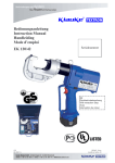
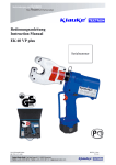
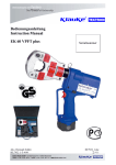
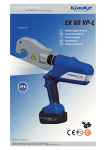
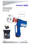
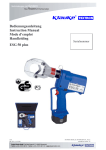
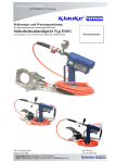
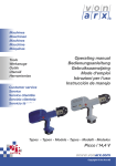
Download EK 22 plus, EK22plusINS
Transcript
Bedienungsanleitung Instruction Manual Handleiding Käyttöohjekirja Mode d’emploi Manual de instrucciones EK 22 plus, EK22plusINS Serialnummer JCS HE.4872_K ©5/98 H:\DOKU\BED_KL\HYDR\HE4872_K.doc Anzahl der Seiten: 28 Bedienungsanleitung EK22plus Seite 2 ____________________________________________________________________________________________________________________ Bild/Picture 1 8 10 4 5 3 6 1 2 10 9 7 Bild/Picture 3 Crimping direction Side b Bild/Picture 4 Crimping direction First crimp Side a First crimp Side b First crimp Crimping direction Side a Bild/Picture 2 Bedienungsanleitung EK22plus Seite 3 ____________________________________________________________________________________________________________________ Bild/Picture 5-7 230V/50Hz Bild/Picture 8 Bild/Picture 9-13 Bedienungsanleitung EK 22 plus Seite 4 ______________________________________________________________________________________________________________________ Tabelle 1 (siehe Bild 1 Seite 2) Pos.- Bezeichnung Funktion Nr. 1 BedienungsAuslösung des Preßvorgangs schalter 2 Rückstelltaste Taste zum Öffnen der Preßeinsätze im Fehler-, bzw. Notfall 3 Zuganker Vorrichtung zum Öffnen des Preßkopfes 4 Druckknöpfe Vorrichtung zum Entriegeln der Preßeinsätze 5 Gehäuse Ergonomisch geformtes Kunststoffgehäuse 6 Leuchtdioden- Kontrollinstrument zum Feststellen des anzeige Ladezustandes, eines Geräte-fehlers und zur Wartungsanzeige. 7 Akku wiederaufladbarer 3Ah NiMH Akku (RA5) 8 Ring Öse zur Sicherung des Gerätes und/oder zu Montagezwecken 9 Handschutz Bügel zum Schutz der bedienenden Hand, kein Transportgriff! 10 Preßeinsätze Halbschalen Werkzeugeinsätze mit unterschiedlichen Preßprofilen Bedienungsanleitung für das elektro-hydraulische Preßgerät Typ EK 22 plus, EK22plusINS Seriennummer ......................... Inhaltsangabe 1 2 3 4 4.1 4.2 4.3 5 5.1 5.2 5.3 5.4 5.5 5.6 6 7 8 Einleitung Aufschriften Gewährleistung Beschreibung des elektro-hydraulischen Preßgerätes Beschreibung der Komponenten Kurzbeschreibung der wesentlichen Leistungsmerkmale des Gerätes Beschreibung der Leuchtdiodenanzeige Hinweise zum bestimmungsgemäßen Gebrauch Bedienung des Gerätes Erläuterung des Anwendungsbereiches Verarbeitungshinweise Wartungshinweise Hinweis zur Verwendung des Akkus und des Ladegeräts Aufbewahrung und Transport des Preßgerätes Verhalten bei Störungen am Preßgerät Außerbetriebnahme/Entsorgung Technische Daten Symbole 4.2 Kurzbeschreibung der wesentlichen Leistungsmerkmale des Gerätes Sicherheitstechnische Hinweise Bitte unbedingt beachten, um Personenund Umweltschäden zu vermeiden. - Das Gerät besitzt einen automatischen Rücklauf, der den Kolben nach Erreichen des max. Betriebsüberdruckes automatisch in die Ausgangslage zurückfährt. - Das Gerät ist mit einem Nachlaufstop ausgerüstet, der den Vorschub nach Loslassen des Bedienungsschalters (Pos.-Nr. 1) sofort stoppt. - Das Gerät ist mit einer Doppelkolbenpumpe ausgestattet, die durch einen schnellen Vorschub und einen langsamen Arbeitshub gekennzeichnet ist. - Der Preßkopf ist stufenlos 360° um die Längsachse drehbar. Dieses ermöglicht Montagen auch an sehr schlecht zugänglichen Stellen. - Die EK 22 plus ist mit einer Mikroprozessor-Steuerung ausgestattet, die den Motor nach vollendetem Preßvorgang abschaltet, Service Intervalle anzeigt, den Ladezustand des Akkus (Pos.-Nr. 7) angibt und eine Fehlerdiagnose durchführt. Anwendungstechnische Hinweise Bitte unbedingt beachten, um Schäden am Gerät zu vermeiden. 1. Einleitung Vor Inbetriebnahme Ihres Preßgerätes lesen Sie sich die Bedienungsanleitung sorgfältig durch. Benutzen Sie dieses Gerät ausschließlich für den bestimmungsgemäßen Gebrauch. 4.3 Beschreibung der Leuchtdiodenanzeige Das Preßgerät darf nur durch eine elektrotechnisch unterwiesene Person bedient werden. Das Mindestalter beträgt 16 Jahre. Die Leuchtdiode (Pos.-Nr. 6) dient in Verbindung mit der Steuerungselektronik zur Information über den Zustand des Akkus (Pos.-Nr. 7) und des Werkzeuges. Im einzelnen leuchtet die Diode in folgenden Fällen: Diese Bedienungsanleitung ist während der gesamten Lebensdauer des Gerätes mitzuführen. Signal Der Betreiber muß - dem Bediener die Betriebsanleitung zugänglich machen und - sich vergewissern, daß der Bediener sie gelesen und verstanden hat. 2. 1 Aufschriften 2 Auf dem an dem Gehäuse angebrachten Typenschild finden Sie Typbezeichnung, Herkunftsangabe und den Firmennamen. Auf der gegenüberliegenden Seite des Gehäuses befindet sich ein Aufkleber mit einer Kurzdarstellung der preßbaren Querschnitte für Kupfer und Aluminium und der Preßkraft. Die Seriennummer befindet sich auf dem Hydraulikzylinder zwischen Gehäuse und Preßkopf. Am Preßkopf befindet sich ein Hinweis auf eine mögliche Quetschgefahr bei Preßvorgängen. 3. Zeitpunkt Bedeutung beim Einsetzen des Durchführung Akkus des Selbsttests Nach dem Akku leer Arbeitsvorgang Nach dem Fehler oder Arbeitsvorgang Wartung fällig Während der Dauer Gerät zu heiß der Übertemperatur Nach dem Wartung fällig Arbeitsvorgang und Akku leer Gewährleistung Die Gewährleistung beträgt bei sachgemäßer Bedienung und unter Einhaltung der vorgeschriebenen Serviceintervalle 6 Monate ab Lieferdatum, sofern keine gesetzlichen Bestimmungen davon abweichende Gewährleistungen fordern. 4. Dauer wenige Sekunden Blinken 20 Sekunden Dauerleuchten 20 Sekunden Blinken (2Hz) 20 Sekunden Blinken (5Hz) 20 Sekunden Leuchten und Blinken 1 Beschreibung des elektro-hydraulischen Preßgerätes 4.1. Beschreibung der Komponenten Das elektro-hydraulische Preßgerät mit unserer Typbezeichnung EK 22 plus ist ein handgeführtes Gerät und besteht aus folgenden Komponenten: 2 Anmerkungen: - Blinkt die Leuchtdiode ab einem bestimmten Zeitpunkt immer am Ende eines Arbeitsvorgangs für etwa 20 Sekunden, dann ist eine Wartung fällig. Das Gerät ist baldmöglichst ins Werk einzuschicken. - Beim Auftreten eines Fehlers blinkt die Leuchtdiode gleichfalls am Ende eines Arbeitszykluses. Das Blinken zeigt in diesem Fall das Ansprechen der elektronischen Sicherung an. Eine mögliche Ursache dafür ist der Versuch, einen Zyklus mit einem unzulässig entleerten Akku durchzuführen. Tritt das Blinken auch nach Auswechseln des Akkus weiterhin auf, liegt eine andere Störung vor oder eine Wartung ist fällig. In diesen Fällen ist das Gerät ins Werk einzuschicken. Wird das Gerät zu heiß schaltet sich das Gerät selbständig ab. Nach Absinken der Temperatur ist das Gerät automatisch wieder einsatzbereit. Bedienungsanleitung EK22plus Seite 5 ____________________________________________________________________________________________________________________ 5. Hinweise zum bestimmungsgemäßen Gebrauch Vor Arbeitsbeginn sind alle aktiven, d.h. stromführenden Teile im Arbeitsumfeld des Monteurs freizuschalten. Ist dieses nicht möglich sind entsprechende Schutzvorkehrungen2 für das Arbeiten in der Nähe von unter Spannung stehenden Teilen zu treffen. Als Sonderausführung wird die EK22plus auch als EK22plusINS mit isolierten Preßkopf angeboten, die besonders für das Arbeiten in der Nähe von unter Spannung stehenden Kabeln konzipiert ist. Es sollte vor Arbeitsbeginn der Ladezustand des Akkus (Pos.-Nr. 7) überprüft worden sein3. Ein niedriger Ladezustand kann beispielsweise an der Leuchtdiode (Pos.-Nr. 6) durch ein 20 s’iges Aufleuchten am Ende einer Pressung erkannt werden. Halten Sie Ihren Arbeitsbereich sauber und aufgeräumt. Verwenden Sie dieses Werkzeug nicht wenn Sie müde sind oder unter Einfluß von Drogen, Alkohol oder Medikamenten stehen. Tabelle 2 Preßbereich mm² 6-300 6-240 10-240 25-185 25/4120/20 5.1. Bedienung des Gerätes Zuerst erfolgt die Auswahl des geeigneten Preßeinsatz (Pos.-Nr. 10). Achtung Preßwerkzeug niemals ohne Preßeinsätze betätigen! Anschließend wird der Zuganker (Pos.-Nr. 3) ausgerastet (Bild 2 Stellung A) und der Preßkopf geöffnet. Die beiden Hälften der Preßeinsätze werden nacheinander seitlich unter Betätigung der Druckknöpfe (Pos. 4) bis zum Einrasten eingeschoben (Bild 2 Stellung E). Nachfolgend wird der Preßkopf wieder vollständig geschlossen wurde. Der Presskopf sollte möglichst vor Beginn des Pressvorganges in die gewünschte Position gedreht werden. Im drucklosen Zustand lässt sich der Presskopf deutlich leichter drehen. Die Betätigung des Bedienungsschalters (Pos.-No. 1) leitet den Preßvorgang ein, der durch das Zusammenfahren der Preßeinsätze gekennzeichnet wird (Bild 2 Stellung C). Dabei befindet sich das auf den Leiter aufgeschobene Verbindungsmaterial bei geschlossenem Preßkopf in dem Preßprofil der stationären Hälfte des Preßeinsatzes4. Ein Preßvorgang ist abgeschlossen, wenn die Preßeinsätze (Pos.Nr. 10) zusammengefahren sind. Der Rücklauf des Kolbens erfolgt automatisch nach Erreichen des max. Betriebsüberdruckes. Anschließend kann ein weiterer Preßvorgang vorgenommen werden oder durch Öffnen des Zugankers (Pos.-Nr. 3) das Verbindungsmaterial aus dem Preßkopf herausgenommen werden. Achtung Vor Auswechselung der Preßeinsätze unbedingt Akku gegen unbeabsichtigtes Betätigen aus dem Gerät entfernen. Durch Drücken der Rückstelltaste (Pos.-Nr. 2) können im Fehler-, bzw. Notfall die Preßeinsätze in die Ausgangsposition zurückgefahren werden (Bild 2 Stellung B). Achtung Der Preßvorgang kann jederzeit durch Loslassen des Betätigungsschalters unterbrochen werden. 5.2. Erläuterung des Anwendungsbereiches Das Preßgerät verfügt über eine große Anzahl verschiedener Preßeinsätze (Pos.-Nr. 10) zum Verpressen von KlaukeVerbindungsmaterial. 10-240 sm 35-300 se 10-70 10-70 10-70 4-50 10-150 2x502x70 10-50 10-70 10-185 2x42x16 (siehe Bild 3 auf Seite 2) Preßeinsätze Kennzeichnung außen Preßprofil RKS und VB CU, QS QS Normalausführung Preß-KS und – CU, QS, KennVB DIN zahl DIN 46235/ 46235 DIN 46267 Aluminium KS AL, QS Kennund VB zahl Al-PreßAl, QS Kennverbinder zahl Aldrey Preßverbinder Al, QS KennDIN 48085 T3 zahl St, QS Kennzahl RunddruckRU; einsatz QS,sm; QS,sm Quetsch-/StiftKS isolierte Quetsch-KS Rohr-RKS für fein-drähtige L. C-Abzweigklemmen RKS und VB isoliert, Stift-KS isoliert Doppel-PreßRKS Nickel-RKS + VB Ovale Preß-VB AEH DIN 46228 Twin AEH Oberfläche des Preßeinsatzes gelb chromatiert Preßbreite gelb chromatiert 5 mm blau verzinkt blau verzinkt 7 mm blau verzinkt brüniert 7 mm gelb chromatiert - 5 mm 7 mm 5 mm CU, QS, DIN 46234 ISQ, QS QS gelb chromatiert - QS - F, QS QS gelb chromatiert gelb chromatiert C, QS - 5 mm IS, QS QS gelb chromatiert gelb chromatiert DP, QS QS Ni, QS - Cu o. Al, QS AE, QS QS AE, 2xQS - - gelb chromatiert blau verzinkt gelb chromatiert gelb chromatiert gelb chromatiert - - 5 mm 5 mm 5 mm - Abkürzungen: RKS=Rohr Kabelschuhe, VB=Verbinder, AEH=Aderendhülsen, QS=Querschnitt, L=Leiter Achtung Es dürfen nur die in Tab. 2 genannten Verbindungsmaterialien verpreßt werden. Sollten andere Verbindungsmaterialien verpreßt werden müssen, ist eine Rücksprache mit dem Werk zwingend erforderlich. Achtung Es dürfen keine unter Spannung stehenden Teile verpreßt werden. Das Werkzeug gilt nicht als isoliert. Bei der EK 22 plus handelt es sich um ein handgeführtes Gerät, das nicht eingespannt werden darf. Es darf nicht für den stationären Einsatz verwendet werden. UnterEinhaltung bestimmter Bedingungen kann das Gerät auch stationär mit unserem Präsentationsständer EKST betrieben werden. Die Bedingungen entnehmen Sie bitte der Bedienungs-anleitung des EKST. Das Gerät ist nicht für den Dauerbetrieb geeignet. Es muß nach ca. 3040 Verpressungen hintereinander eine Pause von ca. 15 min eingelegt werden um das Gerät abzukühlen. 2 Siehe DIN EN 50110-1 siehe Kapitel 5.5 4 Siehe Bild 4 – Montagehinweis für Kabelschuhe und Verbinder 3 Achtung Bei zu intensivem Gebrauch kann es durch Erhitzung zu Schäden am Gerät kommen. Bedienungsanleitung EK22plus Seite 6 ____________________________________________________________________________________________________________________ Blinkt das Aufladelicht abwechselnd rot und grün und wird ein Warnsignal 20 sec. lang abgegeben, ist das Aufladen nicht möglich. Die Pole des Ladegerätes oder die des Akkus sind durch Staub verschmutzt oder der Akku ist verbraucht oder beschädigt. Achtung Beim Betrieb von Elektromotoren kann es zur Funkenbildung kommen, durch die feuergefährliche oder explosive Stoffe in Brand gesetzt werden können. Laden Sie den Akku bei einer Raumtemperatur von 0°C bis 40°C (Bild 8). Lassen Sie das Ladegerät nie im Regen oder Schnee liegen (Bild 10). Laden Sie den Akku nicht in Anwesenheit leicht entzündbarer Stoffe oder Gase (Bild 9). Achtung Das elektrohydraulische Preßgerät darf nicht bei starkem Regen oder unter Wasser eingesetzt werden. Tragen Sie das Ladegerät nie am Netzkabel und ziehen Sie es nicht gewaltsam aus der Steckdose heraus. Stecken Sie keine fremden Gegenstände in die Lüftungsgitter des Ladegerätes (Bild 13). 5.3. Verarbeitungshinweise Bitte beachten Sie unbedingt die im Katalog Kapitel 12 angeführten Montagehinweise5. Das Laden der Akkus darf nur in den vom Hersteller vorgeschriebenen Ladegeräten vorgenommen werden. Achtung Es dürfen auch bei gleicher Kennzahl nur die für das Material vorgesehenen Preßeinsätze verwendet werden. Achtung Stecken Sie den Akku nicht in Ihre Hosentasche oder in Ihre Werkzeugkiste, wenn sich in ihnen leitfähige Teile befinden, wie z.B. Münzen, Schlüssel, Werkzeuge oder andere metallische Teile. 5.4. Wartungshinweise Das Preßgerät ist nach jedem Gebrauch zu reinigen und trocken zu lagern. Sowohl Akku als auch Ladegerät müssen vor Feuchtigkeit und vor Fremdkörpern geschützt werden. Ziehen Sie den Stecker des Ladegerätes nach dem Laden aus der Steckdose heraus (Bild 7). Nehmen Sie das Ladegerät nicht auseinander. Das Gerät ist wartungsfrei, lediglich die Bolzenverbindungen sind leicht einzuölen. Um die Sicherheit und Zuverlässigkeit des Ladegerätes zu gewährleisten sollten Reparatur, Wartung oder Einstellung durch unser ServiceCenter durchgeführt werden. Im Rahmen des bestimmungsgemäßen Gebrauchs dürfen vom Kunden nur die Preßeinsätze (Pos.-Nr. 10) gewechselt werden. 5.6. Aufbewahrung und Transport des Preßgerätes Um das Preßgerät vor Beschädigungen zu schützen, muß es nach Gebrauch und nachdem es gesäubert worden ist, in den Transportkoffer Art.-Nr. MKE 22 gelegt werden, der dann anschließend sicher zu verschließen ist. Achtung Geräteversiegelung nicht beschädigen! Bei Beschädigung der Geräteversiegelung erlischt der Garantieanspruch. 6. Lassen Sie Ihr Gerät nur von qualifiziertem Fachpersonal und nur mit Originalersatzteilen reparieren. Damit wird sichergestellt, dass die Sicherheit des Gerätes erhalten bleibt. a.) Regelmäßiges Blinken der Leuchtdiodenanzeige (Pos.-Nr. 6) => Akku (Pos.-Nr. 7) austauschen. Leuchtet die Anzeige weiter, muß das Gerät eingeschickt werden. (siehe auch Kap. 4.3) b.) Das Preßwerkzeug verliert Öl. => Das Gerät einschicken. Das Gerät nicht öffnen und die Geräteversiegelung nicht entfernen. 5.5. Hinweis zur Verwendung des Akkus und des Ladegerätes Das Ladegerät ist für 230 V/50-60 Hz ausgelegt. Neue Akkus müssen vor dem erstmaligen Gebrauch geladen werden. Zur Aufladung des Akkus wird der Stecker des Ladegerätes in die Steckdose und der Akku in das Ladegerät eingesteckt (Bild 5). Die Ladezeit beträgt ca. eine Stunde (Bild 6). Der Ladezustand des Akkus6 wird an der Leuchtdiode am Ladegerät abgelesen. grün: rot: blinken: Akku ist aufgeladen Akku wird gerade geladen. Akku nicht vollständig eingeschoben oder Akku zu heiß, ein akustisches Signal ertönt. Ist der Ladevorgang abgeschlossen wechselt das Ladelicht wieder auf grün, wobei gleichzeitig ein akustisches Signal 5 Sekunden lang ertönt. Es dürfen keine artfremden Akkus weder in der Presse noch im Ladegerät verwendet werden. Laden Sie Ihren Akku auf, sobald die Geschwindigkeit Ihrer Maschine merklich nachläßt, bzw. die Anzeige am Gerät (siehe Kap. 4.3) auf einen leeren Akku hinweist. Laden Sie nicht vorsichtshalber einen teilentladenen Akku nach. (Bild 11) Wenn Sie einen Akku aus einem kürzlich betriebenen Gerät oder einen, der längere Zeit in der Sonne lag, laden, kann das Aufladelicht rot blinken. Warten Sie in diesem Fall eine Weile. Das Aufladen beginnt nach Abkühlung des Akku. Wollen Sie zwei Akkus nacheinander aufladen, warten Sie 15 min bevor Sie den zweiten Akku laden. 5 Siehe auch Bild 4 auf Seite 2 dieser Bedienunganleitung Der Ladezustand des Akkus kann auch an der LED des Gerätes durch Leuchten am Ende einer Pressung erkannt werden. Siehe Kap. 4.3. 6 Verhalten bei Störungen am Preßgerät c.) Preßwerkzeug erreicht den Enddruck nicht. => Preßvorgang unterbrechen. Rückstelltaste (Pos.-Nr. 2) gedrückt halten und gleichzeitig Bedienungsschalter ca. 10 sec. Dauerbetätigen. Wird der Fehler dadurch nicht behoben, muß das Gerät ins Werk eingeschickt werden. 7. Außerbetriebnahme/Entsorgung Dieses Gerät fällt in den Geltungsbereich der Europäischen WEEE (2002/96/EG) und RoHS Richtlinien (2002/95/EG), die in Deutschland durch das Elektro- und Elektronikgerätegesetz (ElektroG) umgesetzt wurden. Die WEEE-Richtlinie schreibt die Sammlung und umweltgerechte Verwertung der Elektro- und Elektronik-Altgeräte vor. Informationen dazu finden Sie auf unserer Homepage www.klauke.com unter WEEE & RoHS. Die RoHS Richtlinie untersagt nach dem 01/07/2006 neue Elektro- und Elektronikgeräte in Verkehr zu bringen, die mehr als 0,1 Gewichtsprozent Blei, Quecksilber, sechswertiges Chrom, polybromiertes Biphenyl (PBB) oder polybromierten Diphenylether (PBDE) oder mehr als 0,01 Gewichtsprozent Cadmium je homogenem Werkstoff enthalten. Akku’s (Pos.-Nr. 5) müssen unter Berücksichtigung der Batterieverordung speziell (getrennt) entsorgt werden. Achtung Das Gerät darf nicht im Restmüll entsorgt werden. Die Entsorgung muß durch den Entsorgungspartner der Fa. Klauke vornehmen werden. Kontaktadresse: [email protected] Bedienungsanleitung EK22plus Seite 7 ____________________________________________________________________________________________________________________ 8. Technische Daten Gewicht des kompl. Gerätes: Preßkraft: Antriebsmotor: Akkuspannung: Akkukapazität: Akku-Ladezeit: Preßzeit: Pressungen pro Akku: Hydrauliköl: Umgebungstemperatur: Schalldruckpegel: Vibrationen: Maße: Instruction Manual ca. 4,15 kg (inklusive Akku) ca. 60 kN Gleichstrom-Permanentfeldmotor 12 V 3 Ah (RA5) ca. 1 h [LG4F], bzw. ¼ h [LG5] 3 s bis 6 s (abhängig vom Verbinderquerschnitt) ca. 170 Pressungen (Cu 150 mm² DIN 46235) ca. 65 ml "Shell Tellus T 15" -20°C bis +40°C 70 dB (A) in 1m Abstand < 2,5 m/s² (gewichteter Effektivwert der Beschleunigung) Siehe Bild 2 Anmerkung Diese Bedienungsanleitung kann jederzeit kostenlos unter der Bestell-Nr. HE.4872_K nachbestellt werden. for the electric-hydraulic crimping unit Type EK 22 Plus, Serial-No. ......................... Index 1 2 3 4 4.1 4.2 4.3 5 5.1 5.2 5.3 5.4 5.5 5.6 6 7 8 Introduction Labels Warranty Description of the electric-hydraulic crimping unit Description of the components Brief description of the important features of the unit Description of the light diode display Remarks in respect of the determined use Operation of the units Explanation of the application range Mounting instructions Service and Maintenance instructions Remarks on the use of the Battery Cartridge and Charger Storage and transport of the crimping unit. Troubleshooting Putting out of operation/waste disposal Technical data Symbols Safety warnings Please do not disregard these instructions in order to avoid human injuries and environmental damages. Operational warnings Please do not disregard them to avoid damaging the pump unit. 1. Introduction Before starting to use the tool please read the instruction manual carefully. Use this tool exclusively for its determined use. Mounting and assembly of connecting material with the help of this tool must only be performed by specially trained personnel. The minimum age is 16 years. This instruction manual has to be carried along during the entire life span of that tool. The operator has - to guaranty the availability of the instruction manual for the user and - to make sure, that the user has read and understood the instruction manual. 2. Labels On the labels fixed on the housing of the tool you’ll find the type specification name of the manufacturer and the company logo. On the opposite side of the housing you’ll find a label with a brief presentation of the scope of manageable cross-sections for copper and aluminium and the crimping force. The serial number is on the hydraulic cylinder between the housing and the crimping head. On the crimping head you’ll find a warning against possible injuries during the crimping process. 3. Warranty If correct operation is guaranteed our warranty is 6 months from the time of delivery unless otherwise specified by local guidelines and law. 4. Description of the electric-hydraulic crimping unit 4.1. Description of the components The electric-hydraulic crimping unit type EK 22 Plus is a hand held tool and consists of the following components: Instruction Manual EK 22 plus page 8 ______________________________________________________________________________________________________________________ Table 1 (see Picture 1 page 2) Pos.- Description Function No. 1 Trigger switch to start crimping procedure 2 Retract button to open the dies in case of button emergency 3 Latch device to open/close the crimping head 4 Retaining button to unlock/remove the dies clips 5 Housing ergonomically formed plastic housing for perfect handling with a detachable lid 6 Light diode indicator for tool functions and battery display charge control 7 Battery rechargeable 3 Ah NiMH battery cartridge (RA5) 8 Ring Loop to secure the tool and/or for assembly purposes 9 Removable guard to protect the operating hand, hand guard not for transportation 10 Dies interchangeable crimping dies 5. Before starting any work on electrical appliances it must be safeguarded that there are no live parts in the immediate assembly area of the user. Is this not possible special precaution measures1 for working near live parts must be provided. The EK22plus is also available as an EK22plusINS with an insulated head which is specially designed for working near live lines. Prior to operating the unit the charging level of the battery (Pos.-No. 7) should have been tested2. A low charging level can be detected by the flashing of the LED (Pos.-No. 6) for 20 s at the end of a crimping cycle. Keep your working area clean and tidy. Do not use this tool when you are tired, on drugs, had alcohol or if you are medicated. 5.1. Operation of the unit Now you have to select the right dies (Pos.-No. 10) for the intended application. Attention Don’t operate the tool without dies. The crimping head has to be opened by unhooking the latch (Pos.-No. 3 & Picture 2 Pos. A). Afterwards the retaining clips (Pos.-# 4) have to be actuated (Picture 2 Pos. E) while the dies will be inserted sideways into the open crimping head. Afterwards the crimping head must be closed completely. 4.2. Brief description of the important features of the unit - The hydraulic unit incorporates an automatic retraction which returns the piston into its starting position when the maximum operating pressure is reached. - The unit is equipped with a special brake which stops the forward motion of the piston/dies when the trigger (Pos.-No. 1) is released. - The unit is equipped with a double piston pump which is characterised by a rapid approach of the dies (Pos.-No. 10) towards the connector and a slow crimping motion. - The crimping head can be smoothly turned by 360° around the longitudinal axis in order to gain better access to tight corners and other difficult working areas. - The EK 22 Plus is equipped with a microprocessor which indicates service intervals, internal checks and low battery charges. It also shuts off the motor automatically after the crimp is completed. The crimping head should be turned into the desired position before starting the crimping cycle. It is significantly easier to turn the crimping head in a pressure free state. The crimping procedure is initiated by actuating the trigger (Pos.-No. 1 & Picture 2 Pos. C). The crimping process is defined by the closing motion of the dies. During that process the connecting material is positioned in the stationary half of the die whereas the moving part of the die is approaching the compression point3. The crimping process is terminated when the crimping force is reached. After having completed the crimp the dies return into the starting position automatically. Afterwards a second crimping cycle can be initiated or the it can be finished by opening the latch (Pos.-No. 3 & Picture 2 Pos. A). 4.3. Description of the light diode display This tool is equipped with a special circuit board incorporating several important features to inform the user about the current status of the unit. The diode (Pos.-No. 6) signals in the following cases: Signal Duration 1 a few seconds of flashing glowing for 20 seconds flashing for 20 seconds (2Hz) flashing for 20 seconds (5Hz) 20 sec. glowing and flashing intermittently 2 When it occures battery insertion after crimp What it means after crimp return for service During high temperature after crimp unit too hot Remarks in respect of the determined use Attention After having terminated the crimping process and prior to changing the dies remove battery to avoid unintended starts. In case of error or emergency the dies can be returned into the starting position by actuating the retract button (Pos.-No. 2 & Picture 2 Pos. B). self check – O.K. Attention The crimping process can be interrupted at any moment by releasing the trigger. battery discharged 5.2. Explanation of the application range The EK 22 Plus has a large number of various dies (Pos.-No. 10) available to crimp Klauke connecting material. service required and battery flat 1 Remarks: - Does the diode signal periodically at the end of a working cycle for approx. 20 sec the unit must be returned to an authorised Service Center for Service as soon as possible. - In case of an error the light diode display also signals periodically at the end of a working cycle. The signal indicates in this case the circuit opening by the electronic fuse. A possible reason for that is that a cycle was performed with an incorrectly low battery. If the signal occurs even after changing the battery there must be a different error or a service is due. In these cases the tool must be returned to the manufacturer or an authorised service center. 2 The unit switches off when it gets too hot. It switches on automatically after the unit cooled off. 1 See EN 50110-1 See Chapter 5.5 for more information of the battery and charging unit 3 See picture 4 page 2 2 Instruction Manual EK22plus page 9 ______________________________________________________________________________________________________________________ Table 2 (see Picture 3, page 2) Crimping Crimping Marking dies range mm² outside 6-300 TCL and C. CU, Standard „QS“ Version 6-240 TCL and C. CU, DIN 46235/ „QS“, DIN 46267 DIN 46235 10-240 Aluminium AL, CL and C. „QS“ 25-185 Aluminium Al, C. Aldrey „QS“ 25/4Full tension Al, 120/20 C. „QS“ DIN 48085 ST, T3 „QS“ 10-240 PreRU; sm rounding QS, sm; 35-300 dies QS, sm se 10-70 Terminals CU, DIN 46234 „QS“, DIN 46230 DIN 46234 10-70 insulated ISQ, QS terminals 10-70 tub. CL for F, QS fine-str. conductors 4-50 C-clamps C, QS 10-150 2x502x70 10-50 10-70 10-185 Preinsulated tub. CL and connectors double compression CL Ni-CL and connectors Oval compression joints WF DIN 46228 Twin WF IS, QS Surface of the dies chrome plated crimping width chrome plated 5 mm blue zinc blue zinc blue zinc black 7 mm - chrome plated - „QS“ chrome plated - „QS“ chrome plated, chrome plated - chrome plated chrome plated 5 mm Profile „QS“ code # code # code # code # code # „QS“ „QS“ Attention During the operation of electric engines sparks can occur which might ignite highly inflammable or explosive liquids and materials 5 mm Attention Electric-hydraulic crimping tools should not be operated in pouring rain or under water. 5.3. Mounting instructions Please read the assembly instructions in Chapter 12 of our general catalogue. 7 mm Attention Even if the code number is identical only those dies should be used whichare suitable for the material. 7 mm Please use the following assembly instructions for cable lugs and connectors: 1. Strip the conductor according to insertion depth (+10% due to the change of length of the crimped sleeve) 2. The Conductor ends must be cleaned with a cloth or brush before the assembly. 3. Insert the conductor fully into the cable lug or connector 4. Pay attention to the crimping directions and use the appropriate dies. The crimping directions3 for cable lugs and connectors is indicated in the illustration below. 5. After crimping, wipe away excess compound forced out of Al-cable lugs and connectors. 5 mm - 5.4 Service and maintenance instruction - The electric-hydraulic crimping unit is equipped with a controller enabling the user to see when the next service is due. (Pls. read chapter 4.3 for more information) When the next service is due the unit must to be returned to an authorised service center. DP, QS „QS“ chrome plated 5 mm For every day service the unit has to be cleaned and dried after each use. The battery cartridge (Pos.-No. 7) and the charging unit have to be protected against humidity and dust. NI, QS - 5 mm Within the determined use of the tool only the dies (Pos.-No. 10) are permitted to be changed by the customers. CU or AL, QS code # blue zinc chrome plated AE, QS - chrome plated 2x4AE, chrome 2x16 2xQS plated Abbreviations: TCL-Tubular cable lugs, C-Connectors, WF-Wire Ferrules, QS-Cross-section 5 mm Attention Do not damage the seals of the tool. - If the seals are damaged the warranty is invalidated. - Have your tool serviced only by qualified service personnel and replace parts only with genuine spare parts. This will make sure that the safety standard of the tool will be preserved. 5.5 Remarks on the use of the battery cartridge and charging unit. Attention Do only crimp those connecting materials mentioned in Tab. 2 The charging unit is run with a nominal voltage of 230 V and a frequency of 50-60 Hz. New batteries must be charged prior to use. To charge the battery cartridge (Pos.-No. 7) the power plug of the charging unit has to be plugged into the power supply and the battery cartridge has to be pushed into the charging unit (Picture 5). The charging time is one hour (Picture 6). The charging level of the battery cartridge can be checked by a LED4. If different conducting materials have to be crimped, please contact the manufacturer. Attention Do not crimp on live cables or conductors! This is not considered an insulated tool green red flashing The EK 22 Plus is a hand held tool and it is not supposed to be restrained in a vise. It is not allowed to use the tool in a stationary application. Complying certain conditions the unit can be operated stationary with our presentation support EKST. The conditions can be taken from the instruction manual of the EKST. Is the battery plugged in correctly the LED changes from green to red and the charging procedure starts. When the charging procedure is terminated the LED changes again to green. Simultaneously a signal occurs for 5 seconds. The tool is not designed for continued crimping operations. After a sequence of approximately 30-40 completed crimps you have to make a break of 15 min. to give the tool time to cool down. Attention Too intensive use can cause heat damages for the tool battery cartridge is charged Battery cartridge is empty and is just being charged battery cartridge is not pushed in properly or too hot, a sound signal occurs No other battery cartridges e.g. dry batteries or car batteries etc. are permitted to be used neither in the tool nor in the charging unit. 3 See Picture 4 on Page 2 The charging level of the battery can also be verified by the LED of the tool at the end of a crimping cycle. See chapter 4.3 for further information. 4 Instruction Manual EK22plus page 10 ______________________________________________________________________________________________________________________ As soon as the speed of the machine decreases noticeably the battery must be recharged. Do not recharge a partially discharged battery as a precaution (Picture 11). Attention Do not dispose of the unit in your residential waste. Klauke has no legal obligation to take care of their WEEE outside Germany unless the product has been shipped and invoiced from inside your country by Klauke. Please contact your distributer to find out more how to get your tool recycled environmental friendly. If charging a battery which has currently been used or which was laying in the sun for a longer period of time the LED might flash red. In this case wait for a while. The charging procedure starts after the battery cooled down. 8. Does the LED flash red and green and does an audible tone occur for 20 seconds it is not possible to charge that battery. The poles of the battery or the charging unit are dirty or the battery is low or damaged. If you want to charge two batteries in a row wait for 15 min before you charge the second battery. Avoid great fluctuating temperatures under 0°C and above 40°C (Picture 8). Through these fluctuations damages may result for the battery cartridge as well as for the charging unit. The best operation temperature is between 15-25 °C. Do not leave or operate the charging unit in rain or snow (Picture 10). Do not charge the battery near lightly inflammable materials or gases (Picture 9). Do not use the cord to transport the charging unit or to pull the plug out of a wall socket with force. Do not insert strange parts into the ducts of the charging unit (Picture 13). The charging of the batteries must only be done with charging units supplied by the manufacturer. Attention Do not place the battery in your pocket or in your toolbox if there are any conductive materials in it such as coins, keys, tools or other metallic parts. Pull the plug of the charging unit after charging (Picture 7). Do not disassemble the charging unit or battery. In order to safeguard a safe and proper performance of the charging unit the repair and service of the unit should be made through our Service Center. 5.6 Storage and transport of the crimping tool In order to protect the tool against damages it has to be cleaned carefully after each use and be put into the transportation case Part No. MKE 22 which has to be closed safely. 6. Troubleshooting a.) Flashing of the light diode display (Pos.-No. 6) => See chapter 4.3 for more information about the special functions of the tool. b.) The tool loses oil. => Return the tool to the manufacturer. Do not open the tool and damage the seals of the tool. c.) The crimping tool does not reach the final operating pressure. => Stop the crimping process. Press the retract button (Pos.-No. 2) and the operating switch continuously and simultaneously for about 10 sec. Is the malfunction not be eliminated by this attempt the tool has to be returned to the manufacturer. 7. Putting out of operation/waste disposal This unit is subjected to the scope of the European WEEE (2002/96/EG) and RoHS (2002/95/EEC) directives. The WEEE directive regulates the collection and the environmental friendly recycling of electro and electronic units. Information about this can be found in our home page www.Klauke.com under ‘WEEE & RoHS’. The RoHS directive bans new electrical and electronic equipment put on the market which contains more than 0,1 weight percentage lead, mercury, hexavalent chromium, polybrominated biphenyls (PBB) or polybrominated diphenyl ethers (PBDE) and 0,01 weight percentage cadmium per homogeneous material. Battery cartridges (Pos.-No. 7) must be specially disposed of according to the EEC Battery Guideline. Technical Data Weight of the complete tool: Crimping force: Driving motor: Battery voltage: Battery capacity Charging time: Hydraulic oil: Environmental temperature: Sound level: Vibrations: approx. 4,15 kg (incl. battery) approx. 60 kN direct-current permanent field motor 12 V 3 Ah (RA5) approx. 1 h (LG 4), ¼ h with Quick charger (LG 5) approx. 3 s to 6 s (depending on the connector size) approx. 170 crimps (Cu 150 mm² DIN 46235) approx. 65 ml "Shell Tellus T 15" -20°C to –40°C 70 dB (A) in 1m distance < 2,5 m/s² Dimensions: See Picture 2 Crimping time: Crimp per battery: Additional instruction manuals are available free of charge. The part # is HE.4872_K. Handleiding EK 22 plus pagina 11 ______________________________________________________________________________________________________________________ Handleiding voor de accu persmachine type EK 22 plus, serienummer ......................... Inhoud Tabel 1 (zie afbeelding 1) Pos. Omschrijving 1 Bedieningsschakelaar 2 Teruglooptoets 1. Inleiding 2. Labels 3. Garantie 4. Beschrijving van het elektrisch - hydraulisch persapparaat 4.1. Beschrijving van de componenten 4.2. Korte beschrijving van de belangrijkste mogelijkheden van het apparaat 4.3. Beschrijving van de lichtdiode - indicatie 5. Aanwijzingen voor het beoogd gebruik 5.1. Bediening van het apparaat 5.2. Verklaring van het toepassingsgebied 5.3. Verwerkingsaanwijzingen 5.4. Onderhoudsaanwijzingen 5.5. Aanwijzing bij het gebruik van de accu en het laadapparaat 5.6. Opbergen en transport van het persapparaat 6. Wat te doen bij storingen van het persapparaat 7. Buiten werking stellen / Weggooien 8. Technische gegevens Symbolen Veiligheidstechnische aanwijzingen Absoluut opvolgen om schade aan personen en milieu te voorkomen. I 1. Toepassingstechnische aanwijzingen Absoluut opvolgen om schade aan personen en milieu te voorkomen. Inleiding Lees voordat u uw persapparaat in gebruik neemt de handleiding zorgvuldig door. Gebruik dit apparaat uitsluitend voor het doel waarvoor het gemaakt is en volg daarbij de algemene veiligheidsvoorschriften en de voorschriften ter voorkoming van ongevallen op. Gebruik het apparaat uitsluitend voor het beoogde doel. Deze handleiding moet tijdens de totale levensduur van het apparaat zorgvuldig bewaard worden. De gebruiker moet - zorgen dat de handleiding beschikbaar is voor de operator en - er zich van overtuigen dat de operator deze gelezen en begrepen heeft 2. 3. Garantie De garantie bij deskundig gebruik en regelmatig onderhoud van het apparaat bedraagt 12 maanden vanaf de leverdatum. 4. Beschrijving van het elektrisch - hydraulisch persapparaat 4.1. Beschrijving van de componenten Het elektrisch - hydraulisch persapparaat met onze typeaanduiding EK 22 plus is een handbediend apparaat en bestaat uit de volgende componenten: Trekstaaf 4 Drukknoppen 5 Behuizing 6 Lichtdiode - indicatie 7 8 9 Accu Handbescherming 10 Matrijzen 11 Accu borgveer Toets voor het teruglopen van de zuigerstang bij storingen en / of noodgevallen. Inrichting om de persbekhouder te openen Inrichting om de matrijzen te ontgrendelen Ergonomisch uitgevoerde kunststof behuizing met afneembare deksel Controle instrument voor het vaststellen van de laadstand en Verdere apparaat functies. Oplaadbare 3 Ah NiMH accu (RA5) Beugel ter bescherming van de bedienende hand Halfschaalvormige, onderling uitwisselbare matrijzen Veer om de accu vast te zetten 4.2. Korte beschrijving van de belangrijkste mogelijkheden van het apparaat - Het apparaat bezit een automatische terugloop die de aandrijfrollen na het bereiken van de max. bedrijfsdruk automatisch naar de uitgangspositie terugbrengt. - Het apparaat heeft een naloopstop die de voortstuwende beweging direct stopt nadat de bedieningsschakelaar is losgelaten (pos.nr. 1). - Het apparaat heeft een dubbele zuigerpomp die door een snelle voortstuwende beweging en een langzame werkslag gekenmerkt wordt. - De persbekhouder (pos. 4) is traploos 360° om de lengteas draaibaar. Hierdoor is ook montage op zeer slecht toegankelijke plaatsen mogelijk. - De EK 22 Plus heeft een microprocessor besturing die de motor na het persen uitschakelt, service - intervallen aangeeft, de laadstand van de accu (pos.nr. 7) aangeeft en een foutdiagnose uitvoert. 4.3. Beschrijving van de lichtdiode-indicatie De lichtdiode (pos.-nr. 6) dient in combinatie met de besturingselektronica voor het verstrekken van informatie over de toestand van de accu (pos.-nr. 7) en van het werktuig. Concreet brandt de diode in de volgende gevallen: Signaal Labels Op het op de behuizing bevestigde typeplaatje vindt u de typeaanduiding, informatie over de fabrikant en de firmanaam. Op de tegenoverliggende zijde van de behuizing bevindt zich een sticker met de technische gegevens en het serienummer. Op de persbekhouder bevindt zich een waarschuwing tegen mogelijk pletgevaar bij het persen. 3 Functie Starten van het persen 1 2 Duur enkele seconden knipperen 20 seconden continulicht 20 seconden knipperen (2Hz) 20 seconden knipperen (5Hz) 20 seconden branden en knipperen Tijdstip bij het inleggen van de accu na het werken Betekenis bezig met de zelftest accu leeg na het werken fout of onderhoud noodzakelijk apparaat te heet tijdens de duur van de overtemperatuur na het werken onderhoud noodzakelijk en accu leeg 1 Opmerkingen: - Als de lichtdiode vanaf een bepaald moment altijd op het einde van een werkcyclus gedurende ongeveer 20 seconden knippert, is een onderhoud noodzakelijk. Het apparaat moet zo snel mogelijk naar de fabriek worden gestuurd. - De lichtdiode knippert eveneens op het einde van een werkcyclus wanneer een fout is opgetreden. Het knipperen geeft in dit geval aan dat de elektronische zekering is aangesproken. Een mogelijke oorzaak hiervoor is de poging een cyclus uit te voeren met een ontoelaatbaar leeggemaakt accu. Als het knipperen zelfs na verwisseling van de accu blijft duren, is een andere storing aanwezig of is een onderhoud noodzakelijk. In deze gevallen moet het apparaat terug naar de fabriek worden gestuurd. 2 Als het apparaat te heet wordt, schakelt het zich automatisch uit. Na het dalen van de temperatuur is het apparaat automatisch weer gebruiksklaar. Handleiding EK22plus pagina 12 ______________________________________________________________________________________________________________________ 5. Aanwijzingen voor het beoogde gebruik Voor met het werk te beginnen moeten alle actieve, d.w.z. stroomgeleidende onderdelen in het werkgebied van de monteur vrijgeschakeld worden. Als dat niet mogelijk is, moeten de betreffende beschermmaatregelen1 voor het werken in de buurt van onder spanning staande onderdelen genomen worden. Voor met het werk te beginnen moet de laadstand van de accu (pos.nr. 7) gecontroleerd worden2. Een lage laadstand kan bijvoorbeeld aan het 20 seconden lang oplichten van de licht-diode (pos.nr. 6) aan het einde van het persen vastgesteld worden. 5.1. Bediening van het apparaat Dan moet de geschikte matrijs (pos.nr. 10) gekozen worden. I Let op Persgereedschap nooit zonder matrijs gebruiken! Daarna wordt de trekstaaf (pos.nr. 3) losgemaakt (afb. 2 stand A) en de persbekhouder geopend. De twee helften van de matrijs worden na elkaar aan de zijkant onder gebruik van de drukknoppen (pos. 4) er ingeschoven tot ze vastklikken (afb. 2 stand E). Nadat wordt de persbekhouder weer geheel gesloten. Het gebruik van de bedieningsschakelaar (pos.nr. 1) start het persen, dat door het samenkomen van de perskaken gekenmerkt wordt (afb. 2 stand C). Daarbij bevindt zich het op de geleider geschoven verbindingsmateriaal bij gesloten persbekhouder in het persprofiel van de stationaire helft van de matrijs3. Het persen is afgesloten als de matrijzen samengevoegd zijn (pos.nr. 10). De terugloop van de zuiger geschiedt automatisch nadat de maximale bedrijfsdruk is bereikt. Daarna kan nog een keer geperst worden of door het openen van de trekstaaf (pos.nr. 3) het verbindingsmateriaal uit de persbekhouder genomen worden. Let op Voor het verwisselen van de matrijzen absoluut tegen per ongeluk gebruiken beveiligen. Door op de resettoets (pos.nr. 2) te drukken kunnen bij storingen of noodgevallen de matrijzen in de uitgangspositie teruggezet worden (afb. 2 stand B). Let op Het persen kan te allen tijde onderbroken worden door de gebruiksschakelaar los te laten. 5.2. Verklaring van de toepassingsgebieden Het persapparaat beschikt over een groot aantal verschillende matrijzen (pos.nr. 10) voor het persen van Klauke-verbindingsmateriaal. Tabel 2 (zie afb. 3 op pagina 2) PersMatrijzen Aanduiding bereik buiten Persmm2 profiel 6-300 6-240 10-240 25-185 25/4120/20 10-240 sm 35-300 se 10-70 RKS en VB normale uitvoering Pers-KS en – VB DIN 46235/ DIN 46267 aluminium KS en VB aluminium persverbinder Aldrey Persverbinder DIN 48085 T3 QS CU, QS DIN 46235 AL, QS AL, QS Kengetal Kengetal Kengetal blauw verzinkt blauw verzinkt 7 mm AL, QS Kengetal blauw verzinkt 7 mm St, QS Kengetal gebruind 5 mm Ronde persmatrijs RU: QS, ms QS, sm - geel gechromatiseerd - Plet-/stift-KS CU, QS, DIN 46234 ISQ, QS QS geel gechromatiseerd - QS - F, QS QS C, QS - IS, QS QS geel gechromatiseerd geel gechromatiseerd geel gechromatiseerd geel gechromatiseerd Geïso-leerde plet-KS 10-70 Buis-RKS voor fijndradige L. C-aftakklemmen 10-150 Persbreedte CU, QS 10-70 4-50 Oppervlakte van de matrijs geel gechromatiseerd geel gechromatiseerd RKS en VB geïsoleerd, stift-KS geïsoleerd Dubbele persRKS 5 mm 5 mm 7 mm - 5 mm - 5 mm geel gechromatiseerd 10-50 Nikkel-RKS Ni, QS blauw 5 mm + VB verzinkt 10-70 Ovale persCu o, QS geel ge5 mm VB Al, QS chromatiseerd 10-185 AEH DIN AE, geel ge46228 QS chromatiseerd 2x4 – Twin AEH AE, geel ge2x16 2xQS chromatiseerd Afkortingen: RKS = buis kabelschoentje, VB = verbinder, AEH = adereindhulzem, QS = diameter, L- geleider 2x502x70 DP, QS QS Let op Alleen de in tab.2 genoemde verbindingsmaterialen mogen geperst worden. Als andere verbindingsmaterialen geperst moeten worden, moet overlegd worden met de fabriek. Let op Er mogen geen onder spanning staande onderdelen geperst worden. Bij de EK 22 plus gaat het om een handbediend apparaat dat niet ingespannen mag worden. Het mag niet stationair gebruikt worden. 1 Zie DIN EN 50110-1 2 Zie hoofdstuk 5.5 3 Zie afbeelding 4 – montage-aanwijzingen voor kabelschoentjes en verbinders Het apparaat is niet voor permanent gebruik bestemd. Na ca. 30-40 persingen achter elkaar moet een pauze van ca. 15 min ingelast worden om het apparaat te laten afkoelen. Handleiding EK22plus pagina 13 ______________________________________________________________________________________________________________________ I De polen van het laadapparaat of die van de accu zijn vuil of de accu is op of beschadigd. Let op Bij een te intensief gebruik kunnen er door verhitting schaden aan het apparaat ontstaan. Als u twee accu’s na elkaar wilt opladen, wacht u 15 minuten voordat u de tweede accu gaat opladen. Let op Bij gebruik van elektromotoren kunnen vonken ontstaan waardoor vuurgevaarlijke of explosieve stoffen in brand kunnen vliegen. Vermijd sterke temperatuurschommelingen onder 0°C en boven 40°C. Daardoor kunnen beschadigingen aan de accu en aan het persapparaat optreden. De optimale bedrijfstemperatuur ligt tussen 15 en 25 °C. Laat het laadapparaat nooit in de regen of sneeuw liggen. Laadt de accu niet op in de buurt van licht ontplofbare stoffen of gassen. Let op Het elektrohydraulische persapparaat mag niet bij sterke regen of onder water gebruikt worden. Draag het laadapparaat nooit aan het netsnoer en trek het nooit met geweld uit het stopcontact. Stop geen vreemde voorwerpen in de ventilatieroosters van het laadapparaat. 5.3 Verwerkingsaanwijzingen Volg absoluut de in de catalogus in hoofdstuk 12 genoemde montage-aanwijzingen 4 op. I Het opladen van de accu mag alleen m.b.v. de door de fabrikant voorgeschreven laadapparaten plaatsvinden. Let op Er mogen bij gelijk kengetal alleen de voor het materiaal voorziene matrijzen gebruikt worden. I 5.4. Onderhoudsaanwijzingen Het persapparaat moet na elk gebruik schoongemaakt worden en droog opgeborgen worden. Zowel de accu als het laadapparaat moeten tegen vocht en vreemde voorwerpen beschermd worden. Trek de stekker van het laadapparaat na het opladen uit het stopcontact. Haal het laadapparaat niet uit elkaar. Het apparaat is onderhoudsvrij, alleen de boutverbindingen moeten licht ingeolied worden. In het kader van het beoogde gebruik mogen door de klant alleen de matrijzen (pos.nr. 10) vervangen worden. I Om de veiligheid en betrouwbaarheid van het laadapparaat te garanderen moeten reparaties, onderhoud of instellingen door het Klauke Service Center uitgevoerd worden. 5.6. Opbergen en transport van het persapparaat Om het persapparaat tegen beschadigingen te beschermen moet het na gebruik en nadat het schoongemaakt is in de transportkoffer gelegd worden die daarna afgesloten wordt. Let op Apparaatverzegeling niet beschadigen! Bij beschadiging van de apparaatverzegeling vervalt de garantie. In deze koffer zit nog een reserve-accu, het laadapparaat, ................... en de gebruikshandleiding. 5.5. Aanwijzing voor het gebruik van de accu en het laadapparaat Het laadapparaat is gemaakt voor wisselspanning van 230 V met een frequentie van 50-60 Hz. Nieuwe accu's moeten voor het gebruik opgeladen worden. Om de accu op te laden wordt de stekker van het laadapparaat in het stopcontact en de accu in het laadapparaat gestoken. De laadtijd bedraagt ca. één uur. De laadstand van de accu kan op een lichtdiode op het laadapparaat afgelezen worden. groen: rood: knipperen: Er mogen geen andere types accu gebruikt worden, bijv. droge accu's of autoaccu's, niet in het persapparaat en niet in het laadapparaat. Laad de accu op zodra de snelheid van de machine merkbaar minder wordt. Laad niet uit voorzorg een gedeeltelijk ontladen accu op. Als u een accu oplaadt uit een net gebruikt apparaat of één die lang in de zon heeft gelegen, kan het oplaadlampje rood knipperen. Wacht in dat geval een poosje. Het opladen begint als de accu afgekoeld is. Als het oplaadlampje afwisselend rood en groen knippert en er klinkt 20 seconden lang een pieptoon, dan kan er niet opgeladen worden. 4 6. Zie ook afb. 4 op pagina 2 van deze handleiding Wat te doen bij storingen van het persapparaat a.) Regelmatig knipperen van de lichtdiode-indicatie (pos. 6) => accu (pos. 7) vervangen. Als de indicatie blijft branden moet het apparaat opgestuurd worden (zie ook hoofdstuk 4.3) b.) Het persapparaat verliest olie. => Het apparaat opsturen. Open het apparaat niet en verwijder de garantieverzegeling niet. c.) Motor schakelt niet uit en er volgt geen automatische terugloop. => Persen onderbreken. Terugsteltoets (pos. 2) ingedrukt houden en tegelijkertijd bedieningsschakelaar ca. 10 seconden ingedrukt houden. Als de storing daarmee niet verholpen wordt, moet het apparaat naar het Klauke Service Center gestuurd worden. accu is opgeladen accu is leeg en wordt opgeladen. accu zit er verkeerd ingeschoven of is te heet, er klinkt een akoestisch signaal. Schuif de accu zo in het apparaat dat de plus- en minpolen op de accu overeenkomen met die op het laadapparaat. Als de accu correct is aangesloten, gaat het oplaadlampje van groen op rood over en begint het opladen. Als het opladen gereed is wisselt het oplaadlampje weer naar groen, waarbij tegelijkertijd 5 seconden lang een pieptoon klinkt. Let op! Stop de accu niet in uw broekzak of in uw gereedschapskist als zich daar geleidende voorwerpen bevinden zoals bijv. munten, sleutels, gereedschap of andere metalen voorwerpen. 7. Buiten bedrijf stellen/Weggooien Het weggooien van de diverse componenten van het apparaat moet gescheiden gebeuren. Daarbij moet eerst de olie afgetapt worden en op een speciaal inzamelpunt ingeleverd worden. Let op! Hydraulische oliën zijn gevaarlijk voor het grondwater. Ongecontroleerd aftappen of ondeskundig weggooien is strafbaar. Vervolgens moet de accu afgegeven worden op één van de daarvoor bestemde inzamelpunten. Houd u zich bij het weggooien van de resterende onderdelen van het apparaat aan de EG - milieurichtlijnen. Wij raden aan wegens mogelijke milieuvervuiling het weggooien uit te laten voeren door daarin gespecialiseerde bedrijven. Het oude apparaat kan niet kosteloos door de fabrikant teruggenomen worden. Handleiding EK22plus pagina 14 ______________________________________________________________________________________________________________________ 8. Technische gegevens Gewicht van het complete apparaat incl. accu: Perskracht: Aandrijfmotor: Accucapaciteit: Accuspanning: Accu laadtijd: Perstijd: Persingen per accu: Hydraulische olie: Omgevingstemperatuur: Geluidsniveau: Vibraties: Maten: Käyttö-ohjekirja ca. 4,15 kg ca. 60 kN Gelijkstroom-permanentveldmotor 3 Ah (RA5) 12 V ca. 1 uur (LG4F), resp. 0,25 uur met snellader (LG 5) 3 s tot 6 s (afhankelijk van de connectorgrootte) ca. 170 persingen (bij Cu 150 mm² DIN 46235) ca. 65 ml "Shell Tellus T 15" -20°C tot +40°C 70 dB (A) op 1 m afstand < 2,5 m/s² (gewogen effectieve waarde van de versnelling) Zie afb. 2 Opmerking Deze handleiding kan kosteloos onder bestelnummer HE.4872_K nabesteld worden. Sähköhydrauliselle puristustyökalulle EK 22 Plus, Sarjanumero. ......................... Sisältö 1 2 3 4 4.1 4.2 4.3 5 5.1 5.2 5.3 5.4 5.5 5.6 6 7 8 Liitteenä Esittely Kilvet (labels) Takuu Sähköhydraulisen puristustyökalun kuvaus Komponenttien kuvaus Lyhyt kuvaus tuotteen tärkeistä ominaisuuksista Valodiodin näytön kuvaus Huomautukset tarkoituksenmukaisesta käytöstä Tuotteen käyttö Soveltuvuusalue Asennusohjeet Huolto ja ylläpito-ohjeet Huomattavaa akun ja laturin käytöstä Puristustyökalun varastointi ja kuljetus Vianetsintä Työkalun poistaminen käytöstä / hävittäminen Tekniset tiedot Suositeltavat puristusmäärät taulukko Symboolit Turvallisuus varoitukset Noudattakaa näitä ohjeita välttääksenne loukkaantumiset ja ympäristön rasittamisen. Käyttövaroitukset Noudattakaa huolellisesti ohjeita, jotta vältätte pumpun vaurioitumisen. 1. Esittely Ennen työkalun käyttöönottoa lue ohjekirja huolellisesti. Käytä tätä työkalua ainoastaan siihen mihin se on tarkoitettu. Kytkentämateriaalin kiinnitys ja asennus tällä työkalulla on sallittu ainoastaan käyttökoulutuksen saaneilla henkilöillä . Minimi ikäraja on 16 vuotta. Tämän ohjekirjan tulee kulkea työkalun mukana koko sen elinkaaren ajan. Operaattorin pitää - taata käyttöohjekirjan saatavuus käyttäjälle ja - varmistaa että käyttäjä on lukenut ja ymmärtänyt käyttöohjeet. 2. Kilvet Kilvestä joka on kiinnitetty työkalun runkoon löydät tyyppinumeron, valmistajan nimen ja yhtiön logon. Rungon toiselta puolelta löydät lyhyen esittelyn poikkipinta-aloista kuparille ja alumiinille, puristusvoiman ja sarjanumeron. Puristuspäästä löydät varoituksen mahdollisista vaaratilanteista puristustyön aikana. 3. Takuu Käyttöohjeiden mukaisesti käytettynä takuu on voimassa 12 kuukautta toimituksesta. 4. Sähköhydraulisen puristustyökalun kuvaus 4.1. Komponenttien kuvaus Sähköhydraulinen puristustyökalu EK 22 Plus on käsikäyttöinen työkalu ja koostuu seuraavista komponenteistä: Käyttöohje EK22plus sivu 15 ________________________________________________________________________________________________________________________ Taulukko 1 (katso kuva 1 sivulla 2) Pos.- Kuvaus Tehtävä No. 1 Liipasin Paina aloittaessasi puristuksen 2 Palautus Painikkeella voidaan avata pakat painike tarvittaessa 3 Telki Laite puristuspään avaamiselle/sulkemiselle 4 Lukitus Nappi pakkojen avaamiselle / nappula poistamiselle 5 Kotelo Ergonomisesti muotoiltu muovinen kotelo. 6 Diodi Työkalun toimintojen ilmaisin, akun näyttö varaustilan ilmaisin 7 Akku ladattava 3 Ah NiMH akku (RA5) 8 9 Irroitettava Suojaamaan työskentelevää kättä, EI käsisuojus kuljetukseen! 10 Pakat Vaihdettavat puristuspakat 4.2. Lyhyt kuvaus laitteen tärkeistä piirteistä - Hydraulinen laite sisältää automaattisen sylinterin palautuksen alkuasentoon, kun maksimi toimintapaine on saavutettu. - Laite on varustettu erityisellä jarrulla mikä pysäyttää eteenpäinmenevän sylinterin liikkeen kun liipasin (Pos.-No. 1) vapautetaan - Laite on varustettu kaksinopeuksisella pumppulla, jolla mahdollistetaan pakkojen nopea lähestyminen (Pos.-No. 10) kohti liitintä ja hidas puristusliike alkaa tämän jälkeen. - Puristuspäätä voidaan kääntää 360° ympäri pitkittäis akselin, jotta päästään paremmin käsiksi tiukkoihin kulmiin ja muihin vaikeisiin työskentely kohtiin. - EK 22 Plus on varustettu mikroprosessorilla, joka näyttää huoltovälit, sisäiset tarkistukset ja akun alhaisen tehon. Se myös pysäyttää moottorin automaattisesti, kun puristus on valmis. 4.3. Valodiodinäytön kuvaus Tämä työkalu on varustettu erityisellä virtapiirillä, joka sisältää useita tärkeitä piirteitä informoimaan käyttäjää laitteen tilasta. Diodi (Pos.-No 6) viestittää seuraavista tapauksista Signaali 1 Kesto vilkkuu muutaman sek Palaa 20 sek Vilkkuu 20 sek Palaa 20 sek ja vilkkuu ajoittain Milloin Asetettaessa akku paikalleen Puristuksen tai leikkauksen jälk. Puristuksen tai leikkauksen jälk Puristuksen tai leikkauksen jälk Tarkoittaa itsetestaus – O.K. Akku loppu Palauta huoltoon Huollon tarve ja akku tyhjä 5. Huomautukset tarkoituksenmukaisesta käytöstä Ennen kun aloitat työskentelyn sähkölaitteella pitää varmistua siitä, ettei käyttäjän ympäristössä ole jännitteisiä osia. Jos tämä ennaltaehkäisevä1 toiminta ei ole mahdollista tulee kiinnittää erityistä huomiota turvatoimille. 5.1. Laitteen käyttö Valitse sopivat pakat (Pos.-No. 10) aiottuun tarkoitukseen. HUOM! Älä käytä laitetta ilman pakkoja Puristuspää pitää avata avaamalla telki (Pos.-No. 3 & Kuva 2 Pos. A). Lukitusnappula (Pos.- 4) pitää olla sisäänpainettuna (Kuva 2 Pos. E) kun pakat asetetaan sivuttain aukiolevaan puristuspään sisään. Ennen työkalun käyttöä akun latausaste (Pos.-No. 7) pitäisi olla testattu2. Matala lataustaso voidaan todeta jos LED vilkkuu(Pos.-No. 6) 20 s puristustapahtuman jälkeen. Puristustyökalu on saatettu käyttökuntoon saattamalla laukaisin käyttökuntoon (Pos.-No. 1 & Kuva 2 Pos. C). Puristusprosessi on määritelty pakkojen sulkeutumisella. Tämän tapahtuman aikana liitin laitetaan paikoillaan pysyvälle puolelle pakkaa, jonka liikkuva pakka puristuksen kuluessa kohtaa 3. Puristusprosessi on valmis kun puristusvoima on saavutettu. Kun puristus on valmis pakat palautuvat alkuasentoonsa automaattisesti. Tämän jälkeen toinen puristuskerta voidaan suorittaa tai voidaan lopettaa ensimmäinen puristus avaamalla telki (Pos.-No. 3 & Kuva 2 Pos. A). Huomio! Kun puristusprosessi on valmis ja ennen pakkojen vaihtoa (Pos.-No. 1) välttyäkseen tarkoituksettomalta toiminnalta.. Virheen tai hätätilanteen sattuessa pakat voidaan palauttaan alkusasentoon painamalla palautuspainiketta (Pos.-No. 2 & Kuva2 Pos. B). Huomio! Puristusprosessi voidaan keskeyttää koska tahansa vapauttamalla liipaisin. 5.2. Soveltuvuusalue EK 22 Plus:aan on saatavana monia erilaisia pakkoja (Pos.-No. 10) Klauken liittimien puristamiseen sekä myös Ounevan kupari ja alumiiniliittimille. 1 Huomioitavaa: - Jos Diodi antaa jaksottaista signaalia työskentelyn jälkeen n. 20 sek pitää työkalu toimittaa valtuutettuun huoltoon niin pian kuin mahdollista. - Virheen sattuessa näytön diodivalo vilkkuu myös jaksottaisesti työskentelyn loputtua. Tässä tapauksessa signaali viittaa virtapiirin aukeamiseen elektronisen sulakkeen toimesta. Mahdollinen syy tähän on, että puristus tehtiin liian alhaisella akkuteholla. Jos signaali 1 Katso EN 50110-1 näkyy vielä akun latauksen jälkeenkin on kyseessä muu vika tai 2 katso Chapter 5.5 lisätietoja akusta ja latauslaitteesta huollon tarve. Näissä tapauksissa työkalu on palautettava 3 katso kuva 4 sivu 2 valmistajalle tai valtuutetulle huoltajalle. Käyttöohje EK22plus sivu 16 ________________________________________________________________________________________________________________________ Taulukko 2 (Katso kuva 3, sivu 2) Puristus Puristus Merkinnät pakat alue mm² ulkop. 6-300 TCL ja C. CU, „QS“ Standardi Versio 6-240 TCL ja C. CU, „QS“, DIN 46235/ DIN 46235 DIN 46267 10-240 Alumiini AL, „QS“ CL and C. 25-185 Alumiini Al, „QS“ C. Aldrey 25/4- Vedon Al, „QS“ 120/20 alaiset C. DIN 48085 ST, „QS“ T3 10-240 PyöröRU; sm Puristus QS, sm; 35-300 pakat QS, sm se 10-70 Kaapeli CU, „QS“, kengät DIN 46234 DIN 46234 DIN 46230 10-70 eristetyt ISQ, QS kengät 10-70 TCL F, QS Hieno Säikeisille johdoille 4-50 C-liittimet C, QS 10-150 Profiili „QS“ code # code # code # code # code # - Pakkojen pinta materiaali Kromi päällyste purist us leveys 5 mm Kromi päällyste 5 mm Sininen sinkki Sininen sinkki Sininen sinkki musta 7 mm 7 mm Huomio Sähkökoneiden käytön aikana saattaa muodostua kipinöitä, jotka voivat sytyttää tulenarat tai räjähtävät materiaalit tai nesteet. Huomio Sähköhydraulista puristustyökalua ei saa käyttää sateessa tai veden alla. 5.3. Asennusohjeet Lue kokoamisohjeet kohdasta 12 luettelostamme 7 mm 5 mm Kromi päällyste - „QS“ Kromi päällyste - „QS“ Kromi päällyste Kromi päällyste - Kromi päällyste Kromi päällyste 5 mm „QS“ Huomio Ylikuormittava käyttö voi aiheuttaa lämpövaurioita työkalulle.l Huomio Vaikka koodinumero olisi identtinen, ainoastaan oikeisiin materiaaleihin sopivia pakkoja saa käyttää! Käytä seuraavaa kokoamisohjetta kaapelikenkiin ja liittimiin: 1. Poista johdineriste sisään työnnettävältä osuudelta (+10% puristusholkin pituuden muutoksen johdosta) 2. Johtimen päät pitää puhdistaa rätillä tai harjata ennen asennusta. 3. Työnnä johtimen pää täysin kaapelikengän tai liittimen sisään. 4. Kiinnitä huomiota puristussuuntaan ja käytä oikeita pakkoja. Puristusohjeet 3 kaapelikengille ja liittimille on selvennetty alla olevassa ohjeessa. 5. Puristuksen jälkeen, pyyhi pois ylimääräinen aineosa, joka puristuu ulos Al-kaapelikengistä ja liittimistä. - 5.4 Huolto ja ylläpito-ohjeet - Eristetyt IS, QS „QS“ TCL ja jatkoholkit 2x50- Kaksois DP, QS „QS“ Kromi 5 mm 2x70 Kaapelipäällyste kengätTCL 10-50 Ni-TCL ja NI, QS Sininen 5 mm jatkoholkit Sinkki 10-70 Ovaalin CU or AL, code # Kromi 5 mm muotoisetQS päällyste jatkot 10-185 WF AE, QS Kromi DIN 46228 päällyste 2x4Kaksois AE, 2xQS Kromi 2x16 WF päällyste Lyhenteet: TCL-Putkikaapelikenkä, C-Liittimet, WF-pääteholkit, QSPoikkipinta-ala Sähköhydraulinen puristusyksikko on varustettu valvonnalla mahdollistaen sen, että käyttäjä näkee, koska on seuraava huollon tarve. (saat lisätietoja kohdasta 4.3 ) Kun on seuraavan huollon aika laite pitää viedä valtutettuun huoltoliikkeeseen. Jokapäiväisenä huoltona laite pitää puhdistaa ja kuivata joka käytön jälkeen. Akku (Pos.-No. 7) ja akkulaturi pitää suojata pölyltä ja kosteudelta. Laitteen oikean käytön mukaan ainoastaan pakat (Pos.-No. 10) on luvallista itse vaihtaa käyttäjän toimesta. Huomio Älä vahingoita työkalun sinettiä. Jos sinetti on vahingoittunut, ei takuu ole voimassa. 5.5 Huomattavaa akkun ja laturin käytössä. Akkulaturi toimii nimellisjännitteellä 230 V ja 50-60 Hz taajuudella. Uudet akut pitää ladata ennen käyttöönottoa. Akkua ladatessa (Pos.-No. 7) laturin virtajohto pitää olla kytkettynä virtalähteeseen ja akun pitää olla työnnettynä laturiin. Latausaika on yksi tunti. Lataantumismäärä on tarkistettavissa laturin LED4 näytöstä. Huomio Älä purista muita kuin taulukossa 2 mainittuja materiaaleja Jos muita puristusmateriaaleja on tarve puristaa, ota yhteys valmistajaan. vihreä punainen vilkkuva Huomio Älä purista jännitteisiä kaapeleita tai johtimia akku täynnä akku tyhjä ja latautuu parhaillaan akku ei ole työnnetty kunnolla laturiin tai on liian kuuma, kuuluu myös äänimerkki. Kun akku on asetettu oikein LED valo vaihtuu vihreästä punaiseksi ja lataus alkaa. Kun akku on ladattu LED valo vaihtuu taas vihreäksi ja samanaikaisesti kuuluu 5 sekunnin mittainen äänimerkki. EK 22 Plus on käsikäyttöinen työkalu eikä sitä ole tarkoitettu kiinteästi kiinnitettäväksi. Sen paikalleen kiinnittäminen ja käyttö ei ole sallittua. Mitään muita kuin alkuperäisia akkuja ei saa käyttää työkalussa tai laturissa. Laitetta ei ole suunniteltu jatkuvaan puristustyöhön. Noin 30-40 puristuskerran jälkeen on pidettävä noin 15 min tauko, jotta laitteella on tarpeellinen aika jäähtyä. Kun laitteen nopeus laskee huomattavasti akku pitää ladata. Älä lataa vain osittain purkautunutta akkua. 3 Katso kuva 4 Sivu 2 Akun latausaste voidaan myös tarkistaa työkalun LED valosta puristuksen jälkeen. Lisätietoja luvussa 4.3. 4 Käyttöohje EK22plus sivu 17 ________________________________________________________________________________________________________________________ Jos ladataan akkua, joka on juuri ollut käytössä tai joka on ollut auringossa pitkän aikaa LED valo saattaa vilkkua punaisena. Tässä tapauksessa odota hetki. Latautuminen alkaa kun akku on viilentunyt. Jos LED valo vilkkuu punaisena ja vihreänä ja kuuluu äänimerkki 20 sekuntia, ei akkua voi ladata. Akun navat tai laturi voivat olla likaisia tai akku on tyhjä tai vahingoittunut. Jos haluat ladata 2 akkua peräkkäin pidä 15 minuutin tauko ensimmäisen latauksen jälkeen. Vältä suuria lämpötilan vaihteluja alle 0°C ja yli 40°C. Näistä vaihteluista saattaa aiheutua vahinkoa akulle tai laturille. Paras käyttölämpötila on 15-25 °C. Älä jätä tai käytä laitetta sateessa tai lumessa. Älä lataa akkuja herkästisyttyvien materiaalien tai kaasujen lähettyvillä. Älä kuljeta laitetta laturinjohdosta roikuttamalla tai vedä voimakkaasti johtoa irti sähköpistokkeesta. Älä laita vieraita osia laturin kanaviin. Akkujen lataaminen on sallittua ainoastaan laitteen valmistajan toimittamilla latureilla. Huomio Älä laita akkua taskuun tai työkalulaatikkoon jos niissä on sähköä johtavia materiaaleja sisällä, kuten kolikoita, avaimia, työkaluja tai muita metallisia osia. Ota johto irti kun lataus on valmis. Älä pura akkua tai laturia. Taataksesi turvallisen ja luotettavan akkulaturin toiminnan, laiteen huolto tulee tehdä valtuutetussa huoltoliikkeissä. 5.6 Puristustyökalun säilytys ja kuljetus Työkalu on puhdistettava joka käytön jälkeen jotta taataan turvallinen ja oikea toiminta sekä laitettava säilytyskoteloon (Osa nro. MKE 22) joka on myös suljettava huolellisesti. 6. Vianetsintä a.) Vilkkuva diodivalo (Pos.-No. 6) => Katso luku 4.3 / valodiodin näytön kuvaus b.) Työkalusta valuu öljyä => Palauta työkalu valmistajalle. Älä avaa työkalua ja samalla vahingoita sinettiä (takuu voimassa vain jos sinetti on koskematon) c.) Puristustyökalu ei saavuta täyttä toimintapainetta => Lopeta puristusprosessi. Paina palautusnappulaa (Pos.-No. 2) ja käyttökatkaisinta jatkuvasti ja yhtä aikaa noin 10 sekuntia (työkalun ilmaus). Jos toimintavirhe ei poistu näin on työkalu palautettava valmistajalle. 7. Työkalun poistaminen käytöstä / hävittäminen Työkalun joka osan hävitys pitää tehdä erikseen. Hävitä ensin öljyt niille tarkoitettuun ongelmajäteastiaan. Huomio Hydraulinen öljy vaarantaa pohjaveden. Öljy on hävitettävä ohjeiden mukaan, väärästä tavasta sakkorangaistus. ( ympäristönsuojelulaki ) Seuraavaksi akku (Pos.-No. 7) pitää hävittää EEC:n akkuohjeiden mukaisesti. Jäljelle jäävien osien hävittämisessä pyydetään toimimaan EU:n ympäristöohjeiden mukaisesti. Suosittelemme ammattilaisten käyttöä työkalun hävityksessä, koska väärä hävitys saattaa aiheuttaa ympäristöhaittoja. Valmistaja ei ole vastuussa laitteiden hävityksestä. 8. Tekniset tiedot Koko työkalun paino: Puristusvoima: Sähkömoottori: Akun jännite: Akun teho: Latausaika: Hydraulinen öljy: Ympärisölämpötila: Äänentaso: Värinä: n. 4,15 kg (sisältäen akun) n. 60 kN tasavirta kestomagneetti moottori 12 V 3 Ah (RA5) n. 1 h (LG4F), 15 min pikalaturilla (LG 5) n. 3 s - 6 s (riippuen johtimen koosta) n. 170 (Cu 150 mm² DIN 46235) n. 65 ml "Shell Tellus T 15" -20°C - –40°C 70 dB (A) 1m läheisyydessä < 2,5 m/s² Mitat: Katso kuva 2 Puristusaika: Puristusta per lataus: Mode d’emploi EK22plus page 18 ________________________________________________________________________________________________________________________ Tableau 1 (voir figure 1) Pos. Désignation Fonction 1 Commutateur Déclenchement du sertissage marche 2 Touche de Touche de retour du piston en position retour initiale en cas de défaut ou d'urgence 3 Poussoir Positionnement et maintien des matrices 4 Corps de Corps de la sertisseuse, de forme l’appareil ergonomique avec cache réservoir 5 Corps de Corps de la sertisseuse de forme l'appareil ergonomique avec cache réservoir 6 Afficheur LED Afficheur de contrôle de l'état de charge et d'autres fonctions de l'appareil 7 Accumulateur Accumulateur rechargeable au 3Ah NiMH (RA5) 8 9 Protection Arceau de sécurité protégeant la main de manuelle l'opérateur 10 Matrices de Matrices permettant d’effectuer le sertissage sertissage (interchangeables en fonction de la section et du type de produit à sertir) Mode d'emploi de la sertisseuse à accumulateur type EK22plus, Numéro de série ......................... Sommaire 1. 2. 3. 4. 4.1. 4.2. 4.3. 5. 5.1. 5.2. 5.3. 5.4. 5.5. 5.6. 6. 7. 8. Introduction Etiquettes informatives Garantie Description de la sertisseuse électro-hydraulique Description des composants Description succincte des principales caractéristiques de l'appareil Description de l'affichage LED Instructions pour une utilisation conforme Utilisation de l'appareil Description du domaine d'application Instructions pour l'utilisation Instructions pour la maintenance Instructions pour l'utilisation de l'accumulateur et du chargeur Stockage et transport de la sertisseuse Marche à suivre en cas de panne de la sertisseuse Mise hors service/Mise au rebut Caractéristiques techniques 4.2. Description succincte des principales caractéristiques de l'appareil - L’appareil possède une fonction de retour automatique, qui ramène automatiquement la matrice en position initiale après que les sertissage ait atteint la pression maxi requise. - L’appareil est équipé d’un dispositif d’arrêt immédiat qui stoppe instantanément l’avance dès que le bouton de sertissage est relâché (pos. 1) - L’appareil est équipé d’une pompe à piston double, caractérisée par une vitesse d’approche rapide et d’une course lente de sertissage. - La tête de sertissage peut être tournée de 360° en continu autour de son axe. Ceci permet le sertissage dans des endroits difficilement accessibles. - La sertisseuse EK22-plus est équipé d’une commande à microprocesseur qui coupe le moteur lorsque le sertissage est complètement terminé, qui indique la périodicité de la maintenance, ainsi que l’état de charge de l’accumulateur (pos. 7) et qui effectue un diagnostic des défauts. Symboles Instructions techniques de sécurité, à respecter impérativement, pour la sécurité des personnes et la protection de l'environnement. Instructions techniques d'utilisation, à respecter impérativement, pour éviter des dommages à l'appareil. 1. Introduction Lire attentivement le mode d'emploi avant la mise en service de votre sertisseuse. N'utilisez cet appareil qu'exclusivement pour l'usage prévu, en respectant les instructions relatives à la sécurité et à la prévention des accidents du travail. 4.3. Description de l'affichage LED N'utilisez cet appareil qu'exclusivement pour l'usage prévu. En liaison avec la commande électronique, la diode électroluminescente (no. 6) a pour fonction d’informer sur l’état de l’accu (no. 7) et sur celui de l’outil. La diode s’allume dans les cas spécifiques suivants : Ce mode d'emploi doit accompagner l'appareil pendant toute sa durée d'utilisation. Signal L'exploitant doit - mettre le mode d'emploi à la disposition de l'utilisateur et - s'assurer que celui-ci ait lu et bien compris son contenu. 2. Etiquettes informatives La plaquette d'identification située sur le corps de l'appareil indique le le type de l'appareil, son origine et le nom du fabricant. Sur le côté opposé du corps de l'appareil une étiquette indique le numéro de série et les caractéristiques techniques. La tête de sertissage comporte une signalisation du danger possible de pincement pendant l'opération de sertissage. 1 2 3. Garantie La garantie est de 12 mois à compter de la date de livraison pour une utilisation conforme, et sous condition du respect des contrôles périodiques de l'appareil. 4. Durée Clignote pendant quelques secondes Signal lumineux continu pendant 20 secondes Clignote pendant 20 secondes (2Hz) Clignote pendant 20 secondes (5Hz) Signal lumineux et clignotant pendant 20 secondes Moment Mise en place de l’accu Signification Exécution de l’autotest Après l’opération Accu est vide de sertissage Après l’opération Erreur ou date de sertissage d’entretien atteinte Pendant la durée Appareil trop de la chaud surtempérature Après l’opération Date d’entretien de sertissage atteinte et accu vide Description de la sertisseuse électro-hydraulique 4.1. Description des composants 1 Remarques: - Si, à partir d’un moment donné, la diode électroluminescente clignote toujours pendant environ 20 secondes à la fin d’une opération de sertissage, il faut effectuer l’entretien de l’appareil. L’appareil doit être renvoyé le plus vite possible à l’usine. - En cas de perturbation, la diode électroluminescente clignote également à la fin d’une opération de sertissage. Dans ce cas, le clignotement indique la réaction du système de sécurité électronique. Ceci peut être dû au fait que vous avez essayé d’exécuter un cycle avec un accu déjà trop déchargé. Si le clignotement se présente encore après le remplacement de l’accu, il faut renvoyer l’appareil à l’usine. La sertisseuse électro-hydraulique possédant notre désignation de type EK22plus est un appareil manuel qui se compose des éléments suivants : 2 Lorsque l’appareil est en surchauffe, il s’arrête automatiquement. Une fois que la température a baissé, il revient automatiquement en position de fonctionnement. Mode d’emploi EK 22 plus page 19 ________________________________________________________________________________________________________________________ 5. Instructions pour une utilisation conforme Contrôlez avant utilisation l'état de charge de l'accumulateur (Pos.7). Un état de charge faible peut être reconnu lorsque la LED (Pos. 6) reste par exemple allumée pendant 20 secondes après un essai de sertissage (voir chapitre 4.3). 5.1. Utilisation de l'appareil Avant l’utilisation de la sertisseuse, s’assurer qu’aucun composant actif sous tension n’est accessible. Si tel devait être le cas, des précautions particulières devront être prises. Prendre la matrice correspondant à la section et au produit à sertir (pos. 10) (voir tableau 2) Attention Ne jamais faire fonctionner la sertisseuse sans les 2 matrices Mettre en place les 2 matrices jusqu’au clic qui assure le maintien et le positionnement correct. Cette opération peut être effectuée sans ouvrir la tête. Contrôler avant utilisation l’état de charge de l’accumulateur. Un état de charge faible peut être reconnu lorsque la LED reste par exemple allumée pendant 20 secondes après un essai de sertissage (voir chapitre 4.3). On obtient le déclenchement d’un cycle de sertissage en maintenant la pression sur le bouton de commande (pos. 1). Le processus de sertissage se caractérise par l’avancée de la matrice vers la matrice fixe. Le sertissage est terminé lorsque le moteur s’arrête et que le retour de la matrice mobile dans sa position initiale se fait automatiquement. Référe Cosses et nce manchons cuivre NFC 20-130 (mm²) NF22/ 70 70 NF22/ 95 95 NF22/ 120 120 NF22/ 150 150 Raccord s en C (1) Observations: matrices (mm²) C16 couleur bichromatage jaune bichromatage jaune bichromatage jaune bichromatage jaune empreinte hexagonale marquée 70 hexagonale marquée 95 hexagonale marquée 120 hexagonale marquée 150 NF22/ 185 bichromatage 185 jaune NF22/ 240 bichromatage 240 jaune bichromatage NF22/ 300 300 jaune (1) Autres raccords en C: nous consulter hexagonale marquée 185 hexagonale marquée 240 hexagonale marquée 300 C25C35C50 Référ Cosses alu-cuivre ence indust. à fût court (mm²) E22/ 35 -50 140 E22/ 70-95-120 173 E22/ 150-185-240 235 Observations: matrices couleur bichromatage blanc bichromatage blanc bichromatage blanc empreinte hexagonale 9mm hexagonale 9mm hexagonale 9mm Autres matrices: consulter le catalogue général page 8-15 et 8-16. Attention Ne jamais sertir des composants sous tension. Attention Avant de changer de matrice, ... En cas de défaut ou d’urgence, le retour de la matrice ou du poinçon mobile dans sa position initiale peut se faire en appuyant sur le bouton de rappel (pos. 2 ). Attention Le processus de sertissage peut être interrompu à tout instant en relâchant la pression exercée sur le bouton de commande. L’appareil n’est pas destiné à une utilisation en continu. Après environ 30 à 40 sertissages successifs, il est nécessaire de marquer une courte pause d’au moins 15 minutes afin que l’appareil puisse refroidir. Attention Une utilisation intensive peut provoquer des dommages à l’appareil par suite de surchauffe. Attention La sertisseuse ne doit pas être utilisée en cas de forte pluie ou sous l’eau. 5.2 Description du domaine d’application 5.3 Instructions pour l’utilisation La sertisseuse peut être utilisée dans un grand nombre d’application de sertissage de raccords et cosses KLAUKE, ainsi que de tout type de raccords disponibles sur le marché mondial (voir tableau 2). Tableau 2 Référe Cosses et nce manchons cuivre NFC 20-130 (mm²) NF22/ 10 10 NF22/ 16 16 NF22 25 25 NF22/ 35 35 NF22/ 50 50 Raccord s en C (1) Observations: matrices (mm²) C6 couleur bichromatage jaune bichromatage jaune bichromatage jaune bichromatage jaune bichromatage jaune C10 Veiller à utiliser l’appareil les matrices adaptées au produit à sertir, et en cas de doute prendre contact avec le fabricant. Veuillez vous référer à la vue 4 pour effectuer vos sertissages dans les meilleures conditions. 5.4. Instructions pour la maintenance empreinte hexagonale marquée 10 hexagonale marquée 16 hexagonale marquée 25 hexagonale marquée 35 hexagonale marquée 50 Effectuez soigneusement la maintenance de votre appareil pour lui assurer un fonctionnement sûr et satisfaisant. L’entretien est condition essentielle de l’obtention de sertissages de qualité. Pour garantir ce résultat l’appareil doit faire l’objet d’une maintenance et d’un entretien régulier. Veuillez tenir compte des points suivants: 1. La sertisseuse doit être nettoyée après chaque utilisation et doit être remise dans un coffret sec. 2. L’accumulateur ainsi que le chargeur doivent également être éloignés de l’humidité. 3. La sertisseuse ne nécessite pas d’entretien particulier. Cependant les maintenances habituelles doivent être respectées. Dans le cadre d'une utilisation conforme, la seule opération autorisée au client, est le changement des mâchoires (pos. 10). Attention Ne pas ouvrir l’appareil sous peine de perdre la garantie. Mode d’emploi EK 22 plus page 20 ________________________________________________________________________________________________________________________ 5.5. Instructions pour l'utilisation de l'accumulateur et du chargeur 5.6. Stockage et transport de la sertisseuse Le chargeur doit être alimenté en 230 VA avec une fréquence de 50-60 Hz. Les accumulateurs neufs doivent être chargés avant leur mise en service. Pour charger les accumulateurs introduire la fiche du chargeur dans la prise de courant et placer l'accumulateur dans le chargeur. Le temps de charge est d'environ une heure. L'état de charge de l'accumulateur est indiqué par une LED diposée dans le chargeur. Afin de protéger la sertisseuse de détériorations, il est indispensable de la placer après son utilisation et après nettoyage dans son coffret de transport, et de verrouiller celui-ci. Ce coffret permet également le rangement d'un accumulateur de rechange, le chargeur, de mâchoires et le mode d'emploi. 6. vert: l'accumulateur est chargé rouge: l'accumulateur est vide et en cours de charge clignotement : l'accumulateur est mal placé dans le chargeur, ou trop chaud, un signal sonore retentit. Placez l'accumulateur dans l'appareil de manière que les pôles plus et moins de l'accumulateur et du chargeur correspondent. Si le branchement de l'accumulateur est correct, la lumière de chargement passe du vert au rouge et la charge commence. Lorsque la charge est terminée la lumière repasse au vert et le chargeur émet un bip sonore d'environ 5 secondes. Marche à suivre en cas de panne de la sertisseuse a.) Clignotement régulier de la LED d'affichage (pos. 6) => Remplacer l'accumulateur (pos. 7). Si la LED continue de clignoter, l'appareil doit être renvoyé à l'atelier. (voir aussi chapitre. 4.3) b.) La sertisseuse pert de l'huile. => Renvoyez l'appareil à l'atelier. Ne pas ouvrir l'appareil, ni retirer les scellés. c.) Le moteur ne s'arrête pas et le retour automatique ne se produit pas. => Interrompre le cycle de sertissage. Maintenez appuyé le bouton de retour (pos. 2) et appuyez sur le bouton de commande de sertissage de façon continue pendant 10 secondes environ. Si le défaut subsiste l'appareil doit être renvoyé à l'atelier. Il est interdit d'utiliser tant pour la sertisseuse que pour le chargeur, d'autres types d'accumulateurs comme par exemple des piles sèches ou des batteries pour auto. 7. Mise hors service/Mise au rebut Rechargez votre accumulateur dès que vous remarquez la baisse de la vitesse de votre appareil. Ne rechargez pas préventivement une batterie partiellement déchargée. La mise au rebut des différents composants de l'appareil doit être effectuée séparément. Il faut d'abord effectuer la vidange de l'huile, qui doit être entreposée dans un lieu spécifique. Si vous procédez au chargement un accumulateur utilisé depuis peu de temps ou qui a été assez longuement exposé au soleil, la lampe témoin de charge peut clignoter au rouge. Dans ce cas attendez un moment. La charge commencera après refroidissement de l'accumulateur. Attention Les huiles hydrauliques présentent un danger de pollution pour les nappes phréatiques. Une vidange non contrôlée et un rejet non réglementaire sont passibles d' amendes (Réglementation de la protection de l'environnement). Si le témoin de charge clignote alternativement du vert au rouge et qu'un bip sonore d'environ 20 secondes est émis, la charge est impossible. D'autre part l'accumulateur doit être éliminé dans le respect de la réglementation relative aux batteries. Les contacts du chargeur ou de l'accumulateur sont recouverts de poussière ou l'accumulateur est usé ou détérioré. L'élimination des autres composants de l'appareil, se fera en dans le respect des dispositions de la réglementation de la CE pour la protection de l'environnement. Si vous souhaitez charger successivement deux accumulateurs, veuillez attendre 15 minutes entre la première et la deuxième charge. Evitez de fortes fluctuations de température en dessous de 0° C et au dessus de 40° C. Celles-ci pourraient occasionner des dommages à la fois à l'accumulateur et à la sertisseuse. La température de service optimale se situe entre 15 et 25° C. Ne laissez jamais le chargeur sous la pluie ou dans la neige. Ne procédez pas à la charge de l'accumulateur en présence de produits ou de gaz facilement inflammables. Ne portez pas le chargeur par son cordon secteur et ne tirez pas violemment sur celui-ci pour le retirer de la prise de courant. N'introduisez pas de corps étrangers dans la grille de ventilation du chargeur. La charge des accumulateurs ne doit être effectuée qu'avec l'aide des chargeurs recommandés par le fabricant. Attention Ne glissez pas l'accumulateur dans votre poche ou dans la caisse à outils si elles contiennent des pièces conductrices, telles que des pièces de monnaie, des clés, des outils ou d'autres pièces métalliques. Retirez la fiche du chargeur de la prise de courant après la charge. Ne démontez pas le chargeur. Pour assurer la sécurité et la fiabilité du chargeur, les opérations de réparation, d'entretien et de réglage ne devraient être entreprises que par notre Centre de Service après-vente. Nous recommandons de faire effectuer l'enlèvement des composants rebutés dans le respect de la réglementation de la protection de l'environnement par une entreprise spécialisée et agréée. Une reprise gratuite par le fabricant, de l'appareil usagé rebuté ne peut pas être assurée. 8. Caractéristiques techniques Poids de l'appareil complet avec l'accumulateur: Force: Moteur d'entraînement: environ 4,15 kg ca. 60 kN Moteur à courant continu Champ magnétique permanent Capacité de l'accumulateur: 3 Ah (RA5) Tension de l'accumultateur: 12 V Temps de charge accu: environ 1 h (LG4F), ou ¼ h avec chargeur rapide (LG 5) Temps de sertissage: 3 sec à 6 sec (en fonction du ....) Nombre de sertissage par accu: environ 170 sertissages (CU 150 mm² DIN 46235) Huile hydraulique: environ 65 ml "Shell Tellus T 15" Température ambiante: -20°C à +40°C Niveau acoustique: 70 dB (A) à 1m de distance Vibrations: < 2,5 m/s² (valeur effective pondérée de l'accélération) Dimensions: Voir figure 2 Remarque Ce mode d'emploi peut être obtenu gratuitement sous numéro de référence HE.4872_K. Manual de instrucciones EK22plus pagina 21 ________________________________________________________________________________________________________________________ Tabla 1 (ver figura 1) No. Descripción Pos. 1 Gatillo Manual de instrucciones para la unidad de prensado electro-hidráulica Tipo EK22plus, Número de serie ......................... Indice 1. Introducción 2. Etiquetas 3. Garantía 4. Descripción de la unidad de prensado electro-hidráulica 4.1. Descripción de los componentes 4.2. Descripción breve de las características esenciales de la unidad 4.3. Descripción del indicador de diodos luminosos 5. Observaciones con respecto al uso determinado 5.1. Funcionamiento de las unidades 5.2. Explicación de las múltiples aplicaciones 5.3. Instrucciones de montaje 5.4. Instrucciones de mantenimiento 5.5. Observaciones sobre el uso de la batería y el cargador 5.6. Almacenamiento y transporte de la unidad de prensado 6. Reparaciones 7. Máquinas inutilizables / tratamiento de residuos 8. Datos técnicos 2 3 4 5 6 7 8 9 10 Interruptor para puesta en marcha del motor Tecla de retroceso Tecla para hacer retroceder el pistón en caso de fallo / emergencia Llavín Para abrir/cerrar la cabeza de prensado Clips de retención Botón para abrir/cerrar las matrices Caja Caja de plástico ergonómica con tapa extraíble Indicador de diodos Instrumento de control para determinar luminosos el estado de la batería y de las otras funciones de la unidad Batería Batería recargable de 3 Ah NiMH (RA5) Protector manual Estribo para proteger la mano del operario Matrices Matrices de prensado intercambiables 4.2. Descripción breve de las características esenciales de la unidad - La unidad posee un sistema de retroceso automático, que hace retornar el pistón a la posición inicial una vez alcanzada la presión máxima. - La unidad está equipada con un freno especial, que detiene inmediatamente el avance al soltar el gatillo (No. Pos. 1). - La unidad está equipada con una bomba de dos émbolos, caracterizada por el avance rápido de las matrices y por la carrera lenta de trabajo. - La cabeza de prensado puede girar 360° por su eje longitudinal. De este modo también es posible el montaje en lugares de acceso difícil. - La unidad EK22plus está equipada con un microprocesador, que desconecta el motor después de realizado el proceso de prensado, indica los intervalos de servicio, muestra el estado de carga de las pilas (No. Pos. 7) y realiza una diagnosis de fallos. Símbolos Avisos técnicos de seguridad Respetar para evitar daños personales y ecológicos. Avisos técnicos de aplicación Respetar para evitar daños en la unidad. 1. Introducción Antes de empezar a utilizar la herramienta, por favor lea el manual de instrucciones. Utilice esta herramienta solamente para el uso para el que ha sido fabricada teniendo en cuenta las normas generales de seguridad de prevención de accidentes. Función 4.3. Descripción del indicador de diodos luminosos El diodo luminoso (Pos. nº 6) sirve, en combinación con la electrónica de control, para indicar información sobre el estado del acumulador (Pos. nº 7) y de la herramienta. En concreto, el diodo se enciende en los siguientes casos: El manual de instrucciones se debe guardar mientras la herramienta sea utilizable. Señal El operador debe: - garantizar la disponibilidad del manual de instrucciones del usuario y - asegurarse de que sea entendido dicho manual. 2. Etiquetas En la placa de características que se encuentra en la caja de la herramienta, constan el tipo y el nombre del fabricante o el logotipo de la empresa. En la parte opuesta de la caja, hallará una etiqueta con los datos técnicos y el número de serie. En la cabeza de prensado encontrará una etiqueta advirtiendo sobre los posibles peligros durante el proceso de prensado. 1 2 Duración Parpadeo durante algunos segundos Luz encendida costantemente durante 20 segundos Parpadeo duranteo20 segundos (2Hz) Parpadeo durante 20 segundos (5Hz) Encendido y parpadeo durante 20 segundos 3. Garantía Momento Al poner los acumuladores Al concluir el proceso de trabajo Significado Ejecución de la autocomprobación Acumulador vacío Al concluir el proceso de trabajo Fallo o falta de mantenimiento Mientras dura el exceso de temperatura Al concluir el proceso de trabajo Máquina muy caliente Falta de mantenimento y acumulador vacío Si la utilización es la correcta y se le da un servicio regular con los controles periódicos exigidos, nuestra garantía es de 12 meses a partir del día de la entrega. 4. Descripción de la unidad de prensado electro-hidráulica 4.1. Descripción de los componentes La unidad de prensado electro-hidráulica tipo EK22plus es una herramienta de mano que está compuesta por: 1 Observaciones: - Si el diodo luminoso siempre parpadea a partir de un momento determinado al final de un proceso de trabajo durante unos 20 segundos, en este caso se trata de una falta de mantenimiento. Es muy importante enviar la máquina lo más pronto posible al taller. - Al producirse un fallo, el diodo luminoso también parpadea al final de un ciclo de trabajo. En este caso, el parpadeo indica que el fusible electrónico ha hecho contacto. Una posible causa de ello es el intento inadmisible de ejecutar un ciclo con el acumulador vacío. Si el diodo luminoso sigue parpadeando incluso después de cambiar el acumulador, se trata de otro fallo o de una falta de mantenimiento. En estos casos, es necesario enviar la máquina al taller. 2 Si la máquina se calienta mucho, ésta se desconecta automáticamente. Cuando la temperatura ha bajado, la máquina vuelve a estar lista para el funcionamiento. Manual de instrucciones EK22plus pagina 22 ________________________________________________________________________________________________________________________ 5. Observaciones con respecto al uso determinado Antes de empezar a trabajar con aparatos eléctricos, comprobar que no haya elementos bajo tensión cerca del usuario. Si esto no es posible, se deben tomar medidas de precaución especiales para trabajar cerca de dichos elementos bajo tensión eléctrica. 5.1. Funcionamiento de las unidades Seleccionar las matrices adecuadas (Pos.-No. 10) para la función deseada. Atención No accionar la herramienta sin matrices. La cabeza de prensado tiene que abrirse desenganchando el llavín (Pos.-No. 3 & Foto 2 Pos. A). Después deben accionarse los clips de retención (Pos.-# 4) (Foto 2 Pos. E) mientras se insertan las matrices lateralmente en la cabeza de prensado. Antes de hacer funcionar la unidad debe comprobarse el nivel de carga de la batería (Pos.-No. 7). Si es demadiado bajo, parpadea el LED (Pos.-No. 6) durante 20s. al final del ciclo de prensado. El ciclo de prensado empieza cuando se acciona el gatillo (Pos.No. 1 & Foto 2 Pos. C). y consiste en el cierre de las matrices. Durante este proceso el material de conexión se coloca en la mitad fija de la matriz mientras la parte móvil se acerca al punto de compresión. El proceso de prensado finaliza cuando se alcanza la fuerza máxima de prensado. Después las matrices regresan al punto inicial de forma automática. Una vez en su sitio puede iniciarse de nuevo el ciclo de prensado o bien dar por acabado el trabajo abriendo el llavín (Pos.-No. 3 & Foto 2 Pos. A). Atención Una vez acabado el proceso de prensado y antes de cambiar las matrices debe evitar el accionamiento fortuito. En caso de error o emergencia pueden hacerse retroceder las matrices a su posición inicial pulsando el botón de retroceso (Pos.No. 2 & Foto 2 Pos. B). Atención El proceso de prensado puede interrumpirse cuando sea necesiario soltando el gatillo. 5.2. Explicación de las múltiples aplicaciones La EK 22 Plus dispone de un gran número de matrices (Pos.-No. 10) para prensar material de conexión Klauke. Tabla 2 (ver Foto 3, pág. 2) Matrices de Marcaje Margen prensado prensado mm² Exterior 6-300 TCL y C. CU, Versión „QS“ Standard 6-240 TCL y C. CU, DIN 46235/ „QS“, DIN 46267 DIN 46235 10-240 Aluminio AL, CL y C. „QS“ 25-185 Aluminio Al, C. Aldrey „QS“ 25/4C. tensión Al, 120/20 completa „QS“ DIN 48085 ST, T3 „QS“ 10-240 Matrices de RU; sm preQS, sm; 35-300 redondeado QS, sm se 10-70 Terminales CU, DIN 46234 „QS“, DIN 46230 DIN 46234 10-70 terminales ISQ, QS aislados 10-70 CL F, QS tubulares para conductores 4-50 Abrazadera C, QS para C 10-150 CL y IS, QS conect.tub. aislados 2x50CL de DP, QS 2x70 doble compresión 10-50 Ni-CL y NI, QS conectores 10-70 Juntas de CU or compresión AL, QS oval 10-185 WF AE, QS DIN 46228 2x4Doble WF AE, 2x16 2xQS Superficie matrices chapado en cromo Anchura prensado code # chapado en cromo 5 mm code # zinc azul 7 mm code # zinc azul 7 mm code # zinc azul 7 mm code # negro 5 mm - chapado en cromo - „QS“ chapado en cromo - „QS“ chapado en cromo chapado en cromo - chapado en cromo chapado en cromo 5 mm perfil „QS“ „QS“ „QS“ 5 mm - - „QS“ chapado en cromo 5 mm - zinc azul 5 mm code # chapado en cromo 5 mm - chapado en cromo chapado en cromo - - - Abreviaciones: TCL-terminales tubulares, C-Conectores, WF-Virola de alambre, QS-Sección-cruce Atención Prensar solamente los materiales de conexión mencionados en la Tabla 2 Si debe prensarse algún otro tipo de material, por favor contactar con el fabricante. Atención No prensar cables activos o conductores La EK 22 Plus es una herramienta manual. No está permitido usarla fijada a ningún sitio. La herramienta no está diseñada para ser utilizada continuamente. Después de efectuar 30-40 prensados se debe parar durante 15 min. para que pueda enfriarse. Atención Si se utiliza demasiado intensamente puede provocarse el recalentamento de la herramienta Atención Al manipular motores eléctricos pueden saltar chispas altamente inflamables o que pueden provocar la explosión de líquidos y materiales Manual de instrucciones EK22plus pagina 23 ________________________________________________________________________________________________________________________ Si la luz de recarga parpadea alternativamente en rojo y verde y se oye un sonido durante 20 seg., significa que no se puede recargar. Atención Las herramientas de prensado electro-hidráulicas no deben hacerse funcionar bajo el agua. Los polos del cargador o los de la batería están sucios o la batería está gastada o deteriorada. 5.3. Instrucciones de montaje Leer las instrucciones de montaje del capítulo 12 del catálogo general. Si desea recargar dos baterías consecutivamente, espere 15 min. antes de recargar la segunda. Evite fuertes oscilaciones de temperatura por debajo de 0°C y por encima de 40°C. Con ello podrían deteriorarse tanto el cartucho de la batería como el cargador. La temperatura óptima está entre 15 y 25 °C. Atención Aunque el código sea idéntico sólo es recomendable utilizar las matrices correpondientes a cada herramienta No deje ni haga funcionar nunca el cargador bajo la lluvia o en la nieve. No cargue nunca las pilas donde haya substancias o gases fácilmente inflamables. Por favor utilice las siguientes instrucciones de montaje para terminales y conectores: 1. Desnudar el conductor según la profundidad de insersión (+10% debido al cambio de longitud del manguito prensado) 2. Los extremos del conductor deben limpiarse con un trapo o cepillo antes del montaje. 3. Insertar completamente el conductor en el terminal o conector 4. Esté atento a las normas de prensado y utilice las matrices apropiadas. Las normas de prensado para terminales y conectores constan en la foto inferior. 5. Después del prensado, quite los restos de material de terminales y conectores. No utilice el cable del cargador para transportarlo ni tire de él para sacarlo del enchufe. No meta objetos extraños en las rejillas de ventilación del cargador. Para cargar las baterías sólo deben usarse los cargadores suministrados por el fabricante. Atención No se meta las baterías en el bolsillo del pantalón o en la caja de herramientas si dentro puede haber materiales conductores, como p. ej. monedas, llaves, herramientas u otras piezas metálicas. 5.4 Instrucciones de mantenimiento La unidad de prensado electro-hidráulica está equipada con un controlador que indica al usuario cuando debe efectuarse el mantenimiento (leer capítulo 4.3 para más información). Para dicho mantenimiento la unidad debe enviarse a un centro autorizado. Por otra parte, la unidad debe limpiarse y secarse diariamente después de cada uso. El cartucho de la batería (Pos.-No. 7) y la unidad de carga deben protegerse de la humedad y el polvo. Saque el enchufe del cargador una vez realizado el recargado. No desmonte el cargador ni la batería. Para garantizar la seguridad y eficacia del cargador, los trabajos de reparación, mantenimiento o ajuste debería realizarlos nuestro servicio posventa. 5.6. Almacenamiento y transporte de la herramienta de prensado Dentro del marco de un uso determinado sólo las matrices de prensado (pos. 10) pueden ser cambiadas por el cliente. Para proteger la herramienta de posibles daños, se debe limpiar cuidadosamente después de cada uso y guardarla en la maleta de transporte debidamente cerrada. Atención ¡No abrir la herramienta! Si se daña el precinto, la garantía pierde la validez. 5.5. Observaciones sobre el uso de la batería y del cargador En esta maleta se encuentran además una batería de repuesto, el cargador, una matriz de prensado y el manual de instrucciones. 6. El cargador funciona con una tensión nominal de 230 V y una frecuencia de 50 Hz.. Antes de utilizar la máquina debe cargarse la batería. Para hacerlo se inserta el enchufe del cargador en la caja del enchufe y la batería en el cargador. El tiempo de carga es aprox. 1 hora. El estado de carga de la batería puede comprobarse a través del LED que lleva el cargador. a.) Parpadeo del indicador de diodos luminosos (pos. 6) => Cambiar las baterías (pos. 7). Si el indicador sigue iluminado, tiene que devolverse la unidad. (ver también cap. 4.3) b.) La herramienta pierde aceite. => Devolver la unidad al fabricante. No abrirla ni quitar el sello. c.) El motor no desconecta ni tampoco se produce un retorno automático. => Interrumpir el ciclo de prensado. Mantener pulsada la tecla de retroceso (pos. 2) y el gatillo al mismo tiempo durante aprox. 10 seg. Si aún así no se soluciona el fallo, tiene que devolverse la unidad al fabricante. verde: La batería está cargada rojo: La batería está vacía y se está cargando. parpadeo: La batería está mal colocada o muy caliente, se oye una señal acústica. Insertar la batería en la unidad de modo que los polos de más y menos en la pila coincidan con los del cargador. Si la batería está correctamente conectada, el LED cambia de verde al rojo y comienza el proceso de carga. Una vez finalizado éste, el LED pasa de nuevo al verde, escuchándose al mismo tiempo un sonido durante 5 segundos. No deben usarse baterías extrañas p. ej. baterías secas o de coche etc. en la herramienta ni en el aparato cargador. Recargue la batería, tan pronto como vea que desciende la velocidad de la herramienta. No recargue una batería semicargada, por si acaso. Si recarga la batería de una unidad con la que se ha trabajado hace poco o que ha estado expuesta al sol largo tiempo, puede ser que la luz roja de recargado parpadee. En este caso espere un momento. El proceso de recargado comienza después de enfriarse la batería. Reparaciones 7. Máquinas inutilizables / tratamiento de residuos Cada uno de los componentes de la máquina tiene que eliminarse por separado. Primero tiene que llevar el aceite a uno de los puntos de recogida. Atención Los aceites hidráulicos son un peligro para el agua subterránea. El vertido incontrolado o la eliminación inadecuada pueden ser castigados (Ley de responsabilidad ecológica). Después debe eliminarse la batería teniendo en cuenta las directrices de la CEE sobre este tema. Lo mismo debe hacerse al eliminar las demás piezas de la máquina. Para evitar posibles daños medioambientales, recomendamos que se encargue de deshacerse de la herramienta una empresa profesional. Manual de instrucciones EK22plus pagina 24 ________________________________________________________________________________________________________________________ El fabricante no puede garantizar la recogida gratuita de la herramienta vieja. 8. Datos técnicos Peso de la unidad compl.: Fuerza: Motor impulsor: Capacidad de la batería: Voltaje de la batería: Tiempo de carga: Tiempo de prensado: Prensados por batería: Aceite hidráulico: Temperatura ambiente: Nivel de sonido: Vibraciones: Medidas: aprox. 4,15 kg. (con batería) ca. 60 kN motor de campo permanente de corriente continua 3 Ah (RA5) 12 V aprox. 1 h (LG4F), ó ¼ h con cargador rápido (LG 5) 3sa6s (depende de la grapa de prensado) aprox. 170 prensados (CU 150mm² DIN 46235) aprox. 65 ml "Shell Tellus 15" -20°C hasta +40°C 70 dB (A) en 1m de distancia < 2,5 m/s² (valor efectivo pesado de la aceleración) ver figura 2 Nota Pueden solicitarse manuales de instrucciones adicionales gratuitos bajo la ref. HE.4872_K. Service EK22plus Seite/page/Sid/pagina 25 ________________________________________________________________________________________________________________________ DEUTSCHLAND Klauke Remscheid Hr. Radtke Auf dem Knapp 46 42855 Remscheid (Germany) ℡ 0049- 2191/907-168 0049- 2191/907-243 [email protected] FRANKREICH KLAUKE FRANCE Mr. Weiten 16, Rue Saint-Louis Z.I. Actisud 57150 Creutzwald (France) ℡ 0033-3-87298470 0033-3-87298479 [email protected] GROßBRITANNIEN Norwich Instrument Services Mr. Norman Cockburn 32 Hellesdon Park Road Drayton High Road Norwich NR6 5DR (UK) ℡ 0044-1603-416900 0044-1603-416902 [email protected] ISRAEL Shay A.U., Ltd. Mr. Shay Ind. Zone Kiriat Arieh Embar Street 23/25 P.O. BOX 10049 49222 Petach Tikva (Israel) ℡ 00972-3-9233601 00972-3-9234601 [email protected] ITALIEN PORTUGAL Palissy Galvani Electricidade S.A. Ms. Anna Pereira Rua Serpa Pinto, 15-A/B 1200-433 Lisboa (Portugal) ℡ 00351-21-3223400 00351-21-3223410 [email protected] SLOWENIEN Isaria d. o.o. Ms. Zorz Proizvdnja in trgovina Cece 2a 1420 Trbovlje (Slovenia) ℡ 00386-356-31800 00386-356-31802 [email protected] SPANIEN/ ANDORRA Gave Electro s.l. Mr. Fernando Carvalho Paratge Coll-Blanc, S/N Aptdo. 12 08430 La Roca del Valles, Barcelona (Spain) ℡ 0034-93-8424887 0034-93-8422755 [email protected] FINNLAND OYElteosähkö AB Mr. Reijo Karlsson Kärsämäentie 23, 20360 Turku (Finland) ℡ 00358-2-4100200 00358-2-4100230 [email protected] WAB Mr. Roberto Aleotti Via F.lli Rosselli 8 40121 Bologna (Italy) ℡ 0039-051-522308 0039-051-522761 [email protected] SÜDARFIKA Eberhardt Martin CC Mr. Roger Martin 55 Evelyn Street Newlands Johannesburg (South Afrika) Post point Delarey 2114 ℡ 0027-11-2880000 0027-11-6732043 [email protected] NIEDERLANDE H.K. Electric B.V. Mr. Ferry Jansen De Steegen 5-7 5320 AB Hedel (Neatherland) ℡ 0031-73-5997599 0031-73-5997590 [email protected] AUSTRALIEN South West Hydraulics (regional) Mr. Hari Goundar 12/38 Lancaster St Ingeleburn NSW 2565 (Australia) ℡ 0061-2-96054199 0061-2-9605 4261 [email protected] ÖSTERREICH Klauke Handelsgesellschaft mbH Mr. Acham Kaiser-Franz-Josef-Str. 9 1230 Wien (Austria) ℡ 0043-1-8893436 0043-1-8893433 [email protected] (regional) Forcorp PTY Ltd. Mr. Bill Westerman 7, Lookout Circle Ellenbrook Western Australia 6069 ℡ 0061-92969090 0061-92969080 [email protected] POLEN/ UKRAINE RB Brexim S.A. Mr. Marynin 7a 05-825 Grodzisk Mazowiecki (Poland) ℡ 0048-22-7344380 0048-22-7344381 [email protected] (regional) The Energy Network PTY LT Mr. Andrew Swindell 2 / 186 Granitie Street Geebung QLD 4034 (Australia) ℡ 0061-7321288999 0061-7321288998 repair@the energynetwork.com.au Service EK22plus Seite/page/Sid/pagina 26 ________________________________________________________________________________________________________________________ NEUSEELAND Jonel Hydraulics Ltd. Mr. Gorge Pavletich 91 Lady Ruby Drive East Tamaki Aukland (New Zealand) ℡ 0064-9-2749294 0064-9-2748231 [email protected] TSCHECHISCHE REPUBLIK/SLOVAKEI Klauke z. Nitsch s.r.o. Mr. Jiri Nitsch M. Pujmanove 1220 14000 Praha 4 – Pankrac (Czech Republic) ℡ 00420-261213229 00420-261213218 [email protected] SCHWEDEN AB Lindströms Elverkstad Mr. Anders Bennarsten Propellervägen 7 SE-39241 Kalmar (Sweden) ℡ 0046-480-18877 0046-480-19270 [email protected] NORWEGEN Miltronic AS Mr. Hans Petter Selbo Dolasletta 5, 3408 Tranby N-3421 Lierskogen (Norway) ℡ 0047-32226610 0047-32226656 [email protected] SCHWEIZ Ferratec AG Mr. Bürgisser Großmattstr. 19 CH-8964 Rudolfstetten (Switzerland) ℡ 0041-56-6492121 0041-56-6492141 [email protected] UNGARN Trend Elektro Mr. Istvan Imrik H-1117 Budapest Dombovari ut 5-7 (Ungarn) ℡ 0036-1-464-3118 0036-1-464-3119 [email protected] VOLKSREP. CHINA (regional) Hangzhou Xianhen Equipment Co. Ltd Mr. Wang Laixing Floor 10th Xiangxie Commercial Building, No. 889 Jiangcheng Rd., Hangzhou, 31009 (China) ℡ 86-571-87813666 86-571-56180991 [email protected] TÜRKEI Ünal Kardes Tic A.S. Mr. Servet Diricanli Eski Londra Asfalti No. 6 34630 Besyol-SefaköyIstanbul (Turkey) ℡ 0090-212-6249204 0090-212-5924810 [email protected] (regional) Shanghai Feng Ye Trading Co. Ltd Ms. Zhang Yulian Building D, Lane 1340, No.8 Jin Sha Jiang Rd, Shanghai , 200233 (China) ℡ 86-21-5265 8823 86-21 5265 8829 [email protected] [email protected] RUSSLAND Unit Mark Pro Mr. Igor Goryonov 109147 Moscow Marksistskaya 34, bldg 10 (Russia) ℡ 007-495-7480907 007-495-7483735 [email protected] (regional) Guangzhou Xueqin Electrical Appliance Trading Co. Ltd Ms. Wu Yuwei RM B08 Floor 7th, Huifeng Building, No.75 Xianlie Rd. Guangdong , 510095 (China) ℡ 86-20-37589535* 3068 86-20-87327792 [email protected] (regional) Orionkommash Mr. Y. G. Tyufyakov Erevanskaya Str. 6 620046 Ekaterinburg (Russia) ℡ 007-343-3531153 007-343-3539396 (regional) Beijing Black Eagle Hydraulic Equipment Maintenance Co. Ltd. Mr. Song Junling RM A-2809 The Third Building, No. 1 Shuanguang Rd. West Beijing, 100028 (China) ℡ 86-10-64924396 86-10-58220595 [email protected] RUMÄNIEN Gerkon Electro S.R.L. Mr. Heim Miercurea Ciuc, str.G. Cosbuc nr.45 (Romania) ℡ 0040-266-372108 0040-266-312238 [email protected] Taehyung Hydraulic Tool Mr. Kim 140-5, Gamjeun-Dong, Sasang-Gu Busan 17-060 (Korea) ℡ 0082-51-3171507 0082-51-3171507 [email protected] KROATIEN Konekt d.o.o. Mr. Dubravko Salkovic Cerinina 4 HR-10000 Zagreb (Croatia) ℡ 00385-12361890 00385-12361882 [email protected] KOREA Service EK22plus Seite/page/Sid/pagina 27 ________________________________________________________________________________________________________________________ LIBANON Al-Bonian Group Mr. Sleiman Tayouneh,Al-Ghazaleh Building P.O. Box 13 6470 Beirut-Lebanon (Lebanon) ℡ 00961-1-385 708 00961-1-385 714 [email protected] INDIA STI Industries Ms. Supriti Sharma 208, 2nd Floor Dhamji Shamji Udyog Bhavan Veera Desai Road, Andheri (W) Mumbai 400058 (India) ℡ 0091-22-26744096 0091-22-26744044 [email protected] VIETNAM Huu Hong Machinery Co., Ltd Mr. Thach Vu Ngoc Trang 157-159 Xuan Hong Street Ward 12, Tan Binh District Ho Chi Minh City (Vietnam) ℡ 0084-8-8117454 0084-8-8116338 [email protected] TAIWAN Po Charng Co.Ltd Mr. Vincent Chen No. 166, Sung Sin Road Sun Yi Dist, Taipei 110 (Taiwan) ℡ 0084-886227631623 0084-886227667492 [email protected] JAPAN Osaka Hydraulics Mr. Ryoji Furuya 10-32 Egasaki -cho Tsurumi-ku, Yokohama 30-0002 (Japan) ℡ 0081-45-5703830 0081-45-5703831 [email protected] IRLAND Pressure Hydraulic Ltd Mr. Noel Fallon 4086 Unit Greenogue Ind. Est. Rathcoole, Co, Dublin (Ireland) ℡ 00353-1-4588880 00353-1-4588940 [email protected] BELGIEN NBR Nussbaumer & Cie Mr. Jan Verheyen Zinkstraat 10 B-1500 Halle (Belgium) ℡ 0032-23570940 0032-23549679 [email protected] Auf dem Knapp 46 D-42855 Remscheid ____________________________________________________________________________________________________________________ Handgeführtes Elektrowerkzeug Typ EK 22 plus (D) CE `95 - Konformitätserklärung. Wir erklären in alleiniger Verantwortlichkeit, daß dieses Produkt mit den folgenden Normen oder normativen Dokumenten übereinstimmt: EN 60745-1; EN ISO 12100-1&2; EN 294; EN 349; EN 60204-1; EN 55014-1&2; EN 60529; prEN 982, EN 1037 gemäß den Bestimmungen der Richtlinien 98/37/EEC, 89/336/EEC (DK) CE `95 - Konformitetserklæring. Vi erklærer under almindeligt ansvardt at dette produkt er i overensstemmelse med folgende normer eller normative dokumenter: EN 60745-1; EN ISO 12100-1&2; EN 294; EN 349; EN 60204-1; EN 55014-1&2; EN 60529; prEN 982, EN 1037 i henhold til bestemmelseme i direktiverne 98/37/EEC, 89/336/EEC (GB) CE `95 - Declaration of conformity. We declare under our sole responsibility that this product is in conformity with the following standards or normative documents: EN 60745-1; EN ISO 12100-1&2; EN 294; EN 349; EN 60204-1; EN 55014-1&2; EN 60529; prEN 982, EN 1037 in accordance with the regulations of directives 98/37/EEC, 89/336/EEC (PL) CE `95 - Zgodnosc z dyrektywami CE. Swiadomi odpowiedzialnosci oswiadczamy, ze niniejszy produkt jest zgodny z nastepujacymi normami lub dokumentacja normatywna: EN 60745-1; EN ISO 12100-1&2; EN 294; EN 349; EN 60204-1; EN 55014-1&2; EN 60529; prEN 982, EN 1037 zgodnie z postanowieniami wytycznych 98/37/EEC, 89/336/EEC (F) CE `95 - Déclaration de conformité. Nous déclarons sous notre seule reponsabilité que ce produit est en conformité avec les normes ou documents normatifs suivants: EN 60745-1; EN ISO 12100-1&2; EN 294; EN 349; EN 60204-1; EN 55014-1&2; EN 60529; prEN 982, EN 1037 conformément aux réglementations des directives 98/37/EEC, 89/336/EEC (NL) CE `95 - Konformiteitsverklaring. Wij verklaren en wij stellen ons er alleen voor verantwoordelijk dat dit produkt voldoet aan de volgende normen of normatieve documenten: EN 60745-1; EN ISO 12100-1&2; EN 294; EN 349; EN 60204-1; EN 55014-1&2; EN 60529; prEN 982, EN 1037 overeenkomstig de bepalingen van de richtlijnen 98/37/EEC, 89/336/EEC (I) CE `95 - Dichiarazione di conformità. Dichiariamo sotto la nostra esclusiva responsabilità che questo prodotto è conforme alle seguenti norme e documenti normativi: EN 60745-1; EN ISO 12100-1&2; EN 294; EN 349; EN 60204-1; EN 55014-1&2; EN 60529; prEN 982, EN 1037 conformemente alle disposizioni delle direttive 98/37/EEC, 89/336/EEC (E) CE `95 - Declaración de conformidad. Declaramos bajo nuestra sola responsabilidad que este producto està en conformidad con las normas o documentos normativos siguientes: EN 60745-1; EN ISO 12100-1&2; EN 294; EN 349; EN 60204-1; EN 55014-1&2; EN 60529; prEN 982, EN 1037 de acuerdo con las regulaciones de las directivas 98/37/EEC, 89/336/EEC (P) CE `95 - Declaração de conformidade. Declaramos sob nossa exclusiva responsabilidade que este producto cumpre as seguintes normas ou documentos normativos: EN 60745-1; EN ISO 12100-1&2; EN 294; EN 349; EN 60204-1; EN 55014-1&2; EN 60529; prEN 982, EN 1037 conforme as disposiçoes das directivas 98/37/EEC, 89/336/EEC (S) CE `95 - Konformitetsdeklaration. Vi förklarar pá eget ansvar att denna produkt õverenstämmer med följande normer eller normativa dokument: EN 60745-1; EN ISO 12100-1&2; EN 294; EN 349; EN 60204-1; EN 55014-1&2; EN 60529; prEN 982, EN 1037 enligt bestãmmelserna i direktiverna 98/37/EEC, 89/336/EEC (FIN) CE `95 - Todistus slandardinmukaisuudesta. Asiasta vastaavana todistamme täten, että tämä tuote on seuraavien standardien ja standardoimisasiakirjojen vaatimusten mukainen: EN 60745-1; EN ISO 12100-1&2; EN 294; EN 349; EN 60204-1; EN 55014-1&2; EN 60529; prEN 982, EN 1037 ja vastaa säädoksiä 98/37/EEC, 89/336/EEC (N) CE `95 - Konformitetserklæring. Vi erklærer på eget ansvarlighet at dette produkt er i overensstemmelse med følgende standarder eller standard-dokumenter: EN 60745-1; EN ISO 12100-1&2; EN 294; EN 349; EN 60204-1; EN 55014-1&2; EN 60529; prEN 982, EN 1037 i henhold til bestemmelsene i direktive ne 98/37/EEC, 89/336/EEC (GR) CE `95 - ΔΗΛΩΣΗ ΣΥΜΜΟΡΦΩΣΗΣ Με αναληψη συνολικης δηλωνομε. οτι το πορον προιον συμϕωνει με τα παρακατω ποοτυπα και με τα ηροτυηα ηου αναϕερονται στα σχεπκο εγγραϕα EN 60745-1; EN ISO 12100-1&2; EN 294; EN 349; EN 60204-1; EN 55014-1&2; EN 60529; prEN 982, EN 1037 συμϕωνα με τοχς κονονισμους 98/37/EEC, 89/336/EEC (H) CE `95 – Megfelelőségi nyilatkozat. Kéziműködtetésű elektromos kéziszerszámok: Teljes felelősségel kijelentjük, hogy ezek a termékek a következő szabványokkal és irányelvekkel összhangban vannak: EN 60745-1; EN ISO 12100-1&2; EN 294; EN 349; EN 60204-1; EN 55014-1&2; EN 60529; prEN 982, EN 1037 és megfelelnek a rendeltetés szerinti 98/37/EEC, 89/336/EEC irányelveknek. (CZ) CE `95 – Prohlášeni o shode. Prohlašujeme na vlastni zodpovednost, ze tyto produkty splnuji následujici normy nebo normativni listiny: EN 60745-1; EN ISO 12100-1&2; EN 294; EN 349; EN 60204-1; EN 55014-1&2; EN 60529; prEN 982, EN 1037 Ve shode se smernicemi 98/37/EEC, 89/336/EEC (RO) CE `95 - Declaraţie de conformitate. Noi declarăm pe propria răspundere că acest produs este în conformitate cu următoarele norme şi documente normative: EN 60745-1; EN ISO 12100-1&2; EN 294; EN 349; EN 60204-1; EN 55014-1&2; EN 60529; prEN 982, EN 1037 potrivit dispoziţiilor directivelor 98/37/EEC, 89/336/EEC Remscheid, den 23.01.2008 _____________________________________________ Dipl.-Ing. Joh.-Christoph Schütz, CE-Beauftragter


