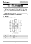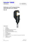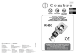
1
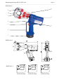
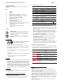
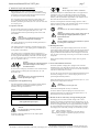
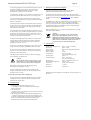
Bedienungsanleitung
Instruction Manual
EK 60 VPFT plus
Joh.-Christoph Schütz
HE.7932_J © 4/99
Serialnummer
HE7932_J.doc
∑ # 11
Bedienungsanleitung EK 60 VPFT plus
Seite 2
______________________________________________________________________________________________________________________
Bild/Picture 1
8
4
10
3
5
6
1
2
9
7
Bild/Picture 2
Bild/Picture 3
Preßkraft richtig
Preßkraft richtig
Preßkraft richtig
Bedienungsanleitung EK 60 VPFT plus
Seite 3
______________________________________________________________________________________________________________________
Tabelle 1 (siehe Bild 1 Seite 2)
Pos.- Bezeichnung
Funktion
Nr.
1
BedienungsAuslösung des Preßvorgangs
schalter
2
Rückstelltaste Taste zum Öffnen der Preßdorne im Fehler-,
bzw. Notfall
3
Bügel
Bügel mit integriertem feststehendem
Preßdorn
4
VerschlußBolzen zum verschließen des Preßkopfes
bolzen
5
Gehäuse
Ergonomisch geformtes Kunststoffgehäuse
6
Leuchtdioden- Kontrollinstrument zum Feststellen des
anzeige
Ladezustandes, eines Gerätefehlers und zur
Wartungsanzeige.
7
Akku
wiederaufladbarer 2,6 Ah NiMH Akku
(RA4)
8
Ring
Öse zum Sichern des Werkzeuges und/oder
zu Montagezwecken
9
Handschutz
Bügel zum Schutz der bedienenden Hand,
kein Transportgriff!
10
Preßdorne
3 bewegliche und ein stationärer Preßdorn
Bedienungsanleitung
für das elektro-hydraulische Preßgerät Typ EK 60 VPFT plus,
Seriennummer ...........................
Inhaltsangabe
1
2
3
4
4.1
4.2
4.3
5
5.1
5.2
5.3
5.4
5.5
5.6
6
7
8
Einleitung
Aufschriften
Gewährleistung
Beschreibung des elektro-hydraulischen Preßgerätes
Beschreibung der Komponenten
Kurzbeschreibung der wesentlichen Leistungsmerkmale des
Gerätes
Beschreibung der Leuchtdiodenanzeige
Hinweise zum bestimmungsgemäßen Gebrauch
Bedienung des Gerätes
Erläuterung des Anwendungsbereiches
Verarbeitungshinweise
Wartungshinweise
Hinweis zur Verwendung des Akkus und des Ladegeräts
Aufbewahrung und Transport des Preßgerätes
Verhalten bei Störungen am Preßgerät
Außerbetriebnahme/Entsorgung
Technische Daten
4.2 Kurzbeschreibung der wesentlichen Leistungsmerkmale des Gerätes
Symbole
- Das Gerät besitzt einen automatischen Rücklauf, der den Kolben nach
Erreichen der max. Preßkraft automatisch in die Ausgangslage
zurückfährt.
- Das Gerät ist mit einem Nachlaufstop ausgerüstet, der den Vorschub
nach Loslassen des Bedienungsschalters (Pos.-Nr. 1) sofort stoppt.
- Das Gerät ist mit einer Doppelkolbenpumpe ausgestattet, die durch
einen schnellen Vorschub und einen langsamen Arbeitshub
gekennzeichnet ist.
- Der Preßkopf ist stufenlos 360° um die Längsachse drehbar. Dieses
ermöglicht Montagen auch an sehr schlecht zugänglichen Stellen.
- Der Preßkopf besitzt Zentrierstifte, die ein automatisches Zentrieren
des Verbindungsmateriales im Preßkopf gewährleisten.
- Die EK 60 VPFT plus ist mit einer Mikroprozessor-Steuerung
ausgestattet, die den Motor nach vollendetem Preßvorgang abschaltet,
Serviceintervalle anzeigt, den Ladezustand des Akkus (Pos.-Nr. 7)
angibt und eine Fehlerdiagnose durchführt.
Sicherheitstechnische Hinweise
Bitte unbedingt beachten, um Personenund Umweltschäden zu vermeiden.
Anwendungstechnische Hinweise
Bitte unbedingt beachten, um Schäden am
Gerät zu vermeiden.
1.
Einleitung
Vor Inbetriebnahme Ihres Preßgerätes
lesen Sie sich die Bedienungsanleitung
sorgfältig durch.
Benutzen Sie dieses Gerät ausschließlich für den
bestimmungsgemäßen Gebrauch.
Das Preßgerät darf nur durch eine elektrotechnisch unterwiesene
Person bedient werden. Das Mindestalter beträgt 16 Jahre.
4.3 Beschreibung der Leuchtdiodenanzeige
Die Leuchtdiode (Pos.-Nr. 6) dient in Verbindung mit der
Steuerungselektronik zur Information über den Zustand des Akkus
(Pos.-Nr. 7) und des Werkzeuges. Im einzelnen leuchtet die Diode in
folgenden Fällen:
Diese Bedienungsanleitung ist während der gesamten Lebensdauer
des Gerätes mitzuführen.
Der Betreiber muß
- dem Bediener die Betriebsanleitung zugänglich machen und
- sich vergewissern, daß der Bediener sie gelesen und verstanden
hat.
2.
Signal
Aufschriften
1
Auf dem an dem Gehäuse angebrachten Typenschild finden Sie
Typbezeichnung, Herkunftsangabe und den Firmennamen. Auf der
gegenüberliegenden Seite des Gehäuses befindet sich ein
Aufkleber mit einer Kurzdarstellung der preßbaren Querschnitte
für Kupfer und Aluminium und der Preßkraft. Die Seriennummer
befindet sich auf dem Hydraulikzylinder zwischen dem Gehäuse
und dem Preßkopf. Am Preßkopf befindet sich ein Hinweis auf
eine mögliche Quetschgefahr bei Preßvorgängen und ein Hinweis
auf mögliche Fehler beim Verpressen.
3.
Zeitpunkt
Bedeutung
beim Einsetzen des Durchführung
Akkus
des Selbsttests
Nach dem
Akku leer
Arbeitsvorgang
Nach dem
Fehler oder
Arbeitsvorgang
Wartung fällig
Während der Dauer Gerät zu heiß
der Übertemperatur
Nach dem
Wartung fällig
Arbeitsvorgang
und Akku leer
Gewährleistung
Die Gewährleistung bei sachgemäßer Bedienung beträgt 12
Monate ab Lieferdatum.
4.
2
Dauer
wenige Sekunden
Blinken
20 Sekunden
Dauerleuchten
20 Sekunden
Blinken (2Hz)
20 Sekunden
Blinken (5Hz)
20 Sekunden
Leuchten und
Blinken
1
Beschreibung des elektro-hydraulischen Preßgerätes
4.1. Beschreibung der Komponenten
Das elektro-hydraulische Preßgerät mit unserer Typbezeichnung
EK 60 VPFT plus ist ein handgeführtes Gerät und besteht aus
folgenden Komponenten:
2
Anmerkungen:
- Blinkt die Leuchtdiode ab einem bestimmten Zeitpunkt immer am Ende eines
Arbeitsvorgangs für etwa 20 Sekunden, dann ist eine Wartung fällig. Das Gerät ist
baldmöglichst ins Werk einzuschicken.
- Beim Auftreten eines Fehlers blinkt die Leuchtdiode gleichfalls am Ende eines
Arbeitszykluses. Das Blinken zeigt in diesem Fall das Ansprechen der
elektronischen Sicherung an. Eine mögliche Ursache dafür ist der Versuch, einen
Zyklus mit einem unzulässig entleerten Akku durchzuführen. Tritt das Blinken
auch nach Auswechseln des Akkus weiterhin auf, liegt eine andere Störung vor
oder eine Wartung ist fällig. In diesen Fällen ist das Gerät ins Werk einzuschicken.
Wird das Gerät zu heiß schaltet sich das Gerät selbständig ab. Nach Absinken der
Temperatur ist das Gerät automatisch wieder einsatzbereit.
Bedienungsanleitung EK 60 VPFT plus
Seite 4
______________________________________________________________________________________________________________________
5.
Sollten andere Verbindungsmaterialien verpreßt werden müssen, ist eine
Rücksprache mit dem Werk zwingend erforderlich.
Hinweise zum bestimmungsgemäßen Gebrauch
Vor Arbeitsbeginn sind alle aktiven, d.h. stromführenden Teile im
Arbeitsumfeld des Monteurs freizuschalten. Ist dieses nicht
möglich sind entsprechende Schutzvorkehrungen2 für das Arbeiten
in der Nähe von unter Spannung stehenden Teilen zu treffen.
Achtung
Es dürfen keine unter Spannung stehenden Teile
verpreßt werden.
Bei der EK 60 VPFT plus handelt es sich um ein handgeführtes Gerät,
das nicht eingespannt werden darf. Es darf nicht für den stationären
Einsatz verwendet werden. UnterEinhaltung bestimmter Bedingungen
kann das Gerät auch stationär mit unserem Präsentationsständer EKST
betrieben werden. Die Bedingungen entnehmen Sie bitte der
Bedienungsanleitung des EKST.
Es sollte vor Arbeitsbeginn der Ladezustand des Akkus (Pos.-Nr.
7) überprüft worden sein3. Ein niedriger Ladezustand kann
beispielsweise an der Leuchtdiode (Pos.-Nr. 6) durch ein 20 s’iges
Aufleuchten am Ende einer Pressung erkannt werden.
5.1. Bedienung des Gerätes
Das Gerät ist nicht für den Dauerbetrieb geeignet. Es muß nach ca. 3040 Verpressungen hintereinander eine Pause von ca. 15 min eingelegt
werden, um das Gerät abzukühlen.
Zuerst wird der Verschlußbolzen (Pos.-Nr. 4) herausgezogen und
der Bügel (Pos.-Nr.3) aufgeklappt. Das Verbindungsmaterial wird
mittig zwischen den 4 Preßdornen positioniert.
Achtung
Bei zu intensivem Gebrauch kann es durch Erhitzung zu
Schäden am Gerät kommen.
Achtung
Bei einer außermittigen Verpressung kann es zu
Schäden an dem Preßkopf kommen!
Achtung
Beim Betrieb von Elektromotoren kann es zur
Funkenbildung kommen, durch die feuergefährliche oder
explosive Stoffe in Brand gesetzt werden können.
Anschließend wird der Preßkopf wieder vollständig geschlossen.
Die Betätigung des Bedienungsschalters (Pos.-No. 1) leitet den
Preßvorgang ein, der durch das Zusammenfahren der Preßdorne
(Pos.-Nr. 10) gekennzeichnet wird (Bild 2 Bewegungsrichtung C).
Ein Preßvorgang ist abgeschlossen, wenn die Preßdorne (Pos.-Nr.
10) zusammengefahren sind. Der Rücklauf des Kolbens erfolgt
automatisch nach Erreichen des max. Betriebsüberdruckes.
Achtung
Das elektrohydraulische Preßgerät darf nicht bei starkem
Regen oder unter Wasser eingesetzt werden.
5.3. Verarbeitungshinweise
Anschließend kann ein weiterer Preßvorgang vorgenommen
werden oder durch Öffnen des Bügels (Pos.-Nr. 3) das
Verbindungsmaterial aus dem Preßkopf herausgenommen werden.
Um die Einhaltung der erforderlichen Preßkraft des Werkzeuges zu
überprüfen, ist als Zubehör eine Lehre (TGVP) und Prüfzylinder (TS10)
erhältlich. Die Prüfzylinder müssen mittig in axialer Richtung in den
Preßkopf eingelegt und verpreßt werden. Anhand der Längen-änderung
des Prüfzylinders kann eine Aussage über die aktuelle Preßkraft
getroffen werden. (siehe Bild 3) Sind die Prüfzylinder ohne
Berücksichtigung der Verwerfungen zu lang oder zu kurz muß das
Werkzeug neu eingestellt werden.
Achtung
Vor Eingriff in den Preßkopf Akku gegen
unbeabsichtigtes Betätigen aus dem Gerät
entfernen.
Durch Drücken der Rückstelltaste (Pos.-Nr. 2) können im Fehler-,
bzw. Notfall die Preßdorne in die Ausgangsposition zurückgefahren werden (Bild 2 Stellung B).
Achtung
Der Preßvorgang kann jederzeit durch Loslassen
des Betätigungsschalters unterbrochen werden.
Bitte beachten Sie unbedingt die im Katalog Kapitel 12 angeführten
Montagehinweise.
5.4. Wartungshinweise
Das Preßgerät ist weitestgehend wartungsfrei. Nach 10.000
Verpressungen ist eine Wartung4 fällig, die über die Leuchtdiode (Pos.Nr. 6) angezeigt wird. Es ist nach jedem Gebrauch zu reinigen und
trocken zu lagern. Sowohl Akku als auch Ladegerät müssen vor
Feuchtigkeit und vor Fremdkörpern geschützt werden.
5.2. Erläuterung des Anwendungsbereiches
Das Preßgerät verfügt über Preßdorne (Pos.-Nr. 10), die kraftgesteuert ohne Werkzeugwechsel Klauke Cu- und AlVerbindungsmaterial verpressen können.
Tabelle 2
Verbindungsmaterial
RKS +Vb “Normalausführung” +
RKS für Schaltgeräte-Anschlüsse
RKS für feindrähtige Leiter
Im Rahmen des bestimmungsgemäßen Gebrauchs darf vom Kunden nur
der Akku (Pos.-Nr. 7) gewechselt werden.
Achtung
Geräteversiegelung nicht beschädigen!
Preßbereich
16 –300 mm²
Bei Beschädigung der Geräteversiegelung erlischt der Garantieanspruch.
16-300 mm²
Zur Kontrolle der erforderlichen Preßkraft kann über einen Meßadapter
(Art.-Nr. MAVP) in Verbindung mit unserem digitalem Anzeigegerät
TC1 die tatsächliche Preßkraft exakt ermittelt werden.
Andere Anwendungen auf Anfrage.
Abkürzungen: RKS – Rohrkabelschuhe, Vb – Verbinder,
QKS – Quetschkabelschuhe
5.5. Hinweis zur Verwendung des Akkus und des Ladegerätes
Das Ladegerät ist für 230 V/50-60 Hz ausgelegt. Neue Akkus müssen
vor dem erstmaligen Gebrauch geladen werden. Zur Aufladung des
Akkus wird der Stecker des Ladegerätes in die Steckdose und der Akku
in das Ladegerät eingesteckt. Die Ladezeit beträgt ca. eine Stunde. Der
Ladezustand des Akkus5 wird an der Leuchtdiode am Ladegerät
abgelesen.
Achtung
Es dürfen nur die in Tab. 2 genannten
Verbindungsmaterialien verpreßt werden.
4
2
Siehe DIN EN 50110-1
3
siehe Kapitel 5.5
siehe Kap. 4.3
Der Ladezustand des Akkus kann auch an der LED des Gerätes durch
Leuchten am Ende einer Pressung erkannt werden. Siehe Kap. 4.3.
5
Bedienungsanleitung EK 60 VPFT plus
Seite 5
______________________________________________________________________________________________________________________
grün:
rot:
blinken:
Akku ist aufgeladen
Akku wird gerade geladen.
Akku nicht vollständig eingeschoben oder Akku
zu heiß, ein akustisches Signal ertönt.
7.
Außerbetriebnahme/Entsorgung
Dieses Gerät fällt in den Geltungsbereich der Europäischen WEEE
(2002/96/EG) und RoHS Richtlinien (2002/95/EG), die in Deutschland
durch das Elektro- und Elektronikgerätegesetz (ElektroG) umgesetzt
wurden.
Ist der Ladevorgang abgeschlossen wechselt das Ladelicht wieder
auf grün, wobei gleichzeitig ein akustisches Signal 5 Sekunden
lang ertönt.
Die WEEE-Richtlinie schreibt die Sammlung und umweltgerechte
Verwertung der Elektro- und Elektronik-Altgeräte vor. Informationen
dazu finden Sie auf unserer Homepage www.klauke.com unter WEEE &
RoHS.
Es dürfen keine artfremden Akkus weder in dem Preßgerät noch
im Ladegerät verwendet werden.
Die RoHS Richtlinie untersagt nach dem 01/07/2006 neue Elektro- und
Elektronikgeräte in Verkehr zu bringen, die mehr als 0,1 Gewichtsprozent Blei, Quecksilber, sechswertiges Chrom, polybromiertes
Biphenyl (PBB) oder polybromierten Diphenylether (PBDE) oder mehr
als 0,01 Gewichtsprozent Cadmium je homogenem Werkstoff enthalten.
Laden Sie Ihren Akku auf, sobald die Geschwindigkeit Ihrer
Maschine merklich nachläßt, bzw. die Anzeige am Gerät (siehe
Kap. 4.3) auf einen leeren Akku hinweist. Laden Sie nicht
vorsichtshalber einen teilentladenen Akku nach.
Wenn Sie einen Akku aus einem kürzlich betriebenen Gerät oder
einen, der längere Zeit in der Sonne lag, laden, kann das
Aufladelicht rot blinken. Warten Sie in diesem Fall eine Weile.
Das Aufladen beginnt nach Abkühlung des Akku.
Akku’s (Pos.-Nr. 5) müssen unter Berücksichtigung der Batterieverordung speziell (getrennt) entsorgt werden.
Achtung
Das Gerät darf nicht im Restmüll entsorgt werden. Die
Entsorgung muß durch den Entsorgungspartner der Fa.
Klauke vornehmen werden.
Kontaktadresse: [email protected]
Blinkt das Aufladelicht abwechselnd rot und grün und wird ein
Warnsignal 20 sec. lang abgegeben, ist das Aufladen nicht
möglich. Die Pole des Ladegerätes oder die des Akkus sind durch
Staub verschmutzt oder der Akku ist verbraucht oder beschädigt.
Wollen Sie zwei Akkus nacheinander aufladen, warten Sie 15 min
bevor Sie den zweiten Akku laden.
Laden Sie den Akku bei einer Raumtemperatur von 10°C bis 40°C.
Lassen Sie das Ladegerät nie im Regen oder Schnee liegen. Laden
Sie den Akku nicht in Anwesenheit leicht entzündbarer Stoffe oder
Gase.
Tragen Sie das Ladegerät nie am Netzkabel und ziehen Sie es nicht
gewaltsam aus der Steckdose heraus. Stecken Sie keine fremden
Gegenstände in die Lüftungsgitter des Ladegerätes.
Das Laden der Akkus darf nur in den vom Hersteller
vorgeschriebenen Ladegeräten vorgenommen werden.
Achtung
Stecken Sie den Akku nicht in Ihre Hosentasche
oder in Ihre Werkzeugkiste, wenn sich in ihnen
leitfähige Teile befinden, wie z.B. Münzen,
Schlüssel, Werkzeuge oder andere metallische Teile.
Ziehen Sie den Stecker des Ladegerätes nach dem Laden aus der
Steckdose heraus. Nehmen Sie das Ladegerät nicht auseinander.
Um die Sicherheit und Zuverlässigkeit des Ladegerätes zu gewährleisten sollten Reparatur, Wartung oder Einstellung durch unser
Service-Center durchgeführt werden.
5.6. Aufbewahrung und Transport des Preßgerätes
Um das Preßgerät vor Beschädigungen zu schützen, muß es nach
Gebrauch und nachdem es gesäubert worden ist, in den Transportkoffer gelegt werden, der dann anschließend sicher zu verschließen
ist.
6.
Verhalten bei Störungen am Preßgerät
a.) Regelmäßiges Blinken der Leuchtdiodenanzeige (Pos.-Nr. 6)
=> Akku (Pos.-Nr. 7) austauschen. Leuchtet die Anzeige weiter,
muß das Gerät eingeschickt werden. (siehe auch Kap. 4.3)
b.) Das Preßwerkzeug verliert Öl.
=> Das Gerät einschicken. Das Gerät nicht öffnen und die
Geräte-versiegelung nicht entfernen.
c.) Preßwerkzeug erreicht den Enddruck nicht.
=> Preßvorgang unterbrechen. Rückstelltaste (Pos.-Nr. 2)
gedrückt halten und gleichzeitig Bedienungsschalter ca. 10 sec.
Dauerbetätigen. Wird der Fehler dadurch nicht behoben, muß
das Gerät ins Werk eingeschickt werden.
8.
Technische Daten
Gewicht des kompl. Gerätes:
Antriebskraft:
Antriebsmotor:
Akkuspannung:
Akkukapazität:
Akku-Ladezeit:
Preßzeit:
Pressungen pro Akku:
Hydrauliköl:
Umgebungstemperatur:
Schalldruckpegel:
Vibrationen:
Maße:
ca. 5,1 kg (inklusive Akku)
ca. 55 kN
Gleichstrom-Permanentfeldmotor
12 V
2,6 Ah [RA4]
ca. 1 h [LG 4], bzw. ¼ h [LG5]
ca. 5 s
ca. 150 Pressungen
(Cu 150 mm² DIN 46235)
ca. 65 ml "Shell Tellus T 15"
-20°C bis +40°C
70 dB (A) in 1m Abstand
< 2,5 m/s²
(gewichteter Effektivwert der
Beschleunigung)
Siehe Bild 2
Anmerkung
Diese Bedienungsanleitung kann jederzeit kostenlos unter der BestellNr. HE.7932_I nachbestellt werden.
Instruction Manual EK 60 VPFT plus
page 6
______________________________________________________________________________________________________________________
Table 1 (see Picture 1 page 2)
Pos.- Description Function
No.
1
Trigger
switch to start crimping procedure
2
Retract
button to retract the indenters in case of error
button
or emergency
3
Latch
Latch with integrated indenter
4
Locking pin Pin neccessary to close the crimping head
5
Housing
ergonomically formed plastic housing for
perfect handling with a detachable lid
6
Light diode indicator for tool functions and battery
display
charge control
7
Battery
rechargeable 2,6 Ah NiMH battery (RA4)
cartridge
8
Ring
Loop to secure the tool and/or for assembly
purposes
9
Removable guard to protect the operating hand, not for
hand guard transportation
10
Indenter
3 moving and 1 stationary indenter
Instruction Manual
for the electric-hydraulic crimping unit Type EK 60 VPFT plus,
Serial-No. ...........................
Index
1
2
3
4
4.1
4.2
4.3
5
5.1
5.2
5.3
5.4
5.5
5.6
6
7
8
Introduction
Labels
Warranty
Description of the electric-hydraulic crimping unit
Description of the components
Brief description of the important features of the unit
Description of the light diode display
Remarks in respect of the determined use
Operation of the units
Explanation of the application range
Mounting instructions
Service and Maintenance instructions
Remarks on the use of the Battery Cartridge and Charger
Storage and transport of the crimping unit.
Troubleshooting
Putting out of operation/waste disposal
Technical data
4.2. Brief description of the important features of the unit
- The hydraulic unit incorporates an automatic retraction which returns
the indenters into its starting position when the maximum operating
pressure is reached.
- The unit is equipped with a special brake which stops the forward
motion of the indenters when the trigger (Pos.-No. 1) is released.
- The unit is equipped with a double piston pump which is characterised
by a rapid approach of the indenters (Pos.-No. 10) towards the
connector and a slow crimping motion.
- The crimping head can be smoothly turned by 360° around the
longitudinal axis in order to gain better access to tight corners and
other difficult working areas.
- The crimping head incorporates guiding mechanism, respectively
centering pins, which provide an automatic centering of the
connecting material in the crimping head.
- The EK 60 VPFT plus is equipped with a microprocessor which
indicated service intervals, internal checks and low battery charges. It
also shuts off the motor automatically after the crimp is completed.
Symbols
Safety warnings
Please do not disregard these instructions in order to
avoid human injuries and environmental damages.
Operational warnings
Please do not disregard them to avoid damaging the
pump unit.
1.
Introduction
Before starting to use the tool please read the
instruction manual carefully.
Use this tool exclusively for its determined use.
4.3. Description of the light diode display
Mounting and assembly of connecting material with the help of
this tool must only be performed by specially trained personnel.
The minimum age is 16 years.
This tool is equipped with a special circuit board incorporating several
important features to inform the user about the current status of the unit.
The diode (Pos.-No. 6) signals in the following cases:
This instruction manual has to be carried along during the entire
life span of that tool.
2.
Signal
Duration
The operator has
- to guaranty the availability of the instruction manual for the user
and
- to make sure, that the user has read and understood the
instruction manual.
1
Labels
2
a few seconds of
flashing
glowing for
20 seconds
flashing for
20 seconds (2Hz)
flashing for
20 seconds (5Hz)
20 sec. glowing
and flashing
intermittently
On the labels fixed on the housing of the tool you’ll find the type
specification name of the manufacturer and the company logo. On
the opposite side of the housing you’ll find a label with a brief
presentation of the scope of manageable cross-sections for copper
and aluminium and the pressing force. The serial number is on the
hydraulic cylinder between the housing and the crimping head. On
the crimping head you’ll find a warning against possible injuries
during the crimping process and against crimping errors.
1
3.
Warranty
If correct operation is guaranteed our warranty is 12 months from
the time of delivery.
4.
Description of the electric-hydraulic crimping unit
4.1. Description of the components
The electric-hydraulic crimping unit type EK 60 VPFT plus is a
hand held tool and consists of the following components:
When it
occures
battery
insertion
after crimp
What it means
after crimp
return for service
During high
temperature
after crimp
unit too hot
self check – O.K.
battery discharged
service required
and battery flat
Remarks:
- Does the diode signal periodically at the end of a working cycle for
approx. 20 sec the unit must be returned to an authorised Service Center
for Service as soon as possible.
- In case of an error the light diode display also signals periodically at the
end of a working cycle. The signal indicates in this case the circuit opening
by the electronic fuse. A possible reason for that is that a cycle was
performed with an incorrectly low battery. If the signal occurs even after
changing the battery there must be a different error or a service is due. In
these cases the tool must be returned to the manufacturer or an authorised
service center.
2
The unit switches off when it gets too hot. It switches on automatically
after the unit cooled off.
Instruction Manual EK 60 VPFT plus
page 7
______________________________________________________________________________________________________________________
5.
Attention
Do not crimp on live cables or conductors
Remarks in respect of the determined use
Before starting any work on electrical appliances it must be
safeguarded that there are no live parts in the immediate assembly
area of the user. Is this not possible special precaution measures1
for working near live parts must be provided.
The EK 60 VPFT plus is a hand held tool and it is not supposed to be
restrained in a vise. It is not allowed to use the tool in a stationary
application. Complying certain conditions the unit can be operated
stationary with our presentation support EKST. The conditions can be
taken from the instruction manual of the EKST.
Prior to operating the unit the charging level of the battery (Pos.No. 7) should have been tested2. A low charging level can be
detected by the flashing of the LED (Pos.-No. 6) for 20 s at the end
of a crimping cycle.
The tool is not designed for continued crimping operations. After a
sequence of approximately 30-40 completed crimps you have to make a
break of 15 min. to give the tool time to cool down.
5.1. Operation of the unit
Attention
Too intensive use can cause heat damages for the tool
First the crimping head must be opened by pulling out the locking
pin (Pos.-No. 4) and removing the latch (Pos.-No. 3). The
connecting material must be positioned right in the center of the
four indenters.
Attention
During the operation of electric engines sparks can occur
which might ignite highly inflammable or explosive
liquids and materials
Attention
If the connector is crimped in an out-of-center
position the crimping head can damaged.
The crimping head has to be opened by unhooking the latch (Pos.No. 3 & Picture 2 Pos. A).
Attention
Electric-hydraulic crimping tools should not be operated
in pouring rain or under water.
5.3. Mounting instructions
The crimping procedure is initiated by actuating the trigger (Pos.No. 1 & Picture 2 Pos. C). The crimping process is defined by the
closing motion of the indenters.
In order to guaranty the required crimping force the user can order a
special gauge (TGVP) and test slugs (TS10). The slug must be centered
in the crimping head and crimped in axial direction. The difference in
length provides information about the actual crimping force of the tool.
(Pls. see picture 3) If the slugs are too long or too short the tool must be
re-adjusted.
The crimping process is terminated when the crimping force is
reached. After having completed the crimp the indenters return into
the starting position automatically. Afterwards a second crimping
cycle can be initiated or the it can be finished by opening the latch
(Pos.-No. 3 & Picture 2 Pos. A).
Please read the assembly instructions in Chapter 12 of our general
catalogue.
Attention
Before approaching the crimping head with 5.4 Service and maintenance instruction
your hands and fingers remove battery to
The electric-hydraulic crimping unit is equipped with a controller
avoid unintended use.
enabling the user to see when the next service is due. (Pls. read chapter
4.3 for more information) When the next service is due the unit must be
In case of error or emergency the indenters can be returned into the
returned to an authorised service center.
starting position by actuating the retract button (Pos.-No. 2 &
Picture 2 Pos. B).
For every day service the unit has to be cleaned and dried after each use.
The battery cartridge (Pos.-No. 7) and the charging unit have to be
Attention
protected against humidity and dust.
The crimping process can be interrupted at any
moment by releasing the trigger.
Within the determined use of the tool only the batteries (Pos.-No. 7) are
permitted to be changed by the customers.
5.2. Explanation of the application range
Attention
Do not damage the seals of the tool.
Our electric hydraulic crimping unit is a dieless crimper supplied
with four indenters to crimp primarily Klauke copper and
aluminium cable lugs and connectors.
If the seals are damaged the warranty is invalidated.
Table 2
Connectingmaterial
TCL + Connectors “Standardversion” +
TCL for switchgear connections
TCL for fine str. cables/conductors
In order to check the required crimping force of the tool use our
measuring adapter (Part.-No. MAVP) with our digital meter TC 1 to
determine the exact actual crimping force.
Range
16 –300 mm²
16-300 mm²
5.5 Remarks on the use of the battery cartridge and charging unit.
The charging unit is run with a nominal voltage of 230 V and a
frequency of 50-60 Hz. New batteries must be charged prior to use. To
charge the battery cartridge (Pos.-No. 7) the power plug of the charging
unit has to be plugged into the power supply and the battery cartridge
has to be pushed into the charging unit. The charging time is one hour.
The charging level of the battery cartridge can be checked by a LED4.
Other applications upon request.
Abbreviation: TCL – Tubular cable lugs
Attention
Do only crimp those connecting materials
mentioned in Tab. 2
green battery cartridge is charged
red
Battery cartridge is empty and is just being charged
flashing battery cartridge is not pushed in properly or too hot,
a sound signal occurs
If different conducting materials have to be crimped, please
contact the manufacturer.
1
2
See EN 50110-1
See Chapter 5.5 for more information of the battery and charging unit
4
The charging level of the battery can also be verified by the LED of the
tool at the end of a crimping cycle. See chapter 4.3 for further information.
Instruction Manual EK 60 VPFT plus
page 8
______________________________________________________________________________________________________________________
Is the battery plugged in correctly the LED changes from green to
red and the charging procedure starts. When the charging
procedure is terminated the LED changes again to green.
Simultaneously a signal occurs for 5 seconds.
7.
This unit is subjected to the scope of the European WEEE
(2002/96/EEC) and RoHS (2002/95/EEC) directives.
The WEEE directive regulates the collection and the environmental
friendly recycling of electro and electronic units. Information about this
can be found in our home page www.Klauke.com under ‘WEEE &
RoHS’.
No other battery cartridges e.g. dry batteries or car batteries etc. are
permitted to be used neither in the tool nor in the charging unit.
As soon as the speed of the machine decreases noticeably the
battery must be recharged. Do not recharge a partially discharged
battery as a precaution.
The RoHS directive bans new electrical and electronic equipment put on
the market which contains more than 0,1 weight percentage lead,
mercury, hexavalent chromium, polybrominated biphenyls (PBB) or
polybrominated diphenyl ethers (PBDE) and 0,01 weight percentage
cadmium per homogeneous material.
If charging a battery which has currently been used or which was
laying in the sun for a longer period of time the LED might flash
red. In this case wait for a while. The charging procedure starts
after the battery cooled down.
Battery cartridges (Pos.-No. 7) must be specially disposed of according
to the EEC Battery Guideline.
Does the LED flash red and green and does an audible tone occur
for 20 seconds it is not possible to charge that battery. The poles of
the battery or the charging unit are dirty or the battery is low or
damaged. If you want to charge two batteries in a row wait for 15
min before you charge the second battery.
Avoid great fluctuating temperatures under 0°C and above 40°C.
Through these fluctuations damages may result for the battery
cartridge as well as for the charging unit. The best operation
temperature is between 15-25 °C.
Do not leave or operate the charging unit in rain or snow. Do not
charge the battery near lightly inflammable materials or gases.
Do not use the cord to transport the charging unit or to pull the
plug out of a wall socket with force. Do not insert strange parts
into the ducts of the charging unit.
The charging of the batteries must only be done with charging
units supplied by the manufacturer.
Attention
Do not place the battery in your pocket or in your
toolbox if there are any conductive materials in it
such as coins, keys, tools or other metallic parts.
Pull the plug of the charging unit after charging. Do not
disassemble the charging unit or battery.
In order to safeguard a safe and proper performance of the
charging unit the repair and service of the unit should be made
through our Service Center.
5.6 Storage and transport of the crimping tool
In order to protect the tool against damages it has to be cleaned
carefully after each use and be put into the transportation case
which has to be closed safely.
6.
Troubleshooting
a.) Flashing of the light diode display (Pos.-No. 6)
=> See chapter 4.3 for more information about the special
functions of the tool.
b.) The tool loses oil.
=> Return the tool to the manufacturer. Do not open the tool and
damage the seals of the tool.
c.) The crimping tool does not reach the final operating pressure.
=> Stop the crimping process. Press the retract button (Pos.-No.
2) and the operating switch continuously and simultaneously for
about 10 sec. Is the malfunction not be eliminated by this
attempt the tool has to be returned to the manufacturer.
Putting out of operation/waste disposal
Attention
Do not dispose of the unit in your residential waste.
Klauke has no legal obligation to take care of their
WEEE outside Germany unless the product has been
shipped and invoiced from inside your country by Klauke.
Please contact your distributer to find out more how to
get your tool recycled environmental friendly.
8.
Technical Data
Weight of the complete tool:
Drive force:
Driving motor:
Battery voltage:
Battery capacity
Charging time:
Hydraulic oil:
Environmental temperature:
Sound level:
Vibrations:
approx. 5,1 kg (incl. battery)
approx. 55 kN
direct-current permanent field motor
12 V
2,6 Ah
approx. 1 h (LG4),
¼ h with Quickcharger (LG5)
approx. 5 s
approx. 150 crimps
(Cu 150 mm² DIN 46235)
approx. 65 ml "Shell Tellus T 15"
-20°C to –40°C
70 dB (A) in 1m distance
< 2,5 m/s²
Dimensions:
See Picture 2
Crimping time:
Crimp per battery:
Additional instruction manuals are available free of charge. The part # is
HE.7932_I.
Service EK 60 VPFT plus
Seite/page 9
______________________________________________________________________________________________________________________
SLOWENIEN
DEUTSCHLAND
FRANKREICH
GROßBRITANNIEN
ISRAEL
ITALIEN
NIEDERLANDE
ÖSTERREICH
POLEN/ UKRAINE
PORTUGAL
Klauke Remscheid
Mr. Radtke
Auf dem Knapp 46
42855 Remscheid
Tel.: ++49 (0)2191/907-168
Fax: ++49 (0)2191/907-242
E-Mail: [email protected]
KLAUKE FRANCE
Mr. Weiten
16, Rue Saint-Louis
Z.I. Actisud
57150 Creutzwald (France)
Tel.: 0033-3-87298470
Fax: 0033-3-87298479
E-Mail: [email protected]
SPANIEN/ ANDORRA:
Isaria d. o.o.
Ms. Zorz
Proizvdnja in trgovina Cece 2a
1420 Trbovlje (Slowenien)
Tel.: 00386-356-31800
Fax: 00386-356-31802
E-Mail: [email protected]
Gave Electro S.A.
Mr. Fernando Carvalho
Paratge Coll-Blanc, S/N
Aptdo. 12
08430 La Roca del Valles,
Barcelona (Spanien)
Tel.: 0034-93-8424887
Fax: 0034-93-8422755
E-Mail: [email protected]
FINNLAND
OYElteosähkö AB
Mr. Reijo Karlsson
Kärsämäentie 23,
20360 Turku (Finnland)
Tel.: 00358-2-4100220
Fax: 00358-2-4100288
E-Mail: [email protected]
SÜDARFIKA
Eberhardt Martin CC
Mr. Roger Martin
55 Evelyn Street
Newlands Johannesburg
Post point Delarey 2114
Tel.: 0027-11-2880000
Fax: 0027-11-6732043
E-Mail: [email protected]
AUSTRALIEN
(regional)
WAB
Mr. Roberto Aleotti
Via F.lli Rosselli 8
40121 Bologna (Italy)
Tel.: 0039-051-522308
Fax: 0039-051-522761
E-Mail: [email protected]
South West Hydraulics
Mr. Hari Goundar
12/38 Lancaster St
Ingeleburn NSW 2565 (Australia)
Tel.: 0061-2-96054199
Fax: 0061-2-9605 4261
E-Mail:
[email protected]
(regional)
H.K. Electric B.V.
Mr. Ferry Jansen
De Steegen 7
5321 JZ Hedel (Niederlande)
Tel.: 0031-73-5997599
Fax: 0031-73-5997590
E-Mail: [email protected]
Forcorp PTY Ltd.
Mr. Bill Westerman
7, Lookout Circle
Ellenbrook Western Australia 6069
Tel.: 0061-92969090
Fax: 0061-92969080
E-Mail: [email protected]
NEUSEELAND
Kasco Hydraulics Ltd.
Mr. John Kastermans
Unit B, 12 Dalgety Drive, Manukau
Po-box 75-466, Manurewa,Auckland
Tel.: 0064-9-2671300
Fax: 0064-9-2673170
E-Mail: [email protected]
Norwich Instrument Services
Mr. Norman Cockburn
32 Hellesdon Park Road
Drayton High Road
Norwich NR6 5DR (UK)
Tel.: 0044-1603-416900
Fax: 0044-1603-416902
E-Mail: [email protected]
Shay A.U., Ltd.
Mr. Shay
Ind. Zone Kiriat Arieh
Embar Street 23/25
P.O. BOX 10049
49222 Petach Tikva (Israel)
Tel.: 00972-3-9233601
Fax: 00972-3-9234601
E-Mail: [email protected]
Klauke Handelsgesellschaft mbH
Mr. Acham
Kaiser-Franz-Josef-Str. 9
1230 Wien (Österreich)
Tel.: 0043-1-8893436
Fax: 0043-1-8893433
E-Mail: [email protected]
RB Brexim S.A.
Marynin 7a
05-825 Grodzisk Mazowiecki (Polen)
Tel.: 0048-22-7344380
Fax: 0048-22-7344381
E-Mail: [email protected]
Palissy Galvani Electricidade S.A.
Ms. Anna Pereira
Rua Serpa Pinto, 15-A/B
1200-433 Lisboa (Portugal)
Tel.: 00351-21-3223400
Fax: 00351-21-3223410
E-Mail: [email protected]
TSCHECHISCHE REPUBLIK/
SLOVAKEI
Klauke z. Nitsch s.r.o.
Mr. Jiri Nitsch
M. Pujmanove 1220/31
14000 Praha 4 – Pankrac
(Tschechische Republik)
Tel.: 00420-261213229
Fax: 00420-261213218
E-Mail: [email protected]
SCHWEIZ
Ferratec AG
Mr. Bürgisser
Großmattstr. 19
CH-8964 Rudolfstetten
Tel.: 0041-56-6492121
Fax: 0041-56-6492141
E-Mail: [email protected]
Service EK 60 VPFT plus
Seite/page 10
______________________________________________________________________________________________________________________
VOLKSREP. CHINA
Greenlee Textron Shanghai Office
Add: Floor 6th, Lippo Plaza,
No. 222 Huai Hai M. Rd, Shanghai,
200021, China
Tel: 86-21-5396 6555 ext.108
Fax: 86-21-5396 6913
Hotline: 800 820 0317
E-Mail: [email protected]
KROATIEN
Konekt d.o.o.
Mr. Dubravko Salkovic
Cerinina 4
HR-10000 Zagreb (Kroatien)
Tel.: 00385-12361890
Fax: 00385-12361882
E-Mail: [email protected]
LIBANON
Al-Bonian Group
Mr. Sleiman
Tayouneh,Al-Ghazaleh Building
P.O. Box 13
6470 Beirut-Lebanon (Libanon)
Tel.: 00961-1-385 708
Fax: 00961-1-385 714
E-Mail: [email protected]
INDIA
STI Industries
Ms. Supriti Sharma
208, Dhamji Shamji
Udyog Bhavan
Veera Desai Road, Andheri (W)
Mumbai 400058 (India)
Tel.: 0091-22-26744096
Fax: 0091-22-26744044
E-Mail:[email protected]
VIETNAM
Huu Hong Machinery Co., Ltd
Mr. Thach Vu Ngoc Trang
157-159 Xuan Hong Street
Ward 12, Tan Binh District
Ho Chi Minh City (Vietnam)
Tel.: 0084-8-8117454
Fax: 0084-8-8116338
E-Mail: [email protected]
TAIWAN
Po Charng Co.Ltd
Mr. Vincent Chen
No. 166, Sung Sin Road
Sun Yi Dist, Taipei 110 (Taiwan)
Tel.: 0084-886227631623
Fax: 0084-886227667492
E-Mail: [email protected]
JAPAN:
Osaka Hydraulics
Mr. Ryoji Furuya
10-32 Egasaki -cho Tsurumi-ku,
Yokohama 30-0002 (Japan)
Tel.: 0081-45-5703830
Fax: 0081-45-5703831
E-Mail: [email protected]
Shanghai FengYe Trading Co., Ltd
Add: Area D, No. 8 Lane 1340, Jing
Sha Jiang Rd, Shanghai , 200233,
China
Tel: 86-21-5265 8803
Fax: 86-21 5265 8829
E-Mail: [email protected]
KOREA
SCHWEDEN
NORWEGEN
UNGARN
TÜRKEI
Schweden
Bulgarien
RUSSLAND
RUMÄNIEN
Taehyung Hydraulic Tool
Mr. Kim
140-5, Gamjeun-Dong, Sasang-Gu
Busan 17-060 (Korea)
Tel.: 0082-51-3171507
Fax: 0082-51-3171507
E-Mail: [email protected]
Miltronic AB
Mr. Thomas Fred
Kungshagsvägen 7
S-611 29 Nyköping (Schweden)
Tel.: 0046-155-77700
Fax: 0046-155-77702
E-Mail: [email protected]
Miltronic AS
Mr. Hans Petter Selbo
Dolasletta 5, 3408 Tranby
N-3421 Lierskogen (Norwegen)
Tel.: 0047-32226610
Fax: 0047-32226656
E-Mail:
[email protected]
Trend Elektro
Mr. Istvan Imrik
H-1117 Budapest
Dombovari ut 5-7 (Ungarn)
Tel.: 0036-1-464-3118
Fax: 0036-1-464-3119
E-Mail: [email protected]
Ünal Kardes
Mr. Servet Diricanli
Eski Londra Asfalti No. 6
34630 Besyol-SefaköyIstanbul (Türkei)
Tel.: 0090-212-6249204
Fax: 0090-212-5924810
E-Mail: [email protected]
Unit Mark Pro
Mr. Alexander Tarasov
109147 Moscow
Marksistskaya 34, bldg 10
(Russland)
Tel.: 007-495-7480907
Fax: 007-495-7480909
E-Mail: [email protected]
Gerkon S.R.L.
Mr. Heim
Miercurea Ciuc,
str.G. Cosbuc nr.45
(Rumänien)
Tel.: 0040-266-372108
Fax: 0040-266-312238
E-Mail: [email protected]
Gelante (planned) Service-Center in 2007
Serbia + Montenegro,
Irland
Auf dem Knapp 46
D-42855 Remscheid
__________________________________________________________________________________________________________________
Handgeführtes Elektrowerkzeug Typ EK 60 VPFT plus
(D) CE `99 - Konformitätserklärung. Wir erklären in alleiniger
Verantwortlichkeit, daß dieses Produkt mit den folgenden Normen oder
normativen Dokumenten übereinstimmt:
DIN EN 60745-1, DIN EN 292 Teil 1 und 2, EN 294, EN 349, EN
60204-1, EN 28662-1, EN 50081-1, EN 50082-2, EN 60529
gemäß den Bestimmungen der Richtlinien 98/37/EWG, 89/336/EWG
(DK) CE `99 - Konformitetserklæring. Vi erklærer under almindeligt
ansvardt at dette produkt er i overensstemmelse med folgende normer
eller normative dokumenter:
EN 60745-1, EN 292 Teil 1 und 2, EN 294, EN 349, EN 60204-1, EN
28662-1, EN 50081-1, EN 50082-2, EN 60529
i henhold til bestemmelseme i direktiverne 98/37/EØF, 89/336/EØF
(GB) CE `99 - Declaration of conformity. We declare under our sole
responsibility that this product is in conformity with the following
standards or normative documents:
EN 60745-1, EN 292 Teil 1 und 2, EN 294, EN 349, EN 60204-1, EN
28662-1, EN 50081-1, EN 50082-2, EN 60529
in accordance with the regulations of directives 98/37/EEC,
89/336/EEC
(PL) CE `99 - Zgodnosc z dyrektywami CE. Swiadomi
odpowiedzialnosci oswiadczamy, ze niniejszy produkt jest zgodny z
nastepujacymi normami lub dokumentacja normatywna:
EN 60745-1, EN 292 Teil 1 und 2, EN 294, EN 349, EN 60204-1, EN
28662-1, EN 50081-1, EN 50082-2, EN 60529
zgodnie z postanowieniami wytycznych 98/37/EWG, 89/336/EWG
(F) CE `99 - Déclaration de conformité. Nous déclarons sous notre
seule reponsabilité que ce produit est en conformité avec les normes ou
documents normatifs suivants:
EN 60745-1, EN 292 Teil 1 und 2, EN 294, EN 349, EN 60204-1, EN
28662-1, EN 50081-1, EN 50082-2, EN 60529
conformément aux réglementations des directives 98/37/CEE,
89/336/CEE
(NL) CE `99 - Konformiteitsverklaring. Wij verklaren en wij stellen
ons er alleen voor verantwoordelijk dat dit produkt voldoet aan de
volgende normen of normatieve documenten:
EN 60745-1, EN 292 Teil 1 und 2, EN 294, EN 349, EN 60204-1, EN
28662-1, EN 50081-1, EN 50082-2, EN 60529
overeenkomstig de bepalingen van de richtlijnen 98/37/EEG,
89/336/EEG
(I) CE `99 - Dichiarazione di conformità. Dichiariamo sotto la nostra
esclusiva responsabilità
che questo prodotto è conforme alle seguenti norme e documenti
normativi:
EN 60745-1, EN 292 Teil 1 und 2, EN 294, EN 349, EN 60204-1, EN
28662-1, EN 50081-1, EN 50082-2, EN 60529
conformemente alle disposizioni delle direttive 98/37/CEE,
89/336/CEE
(E) CE `99 - Declaración de conformidad. Declaramos bajo nuestra
sola responsabilidad que este producto està en conformidad con las
normas o documentos normativos siguientes:
EN 60745-1, EN 292 Teil 1 und 2, EN 294, EN 349, EN 60204-1, EN
28662-1, EN 50081-1, EN 50082-2, EN 60529
de acuerdo con las regulaciones de las directivas 98/37/CEE,
89/336/CEE
(P) CE `99 - Declaração de conformidade. Declaramos sob nossa
exclusiva responsabilidade que este producto cumpre as seguintes
normas ou documentos normativos:
EN 60745-1, EN 292 Teil 1 und 2, EN 294, EN 349, EN 60204-1, EN
28662-1, EN 50081-1, EN 50082-2, EN 60529
conforme as disposiçoes das directivas 98/37/CEE, 89/336/CEE
(S) CE `99 - Konformitetsdeklaration. Vi förklarar pá eget ansvar att
denna produkt õverenstämmer med följande normer eller normativa
dokument:
EN 60745-1, EN 292 Teil 1 und 2, EN 294, EN 349, EN 60204-1, EN
28662-1, EN 50081-1, EN 50082-2, EN 60529
enligt bestãmmelserna i direktiverna 98/37/EG, 89/336/EG
(FIN) CE `99 - Todistus slandardinmukaisuudesta. Asiasta vastaavana
todistamme täten, että tämä tuote on seuraavien standardien ja
standardoimisasiakirjojen vaatimusten mukainen:
EN 60745-1, EN 292 Teil 1 und 2, EN 294, EN 349, EN 60204-1, EN
28662-1, EN 50081-1, EN 50082-2, EN 60529
ja vastaa säädoksiä 98/37/EU, 89/336/EU
(N) CE `99 - Konformitetserklæring. Vi erklærer på eget ansvarlighet
at dette produkt er i overensstemmelse med følgende standarder eller
standard-dokumenter:
EN 60745-1, EN 292 Teil 1 und 2, EN 294, EN 349, EN 60204-1, EN
28662-1, EN 50081-1, EN 50082-2, EN 60529
i henhold til bestemmelsene i direktive ne 98/37/EØF, 89/336/EØF
(GR) CE `99 - ∆ΗΛΩΣΗ ΣΥΜΜΟΡΦΩΣΗΣ Με αναληψη
συνολικης δηλωνοµε. οτι το πορον προιον συµϕωνει µε τα
παρακατω ποοτυπα και µε τα ηροτυηα ηου αναϕερονται στα
σχεπκο εγγραϕα
EN 60745-1, EN 292 Teil 1 und 2, EN 294, EN 349, EN 60204-1, EN
28662-1, EN 50081-1, EN 50082-2, EN 60529
συµϕωνα µε τοχς κονονισµους 98/37/EEC, 89/336/EEC
(H) CE `99 – Megfelelőségi nyilatkozat. Kéziműködtetésű elektromos
kéziszerszámok:
Teljes felelősségel kijelentjük, hogy ezek a termékek a következő
szabványokkal és irányelvekkel összhangban vannak:
EN 60745-1, EN 292 Teil 1 und 2, EN 294, EN 349, EN 60204-1, EN
28662-1, EN 50081-1, EN 50082-2, EN 60529
és megfelelnek a rendeltetés szerinti 98/37/EEC, 89/336/EEC
irányelveknek.
(CZ) CE `99 – Prohlášeni o shode. Prohlašujeme na vlastni
zodpovednost, ze tyto produkty splnuji následujici normy nebo
normativni listiny:
EN 60745-1, EN 292 Teil 1 und 2, EN 294, EN 349, EN 60204-1, EN
28662-1, EN 50081-1, EN 50082-2, EN 60529
Ve shode se smernicemi 98/37/EEC, 89/336/EEC
(RO) CE `99 - Declaraţie de conformitate. Noi declarăm pe propria
răspundere că acest produs este în conformitate cu următoarele norme
şi documente normative:
EN 60745-1, EN 292 Teil 1 und 2, EN 294, EN 349, EN 60204-1, EN
28662-1, EN 50081-1, EN 50082-2, EN 60529
potrivit dispoziţiilor directivelor 98/37/EEC, 89/336/EEC
Remscheid, den 19.02.2007
_____________________________________________
Dipl.-Ing. Joh.-Christoph Schütz, CE-Beauftragter