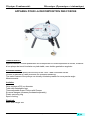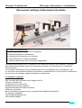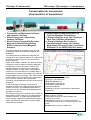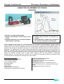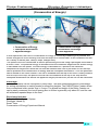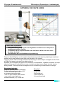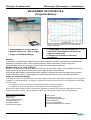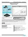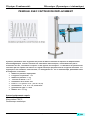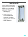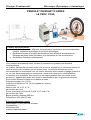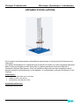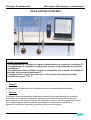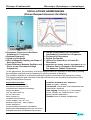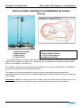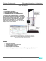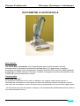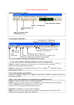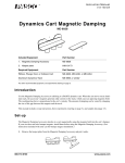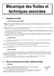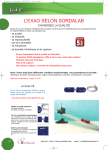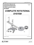
1
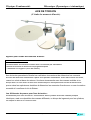
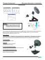
Physique Fondamentale Mécanique (Dynamique et cinématique) EXPERIENCE DE PHYSIQUE FONDAMENTALE MECANIQUE (DYNAMIQUE ET CINEMATIQUE) INTRODUCTION AU SYSTEME MECANIQUE (INTRODUCTORY MECHANICS SYSTEM) ESLI, Tel : 021 85 60 65 Fax : 021 85 58 88 E-mail : [email protected] Site web : www.esli.com.dz A.1.1 Physique Fondamentale Mécanique (Dynamique et cinématique) Typical Experiments Experience Typique Basic Experiments: Experiences De Base : 1. Measuring Forces: Hooke’s Law 2. Adding Forces: Resultants and Equilibrants 3. Resolving Forces: Components 4. Torque: Non-parallel Forces 5. Torque: Parallel Forces 6. Center of Mass 1. Mesure de Force: Loi de Hooke 2. Sommation des Forces : Forces Résultantes 3. Resolving Forces: Components 4. Moment: Forces Parallèle. 5. Moment: Forces non Parallèle. 6. Center of mass. Advanced Experiments: Experiences De Base : 7. Equilibrium of Physical Bodies 8. Forces on an Inclined Plane 9. Sliding Friction 10. Simple Harmonic Motion: Mass on a Spring 11. Simple Harmonic Motion: the Pendulum 7. L’équilibre des corps physique. 8. Les Forces Sur Les Plan Incliné. 9. Frottement Par Glissement. 10. Mouvement Harmonique Simple : Masse sur le ressort. 11. Mouvement Harmonique Simple : pendule. Simple Machines: 12. The Lever 13. The Inclined Plane 14. The Pulley 15. Designing a Balance Beam Machines Simple : 12. 13. 14. 15. The Level Plan incliné. La poulie. Concevoir une Poudre de Balance. Includes: Experiment Board: 40 x 45 cm; porcelain-coated steel surface. Spring Balance: calibrated in Newtons, g and cm with zero adjust Three Pulleys: 2 small, 1 large Degree Scale: with holding pin and force ring Torque Wheel: with 4 torque Indicators Balance Bar: with pivot and 2 sliding hooks Inclined Plane: with plumb bob and degree scale Rolling Mass: with two-way bracket Friction Block: variable area; wood and Teflon surfaces Planar Mass: for center of mass Measurements Double Pulley Block: for block and tackle experiments Three Mass Hangers: 5 g Brass Masses: 2 x 100 g, 2 x 50 g,4 x 20 g, 2 x 10 g Thread Experiment Manual: fully illustrated with worksheet-style experiments ESLI, Tel : 021 85 60 65 Fax : 021 85 58 88 E-mail : [email protected] Site web : www.esli.com.dz A.1.2 Physique Fondamentale Mécanique (Dynamique et cinématique) APPAREIL POUR LA DECOMPOSITION DES FORCES Table de forces : Appareil destiné à l'étude quantitative de la composition et la décomposition de forces, constitué d'une plaque de travail circulaire sur pied stable, avec double graduation angulaire Accurate Results: The ultra-low friction pulleys are the key to the Force Table’s accurate results. Friction is reduced to a bare minimum for increased sensitivity. The swivel feature of the pulleys can virtually eliminate parallax for more precise angle Measurements. Includes: Write-on/wipe-off 25 cm diameter Table with detachable legs Three adjustable Super Pulleys with Clamps Six mass hangers (masses purchased separately) Plastic centering ring Spool of string Required: Mass and Hanger Set ESLI, Tel : 021 85 60 65 Fax : 021 85 58 88 E-mail : [email protected] Site web : www.esli.com.dz A.1.3 Physique Fondamentale Mécanique (Dynamique et cinématique) Mouvement rectiligne Uniformément Accélérés Thèmes des expériences : Mouvement Linéaire Uniforme et Accélérés. Impacts Elastiques et Inélastiques. Conservation du Moment et de l'énergie Vitesse Moyenne et Vitesse Instantané Etude du Mouvement avec des frictions négligeables Développé spécialement pour l'introduction aux expériences de base en mécanique. Idéal pour des expériences pratiques grâce à sa construction robuste et une structure qui ne nécessite aucun entretien. Pour l'analyse quantitative des lois fondamentales de la cinématique et de la dynamique, par ex. mesure de mouvements constants et accélérés, accélérations sur un plan incliné, conservation du moment et de l'énergie, impacts élastiques et inélastiques. L’ensemble comprend: Rail a coussin d'air à section carré, longueur de 2m Chariot a coussin d'air Accessoire pour coussin d'air Soufflerie et tuyau de ronflement Dispositif de lancement câble connexion Câbles de connexion Boite avec bouton poussoir pour la commande du dispositif de lancement Un compteur intelligent Cellules photoélectriques (2) Alimentation stabilisé ESLI, Tel : 021 85 60 65 Fax : 021 85 58 88 E-mail : [email protected] Site web : www.esli.com.dz A.1.4 Physique Fondamentale Mécanique (Dynamique et cinématique) TABLE A COUSSIN D’AIR Thèmes des expériences : Lois du mouvement de Newton Conservation du moment et de l'énergie Impacts élastiques et inélastiques avec masses identiques et différentes Mouvements harmoniques et mouvements harmoniques couplés Trajectoires Répulsion magnétique La table à coussin d'air présente une surface plane en verre sur laquelle repose le papier d'enregistrement et carbone. De l'air comprimé est conduit vers les palets à travers des tuyaux Légers. L'air s'échappe sous le palet et laisse graviter celui-ci au-dessus du papier d'enregistrement. Le mouvement du palet est marqué par un enregistrement à étincelles. Dans les tuyaux d'air se trouvent de fines chaînes métalliques qui établissent la liaison avec le générateur d'étincelles. Au contact du palet, une étincelle se forme au milieu de celui-ci et laisse une trace sur le papier d'enregistrement. Comme les palets ont un poids de 550 grammes, leur mouvement n'est pas atténué par les tuyaux ni le fil à étincelles. L’ensemble comprend: 1 table d'expériences avec surface en verre, 580x580 mm 1 générateur d'étincelles avec interrupteur au pied 1 compresseur avec tuyau 2 palets en acier, diamètre 75 mm, 550 g 2 colliers pour palet, avec fermeture velcro 2 ressorts 1 poids additionnel pour palet, 150 g 1 galet de renvoi, diamètre 45 mm 1 barre médiane avec ventouse 1 jeu de papier d'enregistrement 1 mode d'emploi en anglais ESLI, Tel : 021 85 60 65 Fax : 021 85 58 88 E-mail : [email protected] Site web : www.esli.com.dz A.1.5 Physique Fondamentale Mécanique (Dynamique et cinématique) LOI DE NEWTON (Newton Law) Newton's First Law (Inertia) Newton's Second Law (F = ma) Newton's Third Law (FAB = -FBA) La Première Loi De Newton La Deuxième Loi De Newton La Troisième Loi De Newton Method: Students use this collection of equipment to discover or experimentally determine all three of Newton's Laws. Newton's First Law -- Students use a Motion Sensor to collect data for various sliding, rolling and hovering objects. Using the data and their observations, students better understand that an object's motion will not change unless acted upon by an external net force. Newton's Second Law -- Students use a Force Sensor and Motion Sensor with Dynamics System to discover the relationships between force, mass and acceleration. Newton's Third Law -- Using two Force Sensors, students prove that forces between objects are equal in magnitude yet opposite in direction. These experiments include both tug-of-war exercises and collisions between cars. Advantage: Using this set of equipment and probeware, students will better understand all three of Newton’s Laws. The integration between the probeware and equipment helps students focus on the physics of each experiment. Expriment Includes: PAScar Dynamics System Force Sensor (2) Motion Sensor Hover Puck Discover Friction Accessory Smart Pulley with Clamp Mass and Hanger Set Physics String Newton’s Laws Experiment Manual DataStudio File for Newton’s Laws Experiment Data Studio Lite Software Scientific workshop 500 interface : Ports: 2 Digital, 3 Analog Connection: Serial (also USB compatible with USB/Serial Converter) Data logging: Collect up to 17,000 Analog (force, voltage, etc.) data points or 7,000 Motion Sensor data points Portable: Built-in battery compartment ESLI, Tel : 021 85 60 65 Fax : 021 85 58 88 E-mail : [email protected] Site web : www.esli.com.dz A.1.6 Physique Fondamentale Mécanique (Dynamique et cinématique) Conservation du mouvement (Conservation of momentum) Conservation of Momentum in Elastic and Inelastic Collisions Kinetic Energy not Conserved in Inelastic Collisions Kinetic Energy Temporarily Stored as Magnetic Potential Energy During Elastic Collisions Using Magnetic Bumpers The total momentum and total energy of carts undergoing elastic and inelastic collisions are measured. The values before and after the collisions are compared to verify that momentum is conserved in all collisions while energy is only conserved in elastic collisions. Elastic and inelastic collisions are performed with 2 dynamics carts of different masses. Magnetic bumpers are used in the elastic collision and Velcro® bumpers are used in the completely inelastic collision. In both cases, momentum is conserved. Cart velocities are recorded using 2 Rotary Motion Sensors connected to the carts by string wrapped around pulleys. This measurement method adds very little friction to the experiment and, since the velocities are continuously monitored, any deceleration due to friction can be measured. A real-time graph of velocity versus time is obtained for each cart, clearly showing when the collision occurred. This enables the student to determine the cart velocities immediately before and after the collision. The kinetic energy before and after the collision is also studied. Kinetic energy is not conserved for inelastic collisions. It is also demonstrated that kinetic energy momentarily decreases during the elastic collision and then returns to the original value after the collision. Conservation Du Mouvement Dans La Collision Elastique Et Inélastique. L’Energie Cinétique n’est Pas Conservée Dans Les Collisions Inélastiques L’Energie Cinétique Est Conservée Temporellement Comme Un Potentiel Magnétique D’Energie Durant La Collision Elastique Par Un PARE-CHOCS D’aimant Experiment Includes: 2.2 m PAScar Dynamics System Dynamics Track Mount (2) RMS/IDS Adapters (2) Rotary Motion Sensors (2) onservation of Momentum Experiment Manual DataStudio File for Conservation of Momentum Experiment Scientific workshop 750 interface: Ports: 2 Digital, 3 Analog Connection: Serial (also USB compatible with USB/Serial Converter) Data logging: Collect up to 17,000 Analog (force, voltage, etc.) data points or 7,000 Motion Sensor data points Portable: Built-in battery compartment ESLI, Tel : 021 85 60 65 Fax : 021 85 58 88 E-mail : [email protected] Site web : www.esli.com.dz A.1.7 Physique Fondamentale Mécanique (Dynamique et cinématique) VARIATION DU MOMENT ET FORCE (Impulse) Impulse: Change in Momentum Impulse: Area Under a Force Versus Time Curve Different Shaped Force Curves for Elastic and Inelastic Collisions Changement Du Moment Surface Sous Pression En Fonction Du Temps. Les Différentes Formes Des Courbes De La Collision Elastique et Inélastique In this experiment, the impulse on a cart is determined in two ways, by measuring the change in velocity and by finding the area under a force versus time curve.A cart runs down a slightly inclined track and collides with a Force Sensor equipped with either a clay bumper, spring bumper or magnetic bumper. To determine the change in momentum (impulse), the speeds before and after the collision are recorded with a photogate. The photogate is also used to trigger the beginning of data collection for the Force Sensor. To confirm the impulse, the force versus time is plotted and the impulse is determined by finding the area under the curve. Different shaped curves of force versus time are obtained for the different bumpers. The spring and magnetic bumpers result in nearly elastic collisions while the clay produces a completely inelastic collision. The area under the clay force curve is half the area under the spring or magnetic force curves because the cart does not rebound in the clay collision. Experiment Includes: Scientific workshop 500 interface : 1.2 m PAScar Dynamics System Force Accessory Bracket IDS Photogate Bracket Photogate Head Force Sensor Picket Fence Impulse Experiment Manual DataStudio File for Impulse Experiment Ports: 2 Digital, 3 Analog Connection: Serial (also USB compatible with USB/Serial Converter) Data logging: Collect up to 17,000 Analog (force, voltage, etc.) data points or 7,000 Motion Sensor data points Portable: Built-in battery compartment ESLI, Tel : 021 85 60 65 Fax : 021 85 58 88 E-mail : [email protected] Site web : www.esli.com.dz A.1.8 Physique Fondamentale Mécanique (Dynamique et cinématique) CONSERVATION D’ENERGIE (Conservation of Energie) Conservation of Energy Centripetal Acceleration Apparent Weight Conservation D’Energie Accélération Centrifuge Poids Apparent. In this experiment, the Law of Conservation of Energy is verified by measuring the potential and kinetic energies for a car traveling over hills and loops on a curved track. A car is started from rest on a variety of tracks (hills, valleys, loops, straight track). The speed of the car is measured at various points along the track using a photogate connected to a Smart Timer. The potential energy is calculated from the measured height and the kinetic energy is calculated from the speed. The total energy is calculated for 2 points on the track and comparedThe height from which the car must be released from rest to just make it over the loop can be predicted from conservation of energy and the centripetal acceleration. Then the prediction can be tested on the roller coaster. If the car is released from the top of the hill so it easily makes it over the top of the loop, the speed of the car can be measured at the top of the loop and the centripetal acceleration as well as the apparent weight (normal force) on the car can be calculated. Advantage: The Roller Coaster can be configured in many ways. The white board background is convenient for writing calculations or making marks for measuring heights. The PASCO Roller Coaster differs from conventional roller coaster toys in 3 ways: The speed and height of the Roller Coaster car can be easily measured, the loss of energy due to friction is generally only about 5% and the cars will withstand repeated drops to the floor. Experiment Includes: Complete Roller Coaster System Photogate Heads (2) Smart Timer Conservation of Energy Experiment Manual ESLI, Tel : 021 85 60 65 Fax : 021 85 58 88 E-mail : [email protected] Site web : www.esli.com.dz A.1.9 Physique Fondamentale Mécanique (Dynamique et cinématique) APPAREIL DE CHUTE LIBRE Thèmes des expériences : Enregistrement point par point du diagramme de distance et de temps d’un mouvement accéléré régulier. Confirmation de la proportionnalité entre la distance de la chute et le carré du temps de chute. Détermination de l’accélération de la pesanteur g. Discover Freefall System can be used to drop almost any small object by attaching a small steel washer with a small adhesive pad (both are included in the system). Using an electric switch, timing is started automatically just as the object is dropped and the Timeof-Flight Pad stops timing when the object strikes it. Students can investigate the effect of air resistance on acceleration. In addition, students can drop objects of the same size but different mass to study how object mass affects terminal velocity during freefall. The drop box has a magnetic mount for attaching to metal frames in ceilings. Experiment Includes: Drop box Release labels for attaching Control cable washers to object (50) Control box Small nylon ball AC adapter large plastic ball Time-of-Flight receptor pad Golf ball Timer Switch Hollow golf ball Release washers (10) 1” steel ball Required: Smart timer Large base 25cm steel rod 100cm steel rod Universal bosshesd ESLI, Tel : 021 85 60 65 Fax : 021 85 58 88 E-mail : [email protected] Site web : www.esli.com.dz A.1.10 Physique Fondamentale Mécanique (Dynamique et cinématique) APPAREIL DE CHUTE LIBRE (Free fall apparatus) In order to ensure as good an electrical contact as possible the contact plates and the steel ball are gold plated, and they should be kept perfectly clean. They can be cleaned using an organic solvent such as alcohol. Thin cotton gloves can be used to avoid problems due to sweat from fingers and hands. Purpose: The goal of this experiment is to determine the acceleration of gravity g. Experimental setup: Measurements of corresponding values of fall time and height permit the determination of the acceleration of gravity using the equation: Procedure: The experimental setup is shown in the Figure. Position the strike plate directly under the release mechanism. Cock the release mechanism (1). Place the steel ball in the depression (5) between the contact plates (4) on the release mechanism. Release the steel ball using the push button (3). The timer starts. When the steel ball hits the strike plate, the timer stops. The fall height s is measured using a ruler as the distance from the lower edge of the ball (when ready for release) to the upper surface of the strike plate. Parallax error can be avoided by using the mirror provided. The experiment should be repeated using various values of the fall height, and corresponding values of height and time should be noted, e.g. by typing them directly into an Excel spreadsheet. It is then a simple matter to compute values of the acceleration of gravity. Required Equipment: 1980.10 Free Fall Apparatus 1 pcs. 2002.60 Student timer or equiv. 1 pcs. Retort stand and cables ESLI, Tel : 021 85 60 65 Fax : 021 85 58 88 E-mail : [email protected] Site web : www.esli.com.dz A.1.11 Physique Fondamentale Mécanique (Dynamique et cinématique) MOUVEMENT DE PROJECTILE (Projectile Motion) Independence of x and y Motion Muzzle Velocity vs. Time of Flight Angle vs. Horizontal Range L’Indépendance Du Mouvement Sur x et y Vitesse De Lancement En Fonction Du temps De Projection L’Angle En Fonction De l’Etendue Horizontale Method: In this series of experiments, students use a projectile launcher to better understand the kinematics and dynamics of projectile motion. Since measurements for these experiments involve single point measurements of time or velocity, the Smart Timer is the ideal timing instrument. Muzzle Velocity vs. Time of Flight: Students fire the projectile at three different velocities from the same height. The Photogate and Time of Flight Accessory are used to measure the time of flight at each muzzle velocity. Students are also asked to use the kinematics equations to predict the horizontal range given a launch angle and muzzle velocity. Carbon paper and a bulls-eye can then be used to test their hypothesis. Angle vs. Horizontal Range: The angle of launch is varied and the horizontal range measured for each angle. Students produce a graph of angle vs. horizontal range. The angle of maximum range can then be found. This experiment conducted for two cases: Projectile is fired from a higher vertical position than its landing position Projectile is fired from the same vertical position as its landing position Students are also asked to use the kinematics equations to predict the horizontal range given a launch angle and muzzle velocity. Carbon paper and bulls-eye can then be used to test their hypothesis. Experiment Includes: Mini Launcher smart Timer Time-of-Flight Accessory Photogate Head (2) Photogate Bracket Universal Table Clamp Carbon Paper Metric Measuring Tape Projectile Motion Experiment Manual DataStudio Files for Projectile Motion Experiment DataStudio Lite Software ESLI, Tel : 021 85 60 65 Fax : 021 85 58 88 E-mail : [email protected] Site web : www.esli.com.dz A.1.12 Physique Fondamentale Mécanique (Dynamique et cinématique) MOUVEMENTS DE ROTATION ET MOMENT D’INERTIE (Système de rotation sur coussinet d'air) Thèmes des expériences : • Mouvements de rotation uniformes et accélérations constantes • Lois de Newton sur les mouvements de rotation • Moment d'inertie et moment de rotation • Détermination par l'expérience du moment d'inertie • Oscillations tournantes harmoniques Système de rotation sur coussinet d'air : Système d'appareils permettant d'étudier les mouvements de rotation sans friction. Une petite poulie tournante à graduation angulaire porte une barre transversale pour soutenir des masses. La poulie repose sur un coussinet d'air, l'axe de rotation étant imposé par un dispositif de centrage. Une poulie de renvoi et une poulie à étages transmettent le poids de la masse d'entraînement via un cordon. Les mouvements de rotation très lents peuvent être mesurés à la main avec un chronomètre. On peut aussi utiliser un compteur numérique qui est lancé par le dispositif de déclenchement fourni, puis arrêté par le signal d'un détecteur de réflexion laser au moment du passage à zéro. Graduation angulaire : 0 – 360° Division de la graduation : 1° Longueur de la barre porte-poids : env. 440 mm Rayons des perforations : 30 – 210 mm Pas des perforations : 20 mm Rayons de la poulie à étages : 5,0 mm / 10,0 mm / 15,0 mm Moment d'inertie de la poulie tournante avec barre porte-poids : env. 0,16 g m² Moment d'inertie max. : env. 7,1 g m² Couple d'entraînement min: env. 0,05 mN m Couple d'entraînement max. : env. 0,60 mN m ESLI, Tel : 021 85 60 65 Fax : 021 85 58 88 E-mail : [email protected] Site web : www.esli.com.dz A.1.13 Physique Fondamentale Mécanique (Dynamique et cinématique) SYSTEME ROTATIONNEL Thèmes : Un systeme rotationnel polyvalent. Une base stable de 4kg en fer. Double, Roulements à billes à faible friction. The Complete Rotational System includes: 1. Rotating aluminum platform with 4 kg cast iron base, dual ball bearings, Stainless steel shaft, 3-step pulley, 2 rectangular sliding 300 g masses and 50 cm track where a number of accessories may be mounted. 2. The Rotational Inertia Accessory with a 25.4 cm diameter, 1.50 kg disk (which may be rotated on 2 axes), a 12.7 cm diameter, 1.42 kg ring and Super Pulley with support rod and adapter. 3. The Centripetal Force Accessory with spring support and radius indicator, mass support, 3 masses and Super Pulley with Clamp. Required: Mass and Hanger Set Recommended: Photogate Head “A”-base Rotational Adapter Required for use with: ScienceWorkshop: Rotary Motion Sensor ScienceWorkshop 750 ESLI, Tel : 021 85 60 65 Fax : 021 85 58 88 E-mail : [email protected] Site web : www.esli.com.dz A.1.14 Physique Fondamentale Mécanique (Dynamique et cinématique) FORCE CENTRIFUGE (Centripetal Force) Relationship between Radius and Centripetal force Relationship between Mass and Centripetal Force Relationship between Linear/Rotational Velocity and Centripetal Force La Relation Entre La Force Radial et La Force Centrifuge La Relation Entre La Masse Et La Force Centrifuge La Relation Entre La Vitesse Radial et De Rotation The Centripetal Force Experiment allows students to discover the relationships between centripetal force, mass, velocity and radius. The force and velocity are directly measured with sensors and the mass and radius can easily be changed. The rotating arm features a groove with 2 captured masses along its length. One of the masses is free to move along the length of the groove. The "free mass" is connected to a small cable that runs under a pulley in the center of the arm and up to a Force Sensor. A ball-bearing swivel is used to ensure the cable does not tangle as the arm rotates. The other mass is placed the same distance from the center as the free mass; thereby balancing the arm. A flag attached to the bottom of the "fixed mass" passes through the photogate once per revolution, allowing DataStudio to calculate the angular and tangential velocity of the mass. Expriment Includes: Centripetal Force Apparatus Economy Force Sensor Photogate Head Large Rod Stand 90 cm Steel Rod Multi Clamp 45 cm Steel Rod Triple Output Power Supply Centripetal Force Experiment Manual Data Studio File for Centripetal Force Experiment Data Studio Lite Software Scientific workshop 500 interface : Ports: 2 Digital, 3 Analog Connection: Serial (also USB compatible with USB/Serial Converter) Data logging: Collect up to 17,000 Analog (force, voltage, etc.) data points or 7,000 Motion Sensor data points Portable: Built-in battery compartment ESLI, Tel : 021 85 60 65 Fax : 021 85 58 88 E-mail : [email protected] Site web : www.esli.com.dz A.1.15 Physique Fondamentale Mécanique (Dynamique et cinématique) INERTIE DE ROTATION (Rotational Inertia). A known torque is applied to the ring and disk by the weight hanging over the pulley. The rotational inertia of the ring and disk are determined from the resulting angular acceleration. The procedure is repeated for the disk alone. Rotational inertia of a ring and a disk Torque Moment D’inertie Du Disc. Couple Et Moment. In this experiment, the rotational inertias of a ring and a disk are determined by applying a torque to the object and measuring the resulting angular acceleration. A known torque is applied to the pulley on the Rotary Motion Sensor, causing a disk and ring to rotate. The resulting angular acceleration is measured using the slope of a graph of angular velocity versus time. The rotational inertia of the disk and ring combination is calculated from the torque and the angular acceleration. The procedure is repeated for the disk alone to find the rotational inertias of the ring and disk separately. Advantage: Friction in this compact setup can be neglected. The Rotary Motion Sensor is a versatile tool which can be used in a variety of other experiments. Experiment Includes: Large Rod Base 90 cm Steel Rod Mini-Rotational Accessory Drilled Mass & Hanger Set (5 g resolution) Rotary Motion Sensor Scientific workshop 500 interface : Ports: 2 Digital, 3 Analog Connection: Serial (also USB compatible with USB/Serial Converter) Data logging: Collect up to 17,000 Analog (force, voltage, etc.) data points or 7,000 Motion Sensor data points Portable: Built-in battery compartment ESLI, Tel : 021 85 60 65 Fax : 021 85 58 88 E-mail : [email protected] Site web : www.esli.com.dz A.1.16 Physique Fondamentale Mécanique (Dynamique et cinématique) AXE DE TORSION (L’étude des moments d'inertie) Appareil pour l'étude des moments d'inertie : Thèmes des expériences: • Oscillations • Détermination de moments d'inertie avec la méthode par oscillations • Moments d'inertie de différents corps géométriques • Théorème de Huygens (et/ou de Steiner) Axe de torsion permettant d'étudier les oscillations tournantes et de déterminer les moments d'inertie de différents échantillons à partir de la période d'oscillation. Avec arbre monté sur billes, ressort en volute et barre de retenue. Une barre transversale avec des masses mobiles et un disque avec un trou centré et huit trous excentrés pour les expériences servent d'éléments de preuve dans les expériences destinées à déterminer les moments d’inertie avec un axe de rotation excentré et à confirmer la loi de Steiner. Jeu d'éléments de preuve pour l'axe de torsion : Accessoires pour l'axe de torsion constitués de deux cylindres avec des masses presque identiques, mais une répartition des masses différente, un disque de logement pour les cylindres, un disque en bois et un boule en bois. ESLI, Tel : 021 85 60 65 Fax : 021 85 58 88 E-mail : [email protected] Site web : www.esli.com.dz A.1.17 Physique Fondamentale Mécanique (Dynamique et cinématique) GYROSCOPE Thèmes : Tous les composants accessibles Outil de démonstration Excellent L'indicateur de précision d'angle Open design lets students stop precession by grabbing the Vertical shaft and observing that the gyroscope dips. Rotational mathematics predicts the dipping action, but it could never be confirmed with traditional enclosed units. How It Works: The disk is spun by wrapping a string around the pulley and pulling. Or the disks can be spun by hand. Add mass to either end of the gyroscope and it responds with a predictable precession. Many features make this an exceptional demonstration tool for rotational motion concepts. Recommended: Gyroscope Disk and Mass Required: For use with ScienceWorkshop: 2 Rotary Motion Sensors For Recording Nutation Data: Rotary Motion Sensor/Gyroscope Mounting Bracket For Recording Precession Data: “A”-base Rotational Adapte Science Workshop interface ESLI, Tel : 021 85 60 65 Fax : 021 85 58 88 E-mail : [email protected] Site web : www.esli.com.dz A.1.18 Physique Fondamentale Mécanique (Dynamique et cinématique) PENDULE BALISTIQUE Thèmes Un précis de ± 2,5% des valeurs Les deux expériences élastiques et inélastiques Lanceur de projectiles Applying the laws of Conservation of Energy and Conservation of Momentum to calculate the Velocity of a projectile with no more than simple mass and distance mea-surements has made this a classic physics demonstration. How It Works: A projectile is fired into a pendulum, causing it to rise. Using the projectile mass, the pendulum mass and the rise in pendulum height, students can calculate the gravitational potential energy of the system. Since the potential energy is equal to the pendulum’s kinetic energy at the lowest point, students can calculate the speed of the pendulum at impact. Applying the Law of Conservation of Momentum, the projectile’s speed is easily calculated Includes: Ballistic Pendulum and Base Projectile Launcher 2.5 cm Plastic Balls (2) 2.5 cm Steel Balls (2) Masses (2) 2-D Collision Accessory Safety Glasses (2 pairs) Operations and Experiment Manual Recommended: Large C clamp ESLI, Tel : 021 85 60 65 Fax : 021 85 58 88 E-mail : [email protected] Site web : www.esli.com.dz A.1.19 Physique Fondamentale Mécanique (Dynamique et cinématique) PENDULE DE TORSION (Torsional Pendulum). Period of a Torsional Pendulum. Rotational Inertias of a Disk, Ring and Point Masses Torque Tensional Spring Constant Période Du Pendule De Torsion Moment D’inertie De Torsion Du Disc, Anneau Et Point De Masse Moment de Rotation Constante de torsion du ressort The period of a Torsional Pendulum is measured and compared to the theoretical value. The torsional pendulum consists of a torsion wire attached to a Rotary Motion Sensor with an object (a disk, a ring or a rod with point masses) mounted on top of it. The period of oscillation is measured from a plot of the angular displacement versus time. To calculate theoretical period, the rotational inertia is determined by measuring the dimensions of the object. The torsional spring constant is determined from the slope of a plot of force versus angular displacement. The dependence of the period on the torsional constant and the rotational inertia is explored by using different diameter wires and different shaped objects. Advantage: To determine the torsional spring constant, the force versus angular displacement graph is quickly and easily obtained by pulling with a Force Sensor on a string wrapped around the Rotary Motion Sensor pulley. Experiment Includes: Scientific workshop 500 interface : Torsion Pendulum Accessory Large Rod Base 45 cm Steel Rod Mini-Rotational Accessory Rotary Motion Sensor Force Sensor Rotational Inertia Experiment ManualDataStudio File for Rotational Inertia Experiment DataStudio Lite Software Ports: 2 Digital, 3 Analog Connection: Serial (also USB compatible with USB/Serial Converter) Data logging: Collect up to 17,000 Analog (force, voltage, etc.) data points or 7,000 Motion Sensor data points Portable: Built-in battery compartment ESLI, Tel : 021 85 60 65 Fax : 021 85 58 88 E-mail : [email protected] Site web : www.esli.com.dz A.1.20 Physique Fondamentale Mécanique (Dynamique et cinématique) PENDULE A GRAVITATION VARIABLE (Variable-g Pendulum) Period of a Simple Pendulum Effect of Decreasing "g" on the Pendulum Period Large Amplitude Period Shape of Displacement, Velocity and Acceleration Curves for Large Amplitude Période Du Pendule Simple Effet De La Décroissance De La Gravitation Sur La Période Du Pendule Période Du Large Amplitude La Forme De La Courbe De Déplacement, Vitesse Et Accélération Pour Les Amplitudes larges This experiment explores the dependence of the period of a simple pendulum on the acceleration due to gravity and on the length and amplitude of the pendulum. A simple rigid pendulum consists of a 35 cm long lightweight (28 g) aluminum tube with a 150 g mass at the end, mounted on a Rotary Motion Sensor. The pendulum is constrained to oscillate in a plane tilted at an angle from the vertical. This effectively reduces the acceleration due to gravity because the restoring force is decreased. Experiment Includes: Large Rod Base ME-8735 45 cm Steel Rod ME-8736 Variable-g Pendulum Accessory ME-8745 Pendulum Accessory 003-05971 Rotary Motion Sensor CI-6538 Variable-g Pendulum Experiment Manual DataStudio File for Variable-g Pendulum Experiment. Scientific workshop 500 interface : Ports: 2 Digital, 3 Analog Connection: Serial (also USB compatible with USB/Serial Converter) Data logging: Collect up to 17,000 Analog (force, voltage, etc.) data points or 7,000 Motion Sensor data points Portable: Built-in battery compartment ESLI, Tel : 021 85 60 65 Fax : 021 85 58 88 E-mail : [email protected] Site web : www.esli.com.dz A.1.21 Physique Fondamentale Mécanique (Dynamique et cinématique) PENDULE PHYSIQUE The apparatus can be used for accurate determinations of the acceleration due to gravity. It is supplied with two weights which can be moved on the support rod to change the moment of inertia and the center of gravity. The pendulum is supplied with a robust support stand with a holder for the pendulum rod. Diameter of the weights is 50 mm. Mass: 225 g. Support stand: 200 x 140 mm. Height incl. support: 295 mm. Total mass: 2.5 kg. ESLI, Tel : 021 85 60 65 Fax : 021 85 58 88 E-mail : [email protected] Site web : www.esli.com.dz A.1.22 Physique Fondamentale Mécanique (Dynamique et cinématique) PENDULE AVEC CAPTEUR DE DEPLACEMENT Système pendulaire avec logement en pointe à faible frottement et capteur de déplacement électromagnétique. Permet d'étudier les oscillations harmoniques, l'amortissement par le frottement de l'air, l'oscillation couplée* et les figures de Lissajous*. La déviation du pendule est convertie par un capteur de Hall en un signal électrique proportionnel à l'angle de déviation. Ce signal peut être conduit à une interface, un enregistreur XY ou un oscilloscope, permettant ainsi d'enregistrer l'oscillation. Masse du pendule déplaçable. Longueur de pendule: 1 m Masse du pendule: 1 kg Tension de sortie: ± 5 V Résistance à la sortie: 500 Erreur: ± 1% pour δ ≤ 14° (sin δ ≤ 0,24) Alimentation: 12 à 16 V CA, sans terre Diamètre de tube: 10 mm Masse: env. 0,3 kg Autres équipements requis: Matériel de support Alimentation CA/CC Oscilloscope numérique ESLI, Tel : 021 85 60 65 Fax : 021 85 58 88 E-mail : [email protected] Site web : www.esli.com.dz A.1.23 Physique Fondamentale Mécanique (Dynamique et cinématique) PENDULE DE FOUCAULT Pour la mesure quantitative et la preuve qualitative de la rotation terrestre. Une excitation électromagnétique maintient l'oscillation du pendule continuellement un mouvement. La position du plan d'oscillation peut être lue avec précision avec un laser à l'aide d'un dispositif de mesure optique. Des valeurs quantitatives de la vitesse angulaire peuvent être obtenues très rapidement. Longueur du pendule: 120 cm Masse du pendule: 230 g Diamètre: 38 mm Amortissement d'oscillations elliptiques: anneau de Charron Commande: par capteur photoélectrique Exercice des forces: électro-aimant Force d'excitation: réglable en continu Tension d'alimentation: 230 V, 50/60 Hz Boîtier: boîtier métallique, vitré de tous côtés, avec porte frontale, 4 pieds réglables en hauteur Mesure du plan d'oscillation: projection d'ombre du fil un pendule Resolution angulaire: 0,1° Dimensions: 400x400x1400 mm Masse: env. 40 kg ESLI, Tel : 021 85 60 65 Fax : 021 85 58 88 E-mail : [email protected] Site web : www.esli.com.dz A.1.24 Physique Fondamentale Mécanique (Dynamique et cinématique) PENDULE TOURNANT D’APRES LE PROF. POHL Thèmes des expériences: Oscillations libres avec différents amortissements (oscillations avec amortissement modéré, oscillation apériodique et cas limite apériodique) Oscillations forcées et courbes de résonance avec différents amortissements Décalage de phase entre l'excitateur et le résonateur en cas de résonance Oscillations chaotiques (entretenues). Pour l'analyse d'oscillations libres, forcées et chaotiques en présence de différents Amortissements. Le système oscillant est constitué d'une roue en cuivre, montée sur un roulement à billes, et reliée à la barre de l'excitateur par un ressort spiral. Le pendule tournant est mis en mouvement par un excentrique avec un moteur électrique avec vitesse à réglage grossier et fin. Un frein électromagnétique à courants de Foucault est utilisé pour l'amortissement. L'excitateur et le résonateur sont pourvus d'une bague graduée avec des fentes et des pointeurs. L'appareil peut aussi être utilisé en démonstration pour la projection d'ombres. Avec moteur électrique monté sur la plaque de base. Fréquence propre: env. 0,5 Hz. Fréquence d'excitateur: 0 à 1,3 Hz (réglable en continu) Connexions: Moteur: max. 24 V CC, 0,7 A, par douilles de 4 mm Freins à courants de Foucault: 0 à 24 V CC, max. 2 A, par douilles de 4 mm Bague graduée: diamètre 300 mm Dimensions: 400x140x270 mm Autres équipements requis: Alimentation CC pour pendule tournant Chronomètre Multimètres (02) Câbles d’expérimentation ESLI, Tel : 021 85 60 65 Fax : 021 85 58 88 E-mail : [email protected] Site web : www.esli.com.dz A.1.25 Physique Fondamentale Mécanique (Dynamique et cinématique) APPAREIL D’OSCILLATIONA Pour l'analyse et la démonstration d'oscillations harmoniques et forcées jusqu'à la fréquence de résonance. Une bobine d'inductance et un générateur de fonctions font osciller un ressort suspendu librement dans un tube en plexiglas et muni d'un poids. Un aimant permanent fourni peut être fixé à l'extrémité inférieure des ressorts. Ainsi, les oscillations libres peuvent être enregistrées par le biais de la bobine d'inductance par un enregistreur, un oscilloscope à mémoire numérique ou une interface. Dimensions : Plaque de base:200 mm x 200 mm Tube:510 mm x 45 mm Ø Connexions: douilles de 4 mm Equipment nécessaire: Générateur de fonction ESLI, Tel : 021 85 60 65 Fax : 021 85 58 88 E-mail : [email protected] Site web : www.esli.com.dz A.1.26 Physique Fondamentale Mécanique (Dynamique et cinématique) OSCILLATION COUPLEES Thèmes de l’expérience: • Enregistrement de l’oscillation en phase et détermination de la période d‘oscillation T+. • Enregistrement de l’oscillation en opposition de phase et détermination de la période d’oscillation T-. • Enregistrement d’une oscillation couplée et détermination de la période d’oscillation T ainsi que de la période de battement TΘ. • Comparaison des valeurs mesurées avec celles mesurées à partir des périodes d‘oscillation propres T+ et T-. Objectif : Enregistrement et évaluation des oscillations de deux pendules identiques couplés. Résumé : L’oscillation entre deux pendules identiques couplés peut être caractérisée par la période d’oscillation et la période de battement. La période de battement représente l’écart entre deux moments où un pendule oscille à une amplitude minimum. Les deux grandeurs peuvent être calculées à partir des deux périodes de battement propres pour l’oscillation en phase et l’oscillation en opposition de phase et des pendules couplés. ESLI, Tel : 021 85 60 65 Fax : 021 85 58 88 E-mail : [email protected] Site web : www.esli.com.dz A.1.27 Physique Fondamentale Mécanique (Dynamique et cinématique) OSCILLATIONS HARMONIQUES (Driven Damped Harmonic Oscillator) Resonance Curves for an Oscillator: Amplitude Vs. Frequency Resonant Frequency Period of a Pendulum Effect of Magnetic Damping on Shape of Resonance Curve Phase Difference Between Oscillator and Driver at Low, Resonant and High Frequencies Courbe de Résonance De L’Oscillateur: Amplitude En Fonction De La Fréquence Fréquence De Résonance Période Du Pendule L’Effet d’Un Aimant Sur La Courbe De Résonance Différence De Phase Entre L’oscillateur Et Le Vibrateur Pour La Fréquence De Résonance, Les hautes et Faibles Fréquences. In this experiment, the resonance of a driven damped harmonic oscillator is examined by plotting the oscillation amplitude versus frequency for various amounts of damping. The oscillator consists of an aluminum disk with a pulley connected to two springs by a string. The angular positions and velocities of the disk and the driver are recorded as a function of time using 2 Rotary Motion Sensors. Experiment Includes: Rotary Motion Sensors (2) Mechanical Oscillator/Driver Chaos/Driven Harmonic Accessory Large Rod Base 120 cm Steel Rods (2) 45 cm Steel Rod Multi Clamps (2) Braided Physics String Power Supply (18V DC, 5 A) Banana Plug Cord – Red (5 pack) Power Amplifier II Driven Damped Harmonic Oscillations Experiment ManualDataStudio File for Driven Damped Harmonic Oscillations Experiment Scientific workshop 500 interface : Ports: 2 Digital, 3 Analog Connection: Serial (also USB compatible with USB/Serial Converter) Data logging: Collect up to 17,000 Analog (force, voltage, etc.) data points or 7,000 Motion Sensor data points Portable: Built-in battery compartment ESLI, Tel : 021 85 60 65 Fax : 021 85 58 88 E-mail : [email protected] Site web : www.esli.com.dz A.1.28 Physique Fondamentale Mécanique (Dynamique et cinématique) OSCILLATIONS FORCEES ET EXPERIENCE DE CHAOS (Chaos). Nonlinear Oscillator Chaotic Motion Phase Space Poincare Plot Oscillateur Non Linéaire. Mouvement De Chaotic. La Phase Des Espaces Graphe De Poincaré The chaotic behavior of a driven nonlinear pendulum is explored by graphing its motion in phase space and by making a Poincare plot. These plots are compared to the motion of the pendulum when it is not chaotic. Poincare Plot The oscillator consists of an aluminum disk connected to 2 springs. A point mass on the edge of the aluminum disk makes the oscillator nonlinear. The frequency of the sinusoidal driver can be varied to investigate the progression from predictable motion to chaotic motion. Magnetic damping can be adjusted to change the character of the chaotic. Advantage: DataStudio can graph the motion in phase space and superimpose the Poincare plot in realtime, showing students how the motion in phase space relates to actual motion of the oscillator. ESLI, Tel : 021 85 60 65 Fax : 021 85 58 88 E-mail : [email protected] Site web : www.esli.com.dz A.1.29 Physique Fondamentale Mécanique (Dynamique et cinématique) BALANCE DE TORSION DE CAVENDISH (La constante gravitationnelle) Balance de torsion d'après Cavendish permettant de démontrer la force gravitationnelle existant entre deux masses et de déterminer la constante gravitationnelle. Grâce à la courte durée d'oscillation de 2 à 4 minutes, il est possible de déterminer la constante gravitationnelle avec une précision supérieure à 10 % pendant une seule heure de cours. La partie essentielle de cette balance consiste en un pendule de torsion formé d'une barre légère comportant deux petites masselottes en plomb et suspendue à un fil très fin. La position de repos est influencée par la force d'attraction qu'exercent les deux grosses masselottes en plomb sur les petites masselottes. Après avoir fait pivoter les grosses masselottes dans une nouvelle position, le pendule de torsion oscille autour de la position de repos modifiée. Il est possible de mesurer le mouvement de rotation à l'aide d'un capteur différentiel capacitif ; ce dernier élimine la plus grande partie des composantes de bruit et de vibration du signal et procède à un enregistrement informatique. Les données pourront être exportées dans un tableur dans le but d'une évaluation ultérieure. Il sera également possible de faire la démonstration du mouvement à l'aide d'un pointeur optique. Étendue de la livraison : 1 balance de torsion de Cavendish 1 logiciel de mesure 1 câble USB ESLI, Tel : 021 85 60 65 Fax : 021 85 58 88 E-mail : [email protected] Site web : www.esli.com.dz A.1.30 Physique Fondamentale Mécanique (Dynamique et cinématique) CONSTANT DE GRAVITATION UNIVERSELLE (Universal Gravitational Constant) Measure the Universal Gravitational Constant Recreate Cavendish's Historial Expriment Mesure De La Constante De Gravitation Universelle Réalisé L’historique Expérience De Cavendish’s In the Universal Gravitational Constant Experiment, students measure the attractive force between 2 sets of lead spheres. Using this force, the mass of each sphere, and the separation of the spheres, the universal gravitational constant can be determined. The attraction between a pair of small lead spheres and a pair of larger lead spheres is measured by the torsion of a beryllium ribbon. The large spheres are placed close to the small spheres and allowed to equilibrate. A laser is reflected from a mirror on the beryllium ribbon and shown on a screen or wall. The large spheres are then rotated through an angle to produce torque on the ribbon. The mirror rotates with the ribbon, thus the laser reflection on the screen or wall is displaced. The displacement of the laser reflection is measured and an "optical lever" calculation is used to find "G". Experiment Includes: Gravitational Torsion Balance AP-8215 X-Y Adjustable Diode Laser 45 cm Steel Rod Large Table Clamp Universal Gravitational Constant Experiment Manual The large lead balls are rotated to produce a torque on the beryllium torsion band. The angular displacement of the band causes the reflected laser beam to be displaced, which is used to calculate “G”. Advantage: Gravitational Torsion Balance features a rugged torsion band that rarely needs to be replaced. If the band fails, it can be replaced using a screwdriver in less than 10 minutes. In addition, a “U”shaped groove in the housing allows students to damp the oscillation of the small lead balls, reducing measurement time from hours to minutes. Finally, an equilibrium adjustment knob on the top of the unit allows the angle of the mirror to be easily adjusted. ESLI, Tel : 021 85 60 65 Fax : 021 85 58 88 E-mail : [email protected] Site web : www.esli.com.dz A.1.31 Physique Fondamentale Mécanique (Dynamique et cinématique) LOIS DE HOOK Thémes: Un indicateur en couleur. Echelle de mesure transparente Compatible avec les jeux de masse PASCO The Hooke’s Law Set allows students to investigate the relationship between the force applied to a spring and the amount of stretch on the spring. This rugged set features a heavy base to allow the stretching of springs without toppling the unit. The transparent scale can be moved vertically to align zero with the brightly colored stretch indicator. As a force is applied to the spring by placing mass on the hanger, the spring stretches. Students can graph the applied force vs. spring stretch. The slope of this graph is the spring constant of the spring. The vertical intercept shows the Initial force needed to begin stretching the spring. Includes: Stand with heavy base. Transparent scale with mm resolution. Horizontal support for spring. Brightly colored stretch indicator. Three springs with identical diameter and length, but different spring constants. Three of each spring included, for a total of nine springs: spring constants. ESLI, Tel : 021 85 60 65 Fax : 021 85 58 88 E-mail : [email protected] Site web : www.esli.com.dz A.1.32 Physique Fondamentale Mécanique (Dynamique et cinématique) LOIS DE HOOKE (Hooke’s Low) Relationship between Force and Spring Deformation Investigate both Spring Compression and Extension La Relation Entre La Force Et La Déformation Du Ressort Etudie La Compression Et La Déformation Du Ressort Method: In this experiment, students use a Force Sensor to measure the force exerted to either compress or extend various springs. The stretch or compression of the spring is measured directly from a meter stick. The manual sampling feature of Data Studio allows students to save measurements of force for each of the chosen deformations of the spring. Once the data is collected, students can easily create a Force vs. Stretch (or Compression) graph by dragging their table of data to the Graph icon. The slope of this graph is known as the spring constant, while the vertical intercept is the initial loading force. Various springs of different construction are included, so students can better understand the physical meaning of the spring constant. Advantage: The Force Sensor allows students to take direct measurements of force for each compression or elongation of the spring. This is superior to using a hanging mass to apply a force, since students don’t have to convert from mass to force. In addition, students are applying the forces to the springs and will have a better kinesthetic feel for the amount of force being applied in each case. Experiment Includes: Demonstration Spring Set Force Sensor Universal Table Clamp Heavy Spring Bumper Light Spring Bumper Four-Scale Meter Stick Hooke’s Law Experiment Manual DataStudio Files for Hooke’s Law Experiment DataStudio Lite Software Scientific workshop 500 interface : Ports: 2 Digital, 3 Analog Connection: Serial (also USB compatible with USB/Serial Converter) Data logging: Collect up to 17,000 Analog (force, voltage, etc.) data points or 7,000 Motion Sensor data points Portable: Built-in battery compartment ESLI, Tel : 021 85 60 65 Fax : 021 85 58 88 E-mail : [email protected] Site web : www.esli.com.dz A.1.33 Physique Fondamentale Mécanique (Dynamique et cinématique) CONTRAINTE ET DEFORMATION DES MATERIAUX (Materials Stress Strain) Stress Strain Young’s Modulus Yield Point Déformation Contrainte Module de Young Point de Yield Method: In this experiment, students test a variety of materials by stretching them until failure under the tensile load. The sample is placed in the holder and firmly held on both ends. By turning the hand crank, the sample is stretched in one dimension. During the stretching, the Force Sensor measures the applied force through the 5 to 1 lever arm. This allows the maximum allowable force in the experiment to be 250 N. simultaneously; the Rotary Motion Sensor measures the stretch of the sample real-time. Using DataStudio software, the stress and strain can be calculated and graphed versus one another. The slope of the stressstrain graph in the elastic region is known as Young's Modulus. The transition between elastic and plastic deformation is known as the Yield Point; this point can be easily determined from the DataStudio graph. Advantage: Students can experience the tensile failure of various materials and collect critical measurements real-time . DataStudio graphs and calculations can be created to extend student understanding of materials science. The compact size of the Stress-Strain Apparatus makes it ideal for any laboratory or classroom setting Experiment Includes: Scientific workshop 500 interface : Stress-Strain Apparatus Force Sensor Rotary Motion Sensor Stainless Steel Calipers Materials Stress-Strain Experiment Manual DataStudio File for Materials Stress-Strain Experiment DataStudio Lite Software Ports: 2 Digital, 3 Analog Connection: Serial (also USB compatible with USB/Serial Converter) Data logging: Collect up to 17,000 Analog (force, voltage, etc.) data points or 7,000 Motion Sensor data points Portable: Built-in battery compartment ESLI, Tel : 021 85 60 65 Fax : 021 85 58 88 E-mail : [email protected] Site web : www.esli.com.dz A.1.34 Physique Fondamentale Mécanique (Dynamique et cinématique) PASCO STRUCTURES SYSTEME - Bridge the gap between toothpick construction and computer simulation - The PASCO difference: Load Cells & Amplifier - Real time static and dynamic load measurements The PASCO Structures System has 3 options • Truss Set Teach the Basics of Trusses Demonstrate the Properties of I-beams Add Load Cells to Measure Loading Students can load the truss by hanging weights. Load cells can be inserted into the design by replacing one beam at a time . There is no need to completely disassemble the truss to add instrumentation. • Bridge Set Larger Set of I-beams and Connectors Includes Road Bed and Car See Dynamic Loading as Car Traverses Bridge The Bridge Set includes all the I-beams and connectors required to build the bridges shown on this page. Special cord locks allow tensioning of cord (cables) for cross bracing. A flexible plastic road bed clips to the cross-beams and, using load cells, the tension and/or compression of each element can be displayed in real time as the car traverses the bridge. (See cover). ESLI, Tel : 021 85 60 65 Fax : 021 85 58 88 E-mail : [email protected] Site web : www.esli.com.dz A.1.35 Physique Fondamentale Mécanique (Dynamique et cinématique) Bridge Expansion Set: Use with Bridge Set Build Larger Suspension Bridges and Cranes Expansion Set Includes Axles and Pulleys Building Cranes: The Bridge Expansion Set Includes Axles and Pulleys Required to Build ESLI, Tel : 021 85 60 65 Fax : 021 85 58 88 E-mail : [email protected] Site web : www.esli.com.dz A.1.36 Physique Fondamentale Mécanique (Dynamique et cinématique) LA POUSSE D’ARCHIMEDE (Archimedes’ Principle) Archimedes' Principle Densité Buoyant Force Principe d’Archimède Densité Poussé d’Archimède (Broyant force) Archimedes' Principle states that the buoyant force on a submerged object is equal to the weight of the fluid that is displaced by the object. The buoyant force on several objects is measured by weighing the water displaced by a submerged object. The buoyant force is also determined by measuring the difference between the object's weight in air and its apparent weight in water. Some of the objects have the same density, some have the same volume and some have the same mass. The density of each object is measured and the dependence of the buoyant force on density, mass and volume is explored. Advantage: The provided objects have related volumes, masses and densities to demonstrate that only the volume of water displaced affects the buoyant force. The experiment can also be performed using a PASPORT Force Sensor instead of a balance. Experiment Includes: Density Set Overflow Can Large Rod Base 45 cm Steel Rod Flexible Tubing, Long Physics String Triple-Beam Balance Stainless Steel Calipers Force Sensor Force Sensor Balance Stand 1000 ml Beaker 100 ml Beaker 50 ml Graduated Cylinder Archimedes’ Principle Experiment Manual DataStudio File for Archimedes’ Principle Experiment DataStudio Lite Software ESLI, Tel : 021 85 60 65 Fax : 021 85 58 88 E-mail : [email protected] Site web : www.esli.com.dz A.1.37 Physique Fondamentale Mécanique (Dynamique et cinématique) APPAREIL DE VENTURI (Venturi Apparatus) Thèmes: Bernoulli Venturi Equation de continuité The Venturi apparatus has a channel with varying cross-section to study the relationship between flow speed and pressure. The open design (2-D cross section) allows students to see inside and directly measure all needed dimensions. There are four built-in ports to attach pressure sensors to measure the pressure at four places along the stream line simultaneously. Pressure changes caused by both fluid speed and viscosity (drag) can be measured. . The graph shows pressure data at three different flow rates. P2 and P4 are in the Venturi constrictions The flow rate is calculated using Motion Sensor data of the water level in the graduated cylinder ESLI, Tel : 021 85 60 65 Fax : 021 85 58 88 E-mail : [email protected] Site web : www.esli.com.dz A.1.38 Physique Fondamentale Mécanique (Dynamique et cinématique) VISCOSIMETRE ROTATIONELLE Main features: Add essential performances to determine viscosity and other rheological features of homogeneus samples. Technical data: Precision: ± 1% of full scale Resolution: o With low viscosity adapter: 0.01 o For lower than 10.000 viscosity cP: 0.1 o For viscosity equal to or above 10.000 cP: 1 Repeatability: 0.2% Thermometer features: o 0ºC to +100ºC 32ºF to 212.0 ºF o Resolution: 0.1ºC / 0.1722 ºF o Precision: +/- 0.1 ºC o Type of probe: PT100 Supplied at 100-240 VAC, 50/60 Hz ESLI, Tel : 021 85 60 65 Fax : 021 85 58 88 E-mail : [email protected] Site web : www.esli.com.dz A.1.39 Physique Fondamentale Mécanique (Dynamique et cinématique) VISCOSIMETRE A CHUTE DE BILLE Main features: The VISCO BALL viscometer: with its special glass ball, provides accurate viscosity measurements of transparent Newtonian liquids and gases. For applications in research, processing and quality control departments. Complies with DIN 53015 and ISO 12058 standards, accepted as an official reference instrument. Provides unsurpassed accuracy when backed up by FUNGILAB´s precise temperature control. Technical data: Measuring Principle: the falling-ball viscometer VISCO BALL is based on the Höppler measurement system. It measures the time taken by a solid sphere to travel the reference distance through an inclined tube filled with the sample. A return constant may be established by turning the tube upside-down. The test results are given as dynamic viscosity in the internationally standardised absolute units of mill Pascal seconds (mPa·s). ESLI, Tel : 021 85 60 65 Fax : 021 85 58 88 E-mail : [email protected] Site web : www.esli.com.dz A.1.40