1
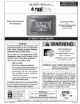
INSTALLATION & OWNER’S MANUAL ELECTRONIC PILOT KIT • INTERMITTENT SPARK IGNITION PILO T Models # EPK-2V(P) EPK-3V(P) • REMOTE OR MANUAL OPERATION • BATTERY OPERATION 2V model shown • VARIABLE FLAME HEIGHT CONTROL (Suitable for G4 and G45 series burners) EPK-2V/3V PILOT KITS Important: Read these instructions carefully before starting installation of the burner control system. WARNING If the information in this manual is not followed exactly, a fire or explosion may result, causing property damage, personal injury, or loss of life. The Peterson Real-Fyre® burner system is to be installed only in a solid-fuel-burning fireplace with a working flue constructed of noncombustible material. Solid fuels shall not be burned in a fireplace where the unit is installed. The installation, including provisions for combustion, ventilation air, and required minimum permanent vent opening, must conform with the National Fuel Gas Code (ANSI Z223.1/NFPA 54) and applicable local building codes. In Canada, the installation must conform with the Natural Gas and Propane Storage and Handling Installation Code (CSA-B-149.1). A damper stop clamp is included to maintain the minimum permanent vent opening and to prevent full closure of the damper blade. The chimney damper must be fixed fully opened when burning the unit. The burner system is designed to burn with yellow flames; thus, adequate ventilation is absolutely necessary. Do not store or use gasoline or other flammable vapors and liquids in the vicinity of this or any other appliance. WHAT TO DO IF YOU SMELL GAS: • Open a window. • Do not try to light any appliance. • Do not touch any electrical switch; do not use any phone in the building. • Immediately call the gas supplier from a neighbor’s phone and follow the gas supplier’s instructions. • If you cannot reach the gas supplier, call the fire department. Installation and service must be performed by an NFI Certified or other qualified professional installer, service agency, or the gas supplier. INSTALLER & CONSUMER These instructions MUST be retained with this appliance Robert H. Peterson Co. • 14724 East Proctor Avenue • City of Industry, California 91746 Rev 1 - 1306140730 1 L-A2-352 INSTALLATION & MODE D'EMPLOI KIT PILOTE ELECTRONIQUE • PILOTE D'ALLUMAGE INTERMITTENT SPARK Modèles # EPK-2V(P) EPK-3V(P) • FONCTIONNEMENT À DISTANCE OU MANUEL 2V modèle présenté • FONCTIONNEMENT SUR BATTERIE • FLAMME VARIABLE CONTRÔLE DE HAUTEUR (Convient pour les G4 et G45 brûleurs de la série) EPK-2V/3V KITS DE PILOTES AVERTISSEMENT Important: Lire attentivement ces instructions avant de commencer l'installation du système de contrôle du brûleur. Si les informations contenues dans ce manuel ne sont pas suivies à la lettre, un incendie ou une explosion pourraient s'ensuivre, causant des dommages matériels, des blessures ou des pertes de vie. La Peterson réel Fyre système de brûleur® doit être installé uniquement dans un foyer à combustible solide qui brûle avec une cheminée de travail construite en matériaux incombustibles. Les combustibles solides ne doit pas être brûlé dans un foyer où l'appareil est installé. L'installation, y compris les dispositions pour la combustion, l'air de ventilation et d'aération minimale requise ouverture permanente, doivent être conformes au Code national du gaz combustible (ANSI Z223.1/NFPA 54) et aux codes du bâtiment locaux. Au Canada, l'installation doit être conforme avec le stockage de gaz naturel et propane et le code d'installation de manutention (CSA B-149.1). Un collier d'arrêt d'amortissement est inclus pour maintenir l'ouverture de ventilation minimum permanent et pour empêcher la fermeture complète du clapet. Le registre de cheminée doit être fixé complètement ouvert lors de la combustion de l'appareil. Le système de brûleur est conçu pour brûler avec des flammes jaunes; ainsi, une ventilation adéquate est absolument nécessaire. Ne pas entreposer ni utiliser d'essence ou d'autres vapeurs et liquides inflammables à proximité de cet appareil ou de tout autre. QUE FAIRE SI UNE ODEUR DE GAZ: • Ouvrez une fenêtre. • Ne pas tenter d'allumer d'appareil. • Ne touchez à aucun interr upteur électrique; n'utilisez aucun téléphone dans le bâtiment. • Appeler immédiatement le fournisseur de gaz à partir du téléphone d'un voisin et suivez les instructions du fournisseur de gaz. Installation et l'entretien doivent être effectués par une personne certifiée NFI ou un autre installateur professionnel qualifié, une agence de service ou le fournisseur de gaz. INSTALLATEUR ET DE CONSOMMATION Ces instructions doivent être conservées avec l'appareil Robert H. Peterson Co. • 14724 East Proctor Avenue • City of Industry, California 91746 Rev 1 - 1306140730 2 L-A2-352 TABLE OF CONTENTS 3 4 5 5 6 7 8 8 8 8 8 9 9 9 10 10 10 10 10 11 11 13 13 13 15 15 15 15 15 15 17 17 18 19 20 TABLE OF CONTENTS IMPORTANT INFORMATION WIRING DIAGRAM SPECIFICATIONS REPLACEMENT PARTS LIST - 2V MODEL REPLACEMENT PARTS LIST - 3V MODEL INSTALLATION PREPARATION INSTALL PILOT MOUNTING BRACKET INSTALL THE VALVE INSTALL THE FLAME DIVERTER BRACKET INSTALL THE PILOT/IGNITER ASSEMBLY TO THE BURNER CONNECT TO THE GAS SUPPLY LEAK TEST INSTALL/REPLACE REMOTE TRANSMITTER BATTERY INSTALL/REPLACE SWITCH BOX BATTERIES HEAT SHIELD PLACEMENT SWITCH BOX PLACEMENT DECORATIVE MEDIA REPLACEMENT LIGHTING INSTRUCTIONS REMOTE LIGHTING MANUAL LIGHTING PILOT APPEARANCE SHUTTING DOWN REMOTE OPERATING INSTRUCTIONS ORIENTATION FLAME HEIGHT TIMER THERMOSTAT TEMPERATURE INDICATOR ( ˚F OR ˚C) TROUBLESHOOTING SYNCING THE REMOTE NOTES PAGE ELECTRONIC PILOT TROUBLESHOOTING (02V ONLY) WARRANTY Rev 1 - 1306140730 3 L-A2-352 IMPORTANT INFORMATION CHECK TO BE SURE THAT THE PROPER FUEL GAS IS BEING USED WITH THIS PILOT KIT. The installation, including provisions for combustion and ventilation air, must conform with local codes, or in the absence of local codes, with the National Fuel Gas Code (ANSI Z223.1/NFPA 54). This component and its individual shutoff valve must be disconnected from the gas-supply piping system when testing at pressures that exceed 1/2 psig. This is accomplished by closing the gas-supply line valve. This component must be isolated from the gas-supply piping system by closing its individual manual shutoff valve during any testing of the gas-supply system at test pressures up to and including 1/2 psig. A fireplace screen must be in place when the gas burner system is in operation. Unless other provisions for combustion air are provided, the screen shall have an opening(s) for introduction of combustion air. WHEN GLASS FIREPLACE ENCLOSURES (DOORS) ARE USED, OPERATE THE BURNER SYSTEM WITH THE GLASS DOORS FULLY OPEN; BOTH SIDES IF THE FIREPLACE IS A SEE-THROUGH TYPE. This appliance may be installed in an aftermarket, permanently located, manufactured (mobile) home where not prohibited by local codes. Installation of appliances designed for manufactured homes or mobile homes must conform with Manufactured Home Construction and Safety Standard, Title 24 CFR, Part 3280 in the U.S.; or with CAN/CSA Z240 MH in Canada; or with ANSI/NCSBCS A225.1/NFPA 501A, Manufactured Home Installations Standard when such as standard is not applicable. Do not use this appliance if any part has been underwater. Immediately call a qualified service technician to inspect the appliance and to replace any part of the control system and any gas control that has been underwater. Rev 1 - 1306140730 4 L-A2-352 WIRING DIAGRAM EPK-2V Wiring Diagram EPK-3V Wiring Diagram Pilot/Igniter assembly Ignition module pack Pilot/Igniter assembly Ignition module pack Wire harness Wire harness Shut off valve D-cell Batteries (4) D-cell Batteries (4) Control valve Control valve Switch Battery pack Switch Battery pack Fig. 5-1 SPECIFICATIONS Minimum firebox dimensions required for burner system (with EPK valve attached): Min. Firebox Dimensions Burner size Center Width * Depth Height EPK-2V EPK-3V 16/19" 31" 39" 16" 18" 18/20" 32" 40" 16" 18" 24" 36" 44" 16" 18" 30" 42" 50" 16" 18" 36" 48" 56" 16" 18" 42" 54" 62" 16" 18" 48" 60" 68" 16" 18" 54" 66" 74" 16" 18" 60" 72" 80" 16" 18" Model Maximum BTUs EPK-2V(P) 100,000 EPK-3V(P) 200,000 Table 2 - BTUs Center width Depth * This required width allows for centering of the log set. Table 1 - Minimum Firebox Dimensions Rev 1 - 1306140730 5 L-A2-352 REPLACEMENT PARTS LIST - 2V MODEL DO NOT REMOVE THE PILOT/IGNITER ASSEMBLY FROM THE VALVE OR IGNITER PACK. 5 1 9 ON ON 2 AUTO TEMP 3 FUNC OFF 4 7 8 6 Note: Photos not to scale Item Description Rev 1 - 1306140730 1. Pilot/igniter assembly (natural) or Pilot/igniter assembly (propane) 2. Pilot mounting bracket kit 3. Control valve (natural) or Control valve (propane) 4. Ignition module pack 5. Remote 6. Flame diverter bracket 7. Switch box (w/ switch, battery pack, and wire harness) 8. Main wire harness 9. Heat shield 6 L-A2-352 REPLACEMENT PARTS LIST - 3V MODEL DO NOT REMOVE THE PILOT/IGNITER ASSEMBLY FROM THE VALVE OR IGNITER PACK. 5 ON ON AUTO TEMP 1 FUNC OFF 9 2 8 4 7 3 6 Note: Photos not to scale Item Description Rev 1 - 1306140730 1. Pilot/igniter assembly (natural) or Pilot/igniter assembly (propane) 2. Pilot mounting bracket kit 3. Control valve (natural) or Control valve (propane) 4. Ignition module pack 5. Remote 6. Flame diverter bracket 7. Switch box (w/ switch, battery pack, and wire harness) 8. Main wire harness 9. Heat shield 7 L-A2-352 INSTALLATION This safety pilot system must be installed by a qualified professional service technician. Instructions must be followed carefully when installing to ensure proper performance and full benefit from the burner system and safety pilot system. These instructions must be used as a supplement to the instructions supplied with the Peterson burner system. Follow the burner system instructions and make adjustments as appropriate for the addition of a safety pilot system. Use gas pipe sealing compound that is resistant to all gasses (or Teflon tape) and apply to all male pipe connections. Make sure that all connections are tight. INSTALLATION The valve system is shipped pre-assembled for easy installation onto the burner pan. Fasten bracket to burner pan Note: Installation is easier when done outside of the fireplace. PREPARATION If the burner that the valve system is to be added to is already installed; remove all decorative media, set aside to be reinstalled later, and disconnect the flex connector from the burner pan (using the instructions that came with the original burner). Fig. 8-1 INSTALL PILOT MOUNTING BRACKET The pilot assembly comes with an L-shaped mounting bracket. Remove the two phillips screws holding the bracket in place, then use them to fasten the bracket to burner pan (short side toward the back of the pan) using the pre-drilled holes in the pan (see Fig. 8-1). Install for 2V and 3V valves is the same. 2V SHOWN. Attach the valve to the air mixer/fuel injector by rotating the burner pan. Fuel injector or air mixer INSTALL THE VALVE 1. Apply gas pipe sealing compound (or Teflon tape) to the male end of the fuel injector or air mixer on the burner. 2. Attach the adapter (pre-assembled to valve) to the fuel injector or air mixer by screwing the pan onto the adapter (Fig. 8-2). Take care not to damage the attached pilot assembly when rotating the burner pan. Be sure all connections are tight. Burner pan Adapter Important: The rear of the valve may need to be angled slightly upward to allow for the pan to sit flat against the fireplace floor. Adjust as necessary. Valve Fig. 8-2 INSTALL THE FLAME DIVERTER BRACKET For installation on G4/G45 burners only.When properly installed onto the burner pan, the flame diverter bracket will promote quicker ignition and protect the safety control system from overheating. Note: You must first install the flame diverter bracket before installing the pilot/igniter assembly. Use only the pilot/ igniter assembly pre-assembled with this kit. Never substitute with an existing pilot. 1. Place the flame diverter bracket over the side edge of the burner pan, near the location the safety control system pilot bracket will be attached. It should be placed approximately 2-1/2" from the rear wall of the burner pan (see Fig. 8-3). Rev 1 - 1306140730 8 REAR WALL 1 22-1/2 /2" BURNER Burner PAN pan FLAME Flame DIVERTER BRACKET diverter bracket Fig. 8-3 L-A2-352 INSTALLATION (Cont.) 2. Tap the bracket lightly with a hammer to secure it in place. Pilot assembly installed INSTALL THE PILOT/IGNITER ASSEMBLY TO THE BURNER CAUTION: Do not kink or damage the pilot supply tube, sparking, and sensor probes. Do not unscrew the gas line from the valve. 1. Using the two (2) remaining screws, mount the pilot assembly onto the bracket (from below) and tighten until snug (Fig. 9-1). Check to be certain the pilot hood and probes are situated above the edge of the pan. Adjust if necessary. 2. The valve is shipped with the pilot supply tube bent in an ideal manner to prevent damage / unsafe operation, and to allow for proper heat shield placement. Maintain this orientation at all times (reference Fig. 9-2 or 9-3). Fasten pilot assembly to bracket (Valve not shown for clarity) Fig. 9-1 Attach the flex connector to the elbow on the valve (rear view of valve) WARNING: Keep the pilot/igniter assembly clear at all times. Never cover any part of the pilot/igniter assembly. CONNECT TO THE GAS SUPPLY To connect the valve to the gas supply, the flex connector kit and component parts will be needed, which are included with the burner system. Refer to the PARTS LIST in the instructions supplied with the burner to identify the key parts needed. Fig. 9-2 2V models: Attach flex to valve 1. Be sure gas to the fireplace is off. Apply gas pipe sealing compound (or Teflon tape) to the male end of the gas stub. Attach the adapter from the flex connector kit to the gas-supply stub in the fireplace. 2. Attach the flex connector to the elbow/adapter on the control valve (see Fig. 9-2 or Fig. 9-3). Use Teflon tape or pipe compound.Tighten securely. (Discard the smaller connector adapter from the connector kit, as this is not needed.) 3. Connect the flex connector to the adapter on the gas stub. Tighten both ends securely. Attach the flex connector to the adapter on the valve Fig. 9-3 3V models: Attach flex to valve 4. Follow the instructions supplied with the Peterson burner system for proper burner placement. Note: The burner should be centered in the fireplace. LEAK TEST Turn on the fireplace gas supply, and test at all connections for leaks using the appropriate soapy water solution. If bubbles appear, a leak is present. Turn off the gas and tighten at all connections. Repeat until no leaks are present. If a leak persists, turn off the gas supply and contact the local gas company or dealer. NEVER USE A FLAME TO CHECK FOR LEAKS. Rev 1 - 1306140730 9 L-A2-352 INSTALLATION (Cont.) INSTALL/REPLACE REMOTE TRANSMITTER BATTERY CAUTION: ENSURE THE UNIT IS CONNECTED TO THE GAS LINE AND HAS BEEN TESTED FOR LEAKS BEFORE YOU INSERT BATTERIES. To access the battery, slide open the lid found on the back of the remote transmitter. Replace the old batteries with 3 new "AAA" batteries. Re-secure the lid. INSTALL/REPLACE SWITCH BOX BATTERIES To access the batteries, locate the switch box and turn it over. Use a Phillips screwdriver to remove the screw found on the back of the switch box, then remove the battery compartment. Replace the old batteries with 4 new "D" batteries. (See Fig. 10-1.) When battery replacement is complete; properly place the switch box in the the fireplace as instructed in this manual. Important: Low/dead batteries will affect burner system operation. Replace batteries any time the burner will not turn on. "D" batteries Fig. 10-1 Valve heat shield in place Heat shield Burner pan Fig. 10-2 2V models: Place heat shield Valve heat shield in place Heat shield HEAT SHIELD PLACEMENT Cover the valve with the heat shield as shown in Fig. 10-2 or Fig. 10-3. The heat shield must remain in place over the valve at all times during operation. Keep the area above the heat shield clear of decorative media or any other object. Important: Ensure the pilot supply tube does not interfere with heat shield placement. For 2V models, the tube will come out of the rear and coil back to the pilot. For 3V models, the tube will come out of the left side of the heatshield and coil to the pilot. Burner pan Fig. 10-3 3V models: Place heat shield SWITCH BOX PLACEMENT (EPK-2V shown here) Burner pan (G45 burner shown) Pilot wire bundle SWITCH BOX PLACEMENT Place the switch box outside of the firebox and a minimum of 6" from the burner/flame. If the switch box is in the firebox, the switch box must only be oriented as shown in Fig. 10-4. The switch box must not be placed in the rear of the fireplace, or in any other manner than shown in Fig. 10-4. Set the box on its side and place the bottom of the box toward the right firebox wall (box must be a minimum of 6" from the burner/flame). Be sure that the pilot and valve wire bundles remain clear of the burner, valve, and heat shield at all times. (FIREBOX) Valve and heat shield Wire bundles go around the valve and away from the burner. 6" min Valve wire bundle Switch box IF SWITCH BOX IS INSIDE FIREBOX; ORIENT ONLY AS SHOWN BELOW: (FIREBOX) DECORATIVE MEDIA REPLACEMENT Refer to the burner instructions for proper replacement of decorative media. Rev 1 - 1306140730 6" min 10 Bottom CAUTION: THE SWITCH BOX MAY BE HOT DURING AND AFTER OPERATION. BOX ON ITS SIDE Fig. 10-4 Place switch box L-A2-352 LIGHTING INSTRUCTIONS FOR YOUR SAFETY READ BEFORE LIGHTING WARNING: If you do not follow these instructions exactly, a fire or explosion may result causing property damage, personal injury or loss of life. A. This appliance is equipped with an ignition device that automatically lights the pilot. DO NOT attempt to light the pilot by hand. B. BEFORE OPERATING, smell all around the appliance area for gas. Be sure to smell next to the floor because some gas is heavier than air and will settle on the floor. WHAT TO DO IF YOU SMELL GAS • Do not light any appliance. • Do not touch any electric switch; do not use any phone in your building. • Immediately call your gas supplier from a neighbor's phone. Follow the gas supplier's instructions. If you cannot reach your gas supplier, call the fire department. C. Use only the supplied standing pilot toggle switch or the control/remote system components to light the pilot. This valve will not operate if the pilot is not lit and stable. D. Do not use this appliance if any part has been under water. Immediately call a qualified service technician to inspect the appliance and to replace any part of the control system and any gas control which has been under water. Attempted operation may result in fire or explosion resulting in property damage, personal injury or loss of life. REMOTE LIGHTING CAUTION: DO NOT attempt to light the pilot by hand. Note: Step 1 may not be required if previously done during an earlier lighting. ON II O I 1. Locate the 3-position switch on the switch box (see Fig. 11-1). Press the switch to the REMOTE position. 2. Locate the remote transmitter and press the ON button (see Fig. 11-2). The ignition sequence will begin. The remote receiver will emit an audible "beep"; then the igniter will begin to spark. After the pilot lights and is established, the valve will automatically open and the burner will light. Adjust to the desired setting(s) with the remote transmitter. See the REMOTE OPERATING INSTRUCTIONS section for details. Note: The ignition sequence will take approximately 5 seconds. WARNING: If the pilot fails to light within 10 seconds, press the OFF button on the remote transmitter or move the switch to the OFF position to turn OFF the system. Allow five (5) minutes for any gas in the unit to dissipate, then repeat step 2 above. IF YOU SMELL GAS, SEE STEP B ABOVE. If the pilot fails to light after several tries, turn all control/ remote system components to OFF and contact a qualified professional service technician. OFF REMOTE Fig. 11-1 Switch box, switch detail (Display screen) ON/UP key ON ON Temp. key AUTO TEMP FUNC OFF Function key OFF/DOWN key Fig. 11-2 Remote transmitter detail 11 INSTRUCTIONS D'ALLUMAGE POUR VOTRE SÉCURITÉ LISEZ AVANT D'ALLUMER AVERTISSEMENT: Si vous ne suivez pas ces instructions à la lettre, un incendie ou une explosion entraînant des dommages matériels, des blessures ou des pertes de vie. A. Cet appareil est équipé d'un dispositif d'allumage qui allume automatiquement la veilleuse. NE PAS essayer d'allumer la veilleuse manuellement. B. AVANT D'UTILISER, Sentez tout autour de l'appareil pour le gaz. Assurez-vous de sentir près du plancher, car certains gaz sont plus lourds que l'air et se déposent sur le sol. QUE FAIRE SI UNE ODEUR DE GAZ • Ne pas allumer l'appareil. • Ne touchez à aucun interrupteur électrique; n'utilisez aucun téléphone dans votre bâtiment. • Appelez immédiatement votre fournisseur de gaz à partir du téléphone d'un voisin. Suivez les instructions du fournisseur de gaz. Si vous ne pouvez joindre votre fournisseur de gaz, appeler les pompiers. C. Utilisez uniquement le commutateur à bascule fourni veilleuse permanente ou la commande / composants du système à distance pour allumer la veilleuse. Cette vanne ne fonctionne pas si le pilote n'est pas allumé et stable. D. Ne pas utiliser cet appareil si une partie quelconque a été submergée. Appelez immédiatement un technicien de service qualifié pour inspecter l'appareil et pour remplacer toute pièce du système de contrôle et toute commande de gaz qui a été sous l'eau. Tentative d'opération peut entraîner un incendie ou une explosion entraînant des dommages matériels, des blessures ou des pertes de vie. DISTANCE DE L'ÉCLAIRAGE ATTENTION: NE PAS essayer d'allumer la veilleuse manuellement. Note: Step 1 may not be required if previously done during an earlier lighting. SUR II O I 1. Localisez le commutateur à 3 positions sur le boîtier de commande (voir Fig. 12-1). Appuyez sur l'interrupteur à la position REMOTE. OFF 2. Localisez la télécommande et appuyez sur le bouton ON (voir Fig. 12-2). La séquence d'allumage commencera. Le récepteur de la télécommande émettra un "bip" sonore, puis l'allumeur commence à susciter. Après les veilleuses et est établie, la vanne s'ouvre automatiquement et le brûleur s'allume. Choisissez le réglage souhaité (s) avec la télécommande. Voir la section INSTRUCTIONS DE FONCTIONNEMENT A DISTANCE pour plus de détails. Note: La séquence d'allumage dure environ 5 secondes. AVERTISSEMENT: Si le pilote ne s'allume pas dans les 10 secondes, appuyez sur le bouton OFF de la télécommande ou déplacez l'interrupteur à la position OFF pour éteindre le système. Attendez cinq (5) minutes pour n'impor te quel gaz dans l'unité à se dissiper, puis répétez l'étape 2 ci-dessus. S'IL YA UNE ODEUR DE GAZ, voir l'étape B CI-DESSUS. Si le pilote ne s'allume pas après plusieurs essais, tournez tout contrôle / composants du système à distance sur OFF et contactez un technicien qualifié. 12 DISTANCE Fig. 12-1 Boîte de contrôle, détail interrupteur (Écran d'affichage) Touche SUR/UP ON ON AUTO TEMP Touche Température FUNC OFF Touche Fonction Touche OFF/BAS Fig. 12-2 Détail télécommande LIGHTING INSTRUCTIONS (cont.) MANUAL LIGHTING CAUTION: DO NOT attempt to light the pilot by hand. 1. Locate the 3-position switch on the switch box (see Fig. 13-1). Press the switch to the ON position. II O I The remote receiver will emit an audible "beep"; then the igniter will begin to spark. After the pilot lights and is established, the valve will automatically open and the burner will light. ON OFF REMOTE Note: The ignition sequence will take approximately 5 seconds. WARNING: If the pilot fails to light within 10 seconds, turn OFF the system. Allow five (5) minutes for any gas in the unit to dissipate, then repeat step 2 above. IF YOU SMELL GAS, SEE STEP B ABOVE. Fig. 13-1 Switch box, switch detail If the pilot fails to light after several tries, turn the system OFF and contact a qualified professional service technician. Note: In manual mode, the remote transmitter will not operate the burner system. PILOT APPEARANCE Periodically check the pilot for proper flame pattern. The pilot flame should encircle the generator tip, and is preset at the factory (see Fig. 13-2). If the pilot flame burns incorrectly; shut down completely and contact a qualified professional service technician. SHUTTING DOWN • For a remote shut down, press the OFF button on the remote transmitter. • For a manual shutdown (or if your remote is lost), press the switch on the switch box to the OFF position. 13 Fig. 13-2 Proper pilot flame INSTRUCTIONS D'ALLUMAGE (cont.) ALLUMAGE MANUEL ATTENTION: NE PAS essayer d'allumer la veilleuse manuellement. Le récepteur de la télécommande émettra un "bip" sonore, puis l'allumeur commence à susciter. Après les veilleuses et est établie, la vanne s'ouvre automatiquement et le brûleur s'allume. Note: La séquence d'allumage dure environ 5 secondes. SUR II O I 1. Localisez le commutateur à 3 positions sur le boîtier de commande (voir Fig. 14-1). Appuyez sur l'interrupteur sur la position ON. OFF DISTANCE Fig. 14-1 Boîte de contrôle, détail interrupteur WARNING: Si le pilote ne s'allume pas dans les 10 secondes, éteignez le système. Attendez cinq (5) minutes pour n'importe quel gaz dans l'unité à se dissiper, puis répétez l'étape 2 ci-dessus. S'IL YA UNE ODEUR DE GAZ, voir l'étape B CI-DESSUS. Si le pilote ne s'allume pas après plusieurs essais, mettez le système hors tension et contactez un technicien qualifié. Note: En mode manuel, la télécommande ne fonctionne pas du système de brûleur. ASPECT PILOTE Vérifiez périodiquement le pilote pour le modèle de la flamme. La flamme de la veilleuse devrait encercler la pointe du générateur, et est préréglé en usine (voir Fig. 14-2). Si la flamme de la veilleuse brûle mal; complètement arrêté et contacter un technicien de service qualifié. ÉTEINDRE • Pour un arrêt à distance, appuyez sur le bouton OFF de la télécommande. • Pour un arrêt manuel (ou si votre télécommande est perdue), appuyez sur l'interrupteur sur le boîtier de commande à la position OFF. 14 Fig. 14-2 Une bonne flamme de la veilleuse REMOTE OPERATING INSTRUCTIONS ORIENTATION Prior to remote transmitter use, light the appliance per the REMOTE LIGHTING section. The remote will only operate the burner system in remote mode. Familiarize yourself with the transmitter keys and display, as illustrated in Fig. 15-1 and Fig. 15-2. (Display screen) ON/UP key Identify the four transmitter keys: ON ON • ON/OFF KEYS: These keys turn the system ON or OFF. Temp. key AUTO TEMP FUNC OFF • FUNCTION KEY: This key, when the system is on, will toggle between the selection of two modes: Flame Height and Timer. • TEMP KEY: This key, when the system is on, is used to set the desired temperature via the Thermostat mode. • UP/DOWN KEYS: In Flame Height, Timer, Or Thermostat mode, the ON/OFF keys become UP/DOWN keys to increase or decrease the Flame Height, Timer amount, or Set Point Temperature. The display will show all active icons on the screen. FLAME HEIGHT Five flame height levels are available. Press the Function key to index to the Flame Height mode. A number 1 - 5 will be displayed at the bottom of the screen. See Fig. 15-3 Pressing the Up/ Down keys once will increase/decrease the flame height by 1 of 5 increments. OFF/DOWN key Fig. 15-1 Remote transmitter detail ROOM 88°F Transmission Flame Height / Timer / Set Temp. detail TIMER SET 88°F Room temperature Flame icon indicates system is in operation Fig. 15-2 Remote display detail ROOM 80°F TIMER Set desired flame level 1-5 In Timer Mode, the unit will remain functioning until the set amount of time has expired. Press the Function key to index to the Timer mode. Pressing the Up/Down keys once in this mode will increase/decrease the set time in increments of 10 minutes. See Fig. 15-4. To turn off the timer mode press the OFF key. This will turn off the unit. Function key TIMER SET 73°F Fig. 15-3 Flame height detail ROOM THERMOSTAT 80°F In Thermostat Mode, the unit will remain functioning until the room temperature increases 4°F above the Set Point Temperature. It will turn back on at 4°F below the Set Point Temperature. Press the Temp key so the Set Temperature is displayed (bottom of screen). See Fig. 15-5. Pressing the Up/Down keys once in this mode will increase/decrease the set temperature. Note that the temperature display on the top of the screen is the room temperature according to the remote transmitter. Set desired time TIMER SET Fig. 15-4 Timer detail Note: The system remains in operation while the remote is in Thermostat Mode, and the flame will only turn on and off according to the set temperature. The unit cannot be manually turned on or off unless the Thermostat Mode is exited via the Temp button. 20°e ROOM 80°F Set desired temperature TEMPERATURE INDICATOR ( ˚F or ˚C) The temperature can be displayed in °F or °C. When you first install the batteries, the temp indicator at the top of the screen will be flashing. Use the Up/Down keys to switch between °F or °C. 15 Room temperature TIMER SET 75°F Flame icon indicates system is in operation Fig. 15-5 Thermostat detail MODE D'EMPLOI À DISTANCE ORIENTATION Avant la première utilisation télécommande, allumez l'appareil pour la section d'éclairage à distance. La télécommande ne fonctionne le système de brûleur en mode distant. Familiarisez-vous avec les touches de l'émetteur et de l'affichage, comme illustré dans la Fig. 16-1 Et Fig. 16-2. (Écran d'affichage) Touche SUR/UP Identifier les touches de l'émetteur quatre: ON ON • SUR/OFF TOUCHES: Ces touches tourner le système sur SUR ou OFF. • TOUCHE FONCTION: Cette touche, lorsque le système est activé, permet de basculer entre la sélection de deux modes: Hauteur de flamme et de la minuterie. • TOUCHE TEMPERATURE: Cette touche, lorsque le système est activé, est utilisé pour régler la température désirée via le mode thermostat. • UP/BAS TOUCHES: Dans la hauteur des flammes, Minuteur, Thermostat Ou le mode, la touche ON / OFF touches deviennent touches HAUT / BAS pour augmenter ou diminuer la hauteur de la flamme, le montant minuterie, ou la température de point de consigne. L'écran affichera toutes les icônes actives sur l'écran. HAUTEUR DE LA FLAMME Cinq niveaux de hauteur de flamme sont disponibles. Appuyez sur la touche de fonction à l'index en mode hauteur de la flamme. Un certain nombre de 1 à 5 apparaît au bas de l'écran. Voir Fig. 16-3 Clés les touches Haut / Bas fois pour augmenter/diminuer la hauteur de la flamme par 1 de 5 incréments. AUTO TEMP FUNC OFF Touche Température Touche OFF/BAS Fig. 16-1 Détail télécommande ROOM 88°F Transmission Hauteur flamme / Minuteur / RéglezTemp. détail TIMER SET 88°F Icône indique que le système en fonctionnement ROOM 80°F Réglez la hauteur de flamme désirée de 1 à 5 En mode chronomètre, l'unité restera jusqu'à ce que le fonctionnement montant fixé de temps a expiré. Appuyez sur la touche de fonction à l'index de la mode minuterie. En appuyant sur les touches Haut / Bas fois dans ce mode pour augmenter / diminuer l'heure réglée par incréments de 10 minutes. Voir Fig. 16-4. TIMER SET 73°F Fig. 16-3 Détail hauteur de la flamme ROOM THERMOSTAT En mode thermostat, l'unité restera fonctionne jusqu'à ce que la température ambiante augmente de 4°F au dessus de la température de consigne. Il se remettra en marche à 4°F en dessous de la température de consigne. Appuyez sur la touche Temp de sorte que la température de consigne est affichée (en bas de l'écran). Voir Fig. 16-5. En appuyant sur les touches Haut/Bas fois dans ce mode pour augmenter/diminuer la température de consigne. Notons que l'affichage de la température en haut de l'écran est la température ambiante en fonction de la télécommande. Note: La température ambiante Fig. 16-2 Détail d'affichage à distance MINUTEUR Pour désactiver le mode de minuterie appuyez sur la touche OFF. Cela permettra d'éteindre l'appareil. Touche Fonction 80°F Régler l'heure désirée TIMER SET Fig. 16-4 Détail minuterie Le système continue de fonctionner alors que la télécommande est en mode thermostat, et la flamme ne s'allume et s'éteint en fonction de la température de consigne. L'appareil ne peut être manuellement activé ou désactivé à moins que le mode thermostat est sorti via le bouton Temp. 20°e ROOM 80°F Régler la température désirée TEMPERATURE INDICATOR ( ˚F or ˚C) La température peut être affichée en °F ou °C. Lorsque vous installez les piles, l'indicateur de température dans la partie supérieure de l'écran se met à clignoter. Utilisez les touches Haut / Bas pour basculer entre °F ou °C. 16 TIMER SET 75°F La température ambiante L'icône de flamme indique que le système est en fonctionnement Fig. 16-5 Thermostat détail TROUBLESHOOTING PROBLEM 1. Pilot will not light CAUSE SOLUTION a. Obstruction in pilot gas supply or pilot gas-supply line is kinked a. Clear out obstruction. Replace pilot gassupply line if kinked b. Inadequate gas supply b. Have gas pressure checked by installer or gas supplier c. Air in line d. Gas is shut off on control valve (3V models only) 2. No spark at pilot 3. Pilot lights, but main burner will not 4. Log set not burning properly c. Air should clear; attempt to relight d. Turn on valve (3V models only) a. Loose wires a. Check all wires are securely in place b. Dead batteries b. Replace batteries c. Fa u l t y sw i t c h o r r e m o t e ( i f equipped) c. Replace the switch box unit or remote system as appropriate a. Loose or broken connector wires a. Check and replace if necessary b. Batteries too low for voltage output b. Replace with new ones c. Defective valve c. Replace valve a. Low flame/uneven flame a. Check for low gas pressure; should have operating pressures of 7" w.c. for natural gas, 11" w.c. for propane at manifold b. Burner should be filled completely with sand or vermiculite 5. Log set shuts down during operation a. Glass doors closed, causing excessive heat buildup b. Pilot electrode not properly set to pilot location a. Open glass doors b. See INSTALL THE PILOT ASSEMBLY TO THE BURNER section c. Heat shield not in place c. Place heat shield over valve. Be sure the solid black face of the shield is between the valve and the burner 6. Intermittent ignitor spark during use (main burner has been burning for well over a minute). a. Embers or sand covering pilot assembly a. Clear all foreign material from around the pilot assembly 7. Remote control not functioning a. Low/dead batteries a. Check and replace b. No gas flow to the valve b. Check gas supply to valve c. Remote too far from receiver c. Move remote closer to receiver d. Spark ignition interfering with remote signal d. Move remote closer to receiver Periodically inspect the pilot assembly and valve controls and maintain them free of obstruction or debris. If the pilot flame is not blue with possibly yellow tips and does not impinge on the electrodes or if the pilot does not stay lit, contact a qualified professional service technician to service the pilot system. SYNCING THE REMOTE The ignition module pack has a pinhole sync button located next to the LED light (see Fig. 17-1). Simultaneously press the sync button with a paperclip or similar object and the "ON" button on the remote. SYNC button LED light Fig. 17-1 17 The codes below are a guide if the ignition module pack is flashing the red LED lights: RED LED TROUBLE CODES 1 Flash Nat/LP selector not in correct position 2 Flashes HI voltage coil failure, no spark 3 Flashes Shorted sensor, no gas flow, no ignition of pilot in 60 seconds NOTES PAGE Please use this page to record any information that you may want to have at hand. 18 ELECTRONIC PILOT TROUBLESHOOTING (02V ONLY) Detail A Electrode (A) When adjusting the spark electrode (if necessary); NEVER adjust the electrode by bending the wire. ALWAYS adjust the electrode by loosening the retainer nut(s), then adjust accordingly. The minimum gap between the spark electrode/ sensor electrode and the pilot flame hood is 1/8". The maximum is 5/32". Hood Spark electrode Electrode Ceramic Threaded barrel 1/8" min. gap Sensor electrode 1/8" min. gap Fig. A-1 If the electrode ceramic is loose in the threaded barrel; the pilot assembly must be replaced. Retainer nuts Detail B Terminal Connections (B) All of the connections on the control module must be properly attached. If the spade terminals are loose; inspect to ensure they correctly appear as detailed below. Use needle nose pliers to clamp down on the center/sides of the terminals if needed (to provide a tight fit.) Detail C (Fig. C-1) Spade Terminal Detail (Fig. B-1) CORRECT INCORRECT Ensure that spade terminals (S and I) are attached securely Ensure that multi-wire connector is properly locked in place Control Module (DESIGN MAY VARY) DO NOT bundle tightly together as shown (Fig. B-2) Tighten terminals if needed Assembly Wires (C) DO NOT bundle the excess pilot assembly wires tightly together as this can reduce the intensity of the spark. (Fig. B-3) 19 WARRANTY PETERSON VENTED DECORATIVE GAS APPLIANCE LIMITED WARRANTY All Peterson gas logs are WARRANTED for as long as you own them (lifetime). All Peterson burner assemblies are WARRANTED for TEN (10) YEARS. All Peterson glass is WARRANTED for FIVE (5) YEARS. SPK-26 controls are covered by a THREE (3) YEAR “All Parts” Warranty. APK-17 controls are covered by a TWO (2) YEAR “All Parts” Warranty. All other Peterson valves, pilots, and controls are covered by a ONE (1) YEAR Limited Warranty (excluding batteries). PLEASE KEEP A COPY OF YOUR SALES SLIP FOR PROOF OF PURCHASE This warranty applies to the original purchaser and to single family residential use only. It commences from date of purchase, and is valid only with proof of purchase. This warranty does not cover parts becoming defective through misuse, accidental damage, electrical damage, improper handling, lack of routine maintenance, storage, and/or installation. Product must be installed (and gas must be connected) as specified in the instructions or operator’s manual, by a qualified professional installer. Accessories, parts, valves, remotes, etc., when used must be Peterson Co. product. This warranty does not apply to rust, corrosion, oxidation, or discoloration, unless the affected component becomes inoperable. It does not cover labor or labor-related charges. This warranty specifically excludes liability for indirect, incidental, or consequential damages. Some states do not allow the exclusion or limitation of incidental or consequential damages, so the above exclusion may not apply to you. This warranty gives you specified legal rights, and you may have other rights that may vary from state to state. For additional information regarding this warranty, or to place a warranty claim, contact the R.H. Peterson dealer where the product was purchased. TO REGISTER YOUR PRODUCT ONLINE GO TO: WWW.RHPETERSON.COM, AND CLICK ON PRODUCT REGISTRATION. THANK YOU FOR YOUR PURCHASE. Quality Check Date:_________________ Leak Test: ________________ Burn Test: _________________ Gas Type: Inspector: ________________ Robert H. Peterson Co. • 14724 East Proctor Avenue • City of Industry, CA 91746 20 Nat. / L.P.