1
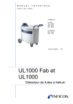
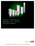
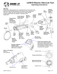
27/08/2013
F0932
1
AIMANT PERMANENT DE LEVAGE
EN NEODYMIUM
BUX.NEO
Un seul utilisateur peut lever et transporter des charges autorisées jusqu'à 2.000 kg.
On épargne ainsi beaucoup de temps comparé aux manœuvres nécessaires
avec des élingues et des câbles de levage.
Surface aimantée prismatique pour plats et ronds.
Exécution très compacte et de faible poids propre étant donné que ces porteurs sont munis
d' aimants les plus "costauds" en Neodymium (Nd Fe B).
Activation "On-Off" aisée par levier avec verrouillage empêchant
une éventuelle fausse manœuvre.
La capacité nominale de levage inclut un facteur de sécurité de min "x 3"
et est testée pour de l'acier St 37 propre de 50 mm d'épaisseur.
La capacité de levage peut varier en fonction de l'épaisseur
et de la qualité de surface des pièces à transporter.
force autorisée
plat (daN)
125
250
500
1.000
1.500
2.000
ép. pièce (mm) *
2... ≥ 25
4... ≥ 30
6... ≥ 40
10... ≥ 60
15... ≥ 80
15... ≥ 80
rond (daN)
40
125
250
500
750
1.000
pour Ø pièce (mm)
50...100
60...200
65...270
100...300
150...350
150...350
force testée (daN)
320
800
1.600
3.200
4.500
6.000
longueur (mm)
95
151
246
306
410
480
largeur (mm)
60
100
120
146
165
165
hauteur (mm)
110
168
168
216
161
251
largeur (mm) pôles
2 x 16
2 x 18
2 x 24
2 x 35
2 x 40
2 x 40
poids propre (kg)
3
10
18
36
68
85
Ref.
BUX.NEO.0125
BUX.NEO.0250
BUX.NEO.0500
BUX.NEO.1000
BUX.NEO.1500
BUX.NEO.2000
SUR DEMANDE :
Tous ces modèles pour une temperature jusqu' à 250 °C
27/08/2013
F0932
2
CHARGEUR VERTICAL
AVEC AIMANT DE LEVAGE
BUX.NEO.HV
Avec aimant de levage Ref. BUX.NEO.0250 ou 0500.
Permet le basculement de pièces plates à 90°, particulièrement intéressant
pour l'alimentation de machines à broche horizontale :
tous, centres d'usinage, aléseuses, etc…
L'aimant porteur peut coulisser en fonction de la largeur ou du diamètre des pièces sur un
longeron télescopique en acier amagnétique muni de deux butées.
L'anneau en bout est réglable en fonction du entre de a gravité de la charge.
Remarque :
Le chargeur (sans aimant) peut être monté par la suite sur un aimant déjà existant.
Les aimants (250 et 500 daN) ne sont pas interchangeables sur le même chargeur.
Sur demande : avec aimant de 1.000 daN
avec aimant Ref.
NEO.BUX.0250
NEO.BUX.0500
capacité pour plat (daN)
250
500
largeur charge (mm)
300 - 800
300 - 1000
longueur x largeur (mm)
958 X 210
1158 X 275
hauteur (mm)
255
255
poids propre (kg)
27
38
Ref.
NEO.HV.0250
NEO.HV.0500
centre de gravité de la pièce
adaptable au centre de gravité
27/08/2013
F0932
3
AIMANT PERMANENT DE LEVAGE
EN NEODYMIUM
APPLICATIONS :
Chargement –
déchargement d'une fraiseuse.
Pièces en fonte dans un centre d'usinage.
Cylindre massif.
Pièce lourde.
EXEMPLES D'EXÉCUTIONS SPÉCIALES :
Pôles allongés
pour disques de grand diamètre.
Avec œillet supplémentaire
sur le côté pour un levage vertical.
Pôles surélevés pour préhension
entre flasques ou poutres.
27/08/2013
F0932
4
AIMANT PERMANENT DE LEVAGE EN SM-CO
POUR TEMPERATURES JUSQU'A 300°C
SPD.SP.
E
G
F
D
E
Un seul utilisateur peut lever et transporter des charges autorisées jusqu'à 1.000 kg.
On épargne ainsi beaucoup de temps comparé aux manœuvres nécessaires avec
des élingues et des câbles de levage.
Surface aimantée prismatique pour plats et ronds.
Avec aimants en Samarium Cobalt permettant une utilisation
avec une température de max. de 300°C.
Activation "On-Off" aisée par levier avec verrouillage empêchant
une éventuelle fausse manœuvre.
La capacité nominale de levage inclut un facteur de sécurité de min "x 3" et est testée pour
de l'acier St 37 propre de 50 mm d'épaisseur.
La capacité de levage peut varier en fonction de l'épaisseur et de la qualité de surface des
pièces à transporter.
N
D
min mm
max/min max mm
kg A
B
C
D
E
F
G
H
I
L
M
N
O
G
er (kg)
50
10
30/120
2000
12 200 168 172 43 83
125
15
30/240
2000
16 243 218 193 43 102 66 112 266 15 95 63 54
67 110 242 10 95 60 35
250
15
30/270
2500
500
20
50/400
3000
26 287 260 190 60 65 98 132 280 17 125 80 50B
85 385 345 284 60 165 92 170 390 25 145 80
B
C
D
plat
rond
100
50
250
125
500
250
1.000
E
168 172 43 83
F
500
G
Charge (mm)
20
H
30 / 270
I
50 / 400
L
M
A
H
E100 F 50G
H 10I
2.500
287 260 190
60
250 125
15
83 67 110 242 10
500 250
15
102 66 112 266 15
1000 500
20
65 98 132 280 17
3.000
385 345 284
60
165
N
67 110 242 10 95 60 35
218 193 43 102 66 112 266 15 95 63 54
260 190 60 65 98 132 280 17 125 80 50
345 284 60 165 92 170 390 25 145 80
A
0
3
I
M
L
N
max/min max mm
min mm
B
C
D
SP15.00100
ép min. Ø min./max L. max.
SP15.00250
10
30 / 120
2.000 200 168 172 43
SP15.00500
15
30 / 240
2.000 243 218 193 43
SP15.01000
15
0
Power (kg)
Code
Capacité (kg)
F
M
L
I
C
H
92
170 390
25
kg A
Poids
2000Ref. 12
(kg)
30/240
2000
16
95 60 35
12
SPD.SP.0100
30/270
2500
26
95 63 54
16
SPD.SP.0250
50/400
3000
85
125 80 50
26
SPD.SP.0500
145
L
M
N
30/120
80
0
85
SPD.SP.1000
B
C
200 168 172
243 218 193
287 260 190
385 345 284
27/08/2013
DE
TH
F0932
DESIG
THIN P
5
AIMANT PERMANENT DE LEVAGE
POUR TOLES MINCES
EMS.TP
Les tôles minces n’acceptent pas le magnétisme des aimants de levage standards.
leur performance est nettement réduite.
plusieurs tôles sont prises à la fois.
la sécurité est réduite.
Ces 2 porteurs avec aimants permanents en Néodymium sont spécialement étudiés pour ce
OPERATING INSTRUCTIONS
problème de tôles minces avec les avantages suivants :
prise d’une seule tôle à la foisThelifterisintheOFFposition
à partir d’une pile.
la capacité est donnée pour différentes épaisseurs de tôles
la poignée de commande fonctionne comme un frein à main de voiture ;
le bouton à l’extrémité actionne un loqueteau de sûreté qui empêche le déclenchement
accidentel pendant le travail.
WhyThinPla
ToSwitchthelifterON
opération simple, rapide et sûre.
Rotate the handle 120˚ anti-clockwise.
Thin plate cannot a
Ensure the lever is securely locked in place
magnets.
before commencing with the lift.
Mode d’emploi :
Usingstandardlif
ThelifterisintheOFFposition
1. l’aimant est en position «OFF».
• Dramaticallyred
ThelifterisintheONposition
2. pour placer l’aimant en position
«ON», tourner le levier de commande de 120° dans
le
• Pickingupsheet
sens opposé des aiguilles d’une montre.
• Un-safelifts
3. s’assurer que le levier est bien verrouillé.
4. pour placer l’aimant en position «OFF» : déposer la charge sur le sol et tourner le levier de commande de 120° dans
le sens des aiguilles d’une montre.
ToSwitchthelifterOFF
Ultralift TP o
5. la charge est libre.
Return the load to the floor or support.
Depresstheplungeronthehandleandrotate
• Aliftingmagnet
ToSwitchthelifterON
120˚ clockwise to its stop position.
• SWLbasedonm
dimensions (mm)
poids
Ref.• Guaranteedliftin
(kg)
RotateA the handle
120˚
anti-clockwise.
B
C
D
E
F
Releasetheplungertocompletethe
• Simple,quickop
switchingprocess
150
202
126
74
181
8
EMS.TP.150
Ensure
the lever
is 100
securely
locked
in place
• Twosizesinthe
300
352
100
126
74
181
15
EMS.TP.300
be lifted using tw
OPERATING INSTRUCTIONS
1
2
Why
before commencing with the lift.
F
3
ThelifterisintheONposition
E
D
Thin p
magn
Using
SpreaderBea
• Dra
Eclipse Magnetics s
• liftsPic
ensure safe
are
alsoproduceequip
• Un
A
B
4
5
C
ToSwitchthelifterOFF
Modelde tôle
Self (daN) :
Dimensions (mm)
Capacité en fonction de l'épaisseur
No floor
Weight or support.
Return
the load toépaisseur
the
A
B
C
D
E
F
(mm) (kg)
Ref.
Depresstheplungeronthehandleandrotate
5 mm
6 mm TP150
8 8mm 150
10 mm100
202
126
74
181
TP300
15
300
352
100
126
74
181
75 kg
100 kg
kg
200 kg
EMS.TP.150
120˚ clockwise
to
its stop150position.
Material
Thickness
(mm)
Mate
Thick
(mm
SWL
SWL
5
(kg)
Ultr
Length
Max
(mm)
6
(kg)
• Al
100
150
2000
200
•
SW
150 kg
200 kg
300 kg
400 kg
EMS.TP.300
EclipseMagneticsL
Special Lifting and Automation
En règle générale la longueur max de tôle est de 1.500 mm pour la Ref. EMS.TP.150 etAtlas
de Way• Gu
Atlas North
2.000 mm EclipseMagneticsproduceafullrangeofpneumaticand
pour la Ref. EMS.TP.300. Pour de plus grandes longueurs, des traverses peuvent
Releasetheplungertocompletethe
electro-permanentmagneticliftingequipmentwhichis
Sheffield S4 7QQ
être livrée» ainsi qu’un dispositif permettant le basculement de la charge à 90°.
• Sim
designedspecificallyforspecialapplications.
England
switchingprocess
• Tw
www.eclipse-magnetics
be
F
75
1500
27/08/2013
F0932
6
AIMANT PERMANENT DE LEVAGE
A TRIPLE SECURITE
EMS.UL
Ces porteurs avec aimants permanents en Néodymium ont été spécialement étudiés pour
obtenir une manutention avec une sécurité maximum :
La poignée de commande fonctionne comme un frein à main de voiture (3)
En actionnant le bouton à l’extrémité du levier actionne un loqueteau de sûreté. En tournant
le levier de 120° dans le sens anti-horaire ce loqueteau vient se placer en dessous de l’ergot
de sûreté et empêche le déclenchement accidentel pendant le travail. L’aimant de levage
est ainsi sur la position «ON»; pour le mettre sur «OFF» réaliser l’opération inverse (1).
Pendant le levage et aussi longtemps que l’œillet de levage est sous tension, un mécanisme
breveté empêche le déclenchement de l’aimant (2). Ce n’est que lorsque le porteur est
revenu sur le sol qu’on peut facilement actionner le déclenchement de l’aimant à une seule
main, l’autre main restant libre pour enlever le crochet du palan.
Ce porteur est livré avec une cale de sécurité ou «safety shim» (4)
qui permet de pré-tester toutes les charges, indépendamment du poids, du type et de
l’épaisseur de la matière et de la qualité de surface de la charge.
Il suffit de placer cette cale entre le porteur et la charge.
Si le porteur accepte de lever la charge sur une courte distance le
coefficient de sécurité x 3 est garanti.
Safety Catch
Ceci est particulièrement intéressant si on doit soulever des charges très diverses
ou non répertoriées.
The safety catch l
Safety Catch
providing a robus
mechanism.
The safety catch locks the handle
dimensions (mm)
poids in the ‘on’ position,
Ref.
providing a robust and positive
lock
to
the
switching
(kg)
A
B
C
D
E
F
Lifting Eye
mechanism.
101
155
69
74
64
152
4
EMS.UL.0125
Additional safety
155
214
92
96
94
218
11
EMS.UL.0250
Lifting
Eye
with the load, the
224 FASTEST
300AND SAFEST
122 OPTION
128 FOR LIFTING*
123
266
27
EMS.UL.0500
magnet c
Additional
safety catch. Once the lifting eyethat
is inthe
tension
Safety •Catch
Safety
Catch
Lowerthemagnetontotheplate
260
359
176
174
140
391
63
EMS.UL.1000
(Patent
No. GB23
the‘on’
load,
thelocks
mechanism
locks
handle
ensuring
The safety
locks the handlewith
in the
position,
The
safety
catch
the handle
in the
the ‘on’
position,
• catch
Turnthehandle
368 • Liftinsafety
477
233
227the magnet
195 cannot
493 be released
157
EMS.UL.2000
FASTEST AND SAFEST OPTION FOR LIFTING*
that
by
accident.
providing a robust and positive lock
to theaswitching
providing
robust and positive lock to the switching
• Lowerthemagnetontotheplate
Hand Brake R
*on pre-tested or known loads
(Patent
No.
GB2399456)
mechanism.
mechanism.
• Turnthehandle
F
The magnet can b
• Liftinsafety
THE SA
THE SAFESTINLIFT
THE
IN THE WORLD
THE SAFEST
THELIFT
SAFEST LIFT
IN THE WORLD
IN THE WORLD
THE SAFEST LIFT
IN THE WORLD
Hand
Lifting Eye
LiftingBrake
Eye Release
Shim
F
E can be released easily, by usingSafety
magnet
one
hand.
Additional
safety catch. Once theThe
lifting
eye
is in tension
Additional
safety
catch. Once the lifting eye is
in tension
Safety Catch
*on pre-tested or known loads
The ensuring
Eclipse Magn
with
the load,
thelocks
mechanism
locks
handle
ensuring
with
the‘on’
load,
the
mechanism locks the handle
The safety
catch
the handle
in the
the
position,
Safety
Shim
magnetic
lifting m
AFEST OPTION FOR
LIFTING*
FASTEST
AND SAFEST OPTION FORE LIFTING*
that
the magnet
cannot
be released
accident.
that by
thethe
magnet
cannot be released by accident.
providing
a
robust
and
positive
lock
to
switching
D
agnetontotheplate
• Lowerthemagnetontotheplate(Patent No. GB2399456)
‘safety
shim’ (inte
The
Eclipse
Magnetics Ultralift Plus is the only
permanently
(Patent
No. GB2399456)
mechanism.
ndle
• Turnthehandle
testingwith
of the
magnetic lifting magnet to be supplied complete
a loa
y
• Liftinsafety
material
type,
D Hand Brake Release
‘safety shim’
(internationally
A
Hand
Brake
Release patented). This allows pre- ma
loads
*on pre-tested or known loads
Lifting Eye
If the
load passes
testing
of theone
load
toreleased
be lifted,
irrespective
weight,
F
F can be released
The
magnet
by
using
hand.
magnet
can
easily,
by usingofone
hand.
Cbe
Additional
safety catch.BOnceeasily,
theThe
lifting
eye
is
in
tension
material type, material thickness and surface condition.
A
Length
Flat Sec
with the load, the mechanism locks
the
handle
ensuring
IfWeight
the
load
passes
a Dimensions
3:1 safety
factor is guaranteed.
Shim
Shim
Model No. Safety
(mm)
Max
SWL
T
E Safety
B
C
AFEST OPTION FORE LIFTING*
that capacité
the magnetépaisseur
cannot
be released
by accident.
min.
capacité pour
Ø max pour longueur max
M
agnetontotheplate
Ref.
The
Eclipse
Magnetics
Ultralift
Plus
is
the
only
permanently
The
Eclipse
Magnetics
Ultralift
Plus
is
the
only
permanently
Length
Flat
Section
Round
Section
(kg)
(mm)
(kg)
(Patent
No.(kg)GB2399456)
pour plat
pour plat (mm)
rond (kg)
Arond (mm)
B
C (mm)D
E
F
ndle
magnetic
lifting (mm)
magnet
to be supplied
with69a toSWL
magnetic
lifting
magnet
be
supplied
complete
with 125
a
Model No.
Weight
Dimensions
Max4 complete
SWL 155
Thickness
Diameter
UL0125+
101
74
64
152
1500
125
20
50
200 Minimum 1.500
EMS.UL.0125
y
Maximum
D
D ‘safety shim’ (internationally patented).
This
allows
pre-92 (kg)
(internationally
patented).
This allows
UL0250+ ‘safety
11 shim’
155
214 (mm)
96
94(mm)218
1500 pre- 250
Hand
Brake Release
(kg)
(kg)
loads
A
B 250 C
D 25 E
F 100(mm)
300
1.500
EMS.UL.0250
testing
of
the
load
to
be
lifted,
irrespective
of
weight,
testing
of
the
load
to
be
lifted,
irrespective
of
weight,
UL0500+
27
224
300
122
128
123
266
1500
500
F
magnet
be 30
released
easily,
by using125
one hand.
UL0125+
4
101The155
69 can 74
64
152
1500
20
50
200
500type,
200
400
1.500
EMS.UL.0500
material
material
thickness
and
surface
condition.
material
type,
material
thickness
and
surface
condition.
UL1000+
63
260
359
176
174
140
391
1500
1000
A UL0250+
11
155
214
92
96
94
218
1500
250
25
100
300
1.000
45 UL2000+
400
450477a 3:1
1.500
157is
368
233
227
195EMS.UL.1000
493
2000
2000
the
load
passes
a
3:1
safety
factor
guaranteed.
If
the
load
passes
safety
factor
is
guaranteed.
UL0500+
27
224If
300
122
128
123
266
1500
500
30
200
400
Safety Shim
B
Model No.
L0125+
L0250+
L0500+
B
L1000+
L2000+
Model No.
E
C
Weight
(kg)
000
4
11
27
63
157
Weight
D
A
101
155
224
260
368
B
155
214
300
C
359
477
B
UL1000+
UL2000+
Dimensions
Model (mm)
No.
63
157
Weight
C
D
E(kg)
69
74
64 4
UL0125+
92
96
94 11
UL0250+
122
128
123 27
UL0500+
176
174
140 63
UL1000+
233
227
195157
UL2000+
Dimensions (mm)
C
2.000176 174 70140 391 8001500
600
EMS.UL.2000
260
359
1000
45 2.000400
450
The
Eclipse
Magnetics
Plus
is the only
Length
Flat
Section Ultralift
Round
Section
Length
Flatpermanently
Section
Round Section
368 000 477
233
227
195
493
2000
2000
70
800
600
Max Dimensions
SWL
Thickness toSWL
Diameter
(mm)
Max complete
SWL
Thickness
Diameter
magnetic
lifting
magnet
be supplied
with a SWL
Minimum
Maximum
Minimum
Maximum
‘safety shim’
(internationally
patented).
allows(mm)
pre(kg)
(mm) This(kg)
(mm)
(kg)
(mm)
F A (mm)
B
C(kg)
D (mm) E
F
testing
of the
load to be lifted,
irrespective
of weight, 20
152
125 74 2064
50
101 1500
155
69
152
1500200 125
50
200
thickness
surface
condition.
218
1500
250material
100 and
300 250
155material
214 type,
92
96 2594
218
1500
25
100
300
passes
safety
is400
guaranteed.
266
1500
500 128a 3:1
30
200factor
224If the
300load122
123
266
1500
500
30
200
400
391
1000 174 45
400
260 1500
359
176
140
391
1500450 1000
45
400
450
Length
Flat Section
Round Section
493
2000 227 70
800
368 2000
477
233
195
493
2000600 2000
70
800
600
Max
SWL
Thickness
SWL
Diameter
www.eclipse-magnetics.c
www.eclipse-magnetics.co.uk