1
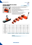
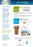
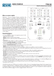
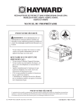
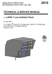
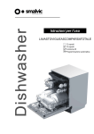
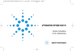
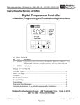
Spectrophotomètre Genova Nano
Accessoire à microvolume
Raccord d'accessoire et manuel d'utilisation
737 555 RÉV. A/03-12
Sécurité
Please read this information carefully prior to installing or using this equipment.
1. The unit described in this manual is designed be operated only by trained personnel. Any
adjustments, m
. aintenance and repair must be carried out as defined in this manual, by a person qualified
to be aware of the hazards involved.
2. It is essential that both operating and service personnel employ a safe system of work, in addition to
the detailed instructions specified in this manual.
3. Other than for those items defined in the maintenance procedures herein there are no user serviceable
items in this instrument. Removal of covers and attempted adjustment or service by unqualified personnel
will invalidate the warranty and may incur additional charges for repair.
4. References should always be made to the Health and Safety data supplied with any chemicals used.
Generally accepted laboratory procedures for safe handling of chemicals should be employed.
5. If it is suspected that safety protection has been impaired in any way, the unit must be made inoperative
and secured against any intended operation. The fault condition should immediately be reported to the
appropriate servicing authority.
Merci de lire attentivement ces informations avant d’installer ou d’utiliser cet appareil.
1. L’appareil décrit dans ce manuel est conçu pour être utilisé uniquement par des personnes formées.
Tout réglage, maintenance ou réparation doit être effectué comme décrit dans ce manuel, par une
personne qualifiée consciente des risques encourus.
2. Il est essentiel que les personnes utilisant et intervenant sur cet appareil respectent les règles de
sécurité de travail, en plus des instructions détaillées précisées dans ce manuel.
3. En-dehors des éléments décrits dans les procédures de maintenance ci-incluses, cet appareil ne
contient aucun élément réparable par l’utilisateur. L’enlèvement des capots et les tentatives de réglage
ou de réparation par des personnes non qualifiées invalide toute garantie et entraîne un risque de frais
de réparation supplémentaires.
4. Toujours se référer aux fiches techniques de santé et de sécurité accompagnant tout produit chimique
utilisé. Respecter les procédures de laboratoire généralement acceptées pour la manipulation en toute
sécurité des produits chimiques.
5. Si l’utilisateur suspecte qu’un problème quelconque puisse mettre en cause la sécurité, l’appareil doit
être rendu inopérant en empêchant son utilisation. Communiquer la défaillance constatée au service de
maintenance compétent.
Bitte lesen Sie diese Hinweise vor Installation oder Gebrauch dieser Ausrüstung sorgfältig durch.
1. Das in diesem Handbuch beschriebene Gerät darf nur von geschultem Personal bedient werden.
Alle Anpassungen, Wartungsarbeiten und Reparaturen müssen entsprechend der Vorgaben in diesem
Handbuch und von einer kompetenten Person, die mit den damit verbundenen Gefahren vertraut ist,
durchgeführt werden.
2. Es ist wichtig, dass sowohl das Bedienungs- als auch das Service-Personal zusätzlich zu den detaillierten
Anweisungen in diesem Handbuch ein sicheres Arbeitssystem einsetzen.
3. Mit Ausnahme der Teile, deren Wartungsverfahren in diesem Handbuch beschrieben sind, enthält
dieses Gerät keine weiteren Teile, die vom Benutzer gewartet werden können. Das Entfernen von
Abdeckungen und Versuche von hierfür unqualifiziertem Personal, Anpassungen oder Wartungsarbeiten
durchzuführen, haben zur Folge, dass die Garantie verfällt und können zusätzliche Reparaturkosten
auslösen.
4. Es ist jederzeit auf die sicherheitsrelevanten Daten sämtlicher verwendeter Chemikalien Bezug zu
nehmen. Allgemein anerkannte Labormethoden zum sicheren Umgang mit Chemikalien sollten
eingesetzt werden.
5. Besteht der Verdacht, dass die Sicherheitsvorrichtungen in irgendeiner Weise beschädigt wurden,
muss das Gerät außer Betrieb genommen und gegen weiteren Gebrauch gesichert werden. Die Störung
sollte der zuständigen Serviceeinrichtung unverzüglich gemeldet werden.
Leggere attentamente queste istruzioni prima di installare o utilizzare il dispositivo.
1. L’unità descritta nel presente manuale è stata realizzata per essere utilizzata solo da personale che ha
ricevuto l’apposita formazione. Qualsiasi operazione di regolazione, manutenzione e riparazione deve
essere effettuata sulla base di quanto indicato nel presente manuale da personale qualificato consapevole
dei rischi connessi.
2. È fondamentale che il personale operativo e il personale addetto alla manutenzione utilizzino un
sistema di lavoro sicuro, oltre a seguire le istruzioni specificate nel presente manuale.
3. Oltre a quelli indicati nelle procedure di manutenzione, all’interno di questo dispositivo non sono
presenti altri elementi sui quali è possibile effettuare interventi. La rimozione delle protezioni e qualsiasi
tentativo di regolazione o di manutenzione posto in essere da personale non qualificato invaliderà la
garanzia. In questi casi, sarà necessario pagare un importo per le riparazioni effettuate.
4. È sempre necessario fare riferimento ai dati sulla salute e sulla sicurezza forniti con le sostanze chimiche
utilizzate. Adottare le procedure di laboratorio generalmente accettate per la gestione delle sostanze
chimiche.
5. Nel caso in cui si sospetti che la salute possa essere pregiudicata in qualsiasi modo, disattivare l’unità
per renderla inutilizzabile. Qualsiasi condizione di errore deve essere immediatamente segnalata al
responsabile per la manutenzione.
Lea esta información atentamente antes de instalar o utilizar este equipo.
1. La unidad descrita en este manual está diseñada para que solamente la utilice personal con formación.
Cualquier operación de ajuste, mantenimiento y reparación debe llevarse a cabo del modo indicado en
este manual y debe realizarla una persona cualificada que sea consciente de los peligros que implica.
2. Es fundamental que tanto los operarios como el personal de servicio utilicen un sistema de trabajo
seguro, así como las instrucciones detalladas que se especifican en este manual.
3. Cualquier elemento que no se encuentre entre los definidos en los procedimientos de mantenimiento
aquí descritos no podrá utilizarse en este instrumento. La extracción de las tapas y los intentos de ajuste
o reparación por parte de personal no cualificado invalidarán la garantía y pueden incurrir en cargos
adicionales por reparación.
4. Siempre deberían consultarse los datos sobre Salud y Seguridad que se suministran con cualquier
producto químico que se utilice. Es necesario llevar a cabo los procedimientos de laboratorio de aceptación
generalizada para la manipulación segura de productos químicos.
5. Si existe la sospecha de que las medidas protectoras de seguridad han quedado dañadas en cualquier
modo, la unidad debe inutilizarse y protegerse contra toda operación que se intente llevar a cabo.
El estado de fallo debe comunicarse inmediatamente a la autoridad de servicio de mantenimiento y
reparación pertinente.
1
Table des matières
2
Page
SECTION 1 - Introduction
1.1 DESCRIPTION DE L'ACCESOIRE À MICROVOLUME
1.2 SPÉCIFICATIONS DE L'ACCESSOIRE À MICROVOLUME
1.3 DÉBALLAGE
3
3
3
4
SECTION 2 – Schéma et installation de l'accessoire
2.1 SCHÉMA DE L'ACCESSOIRE
2.2 RETRAIT DE L'ACCESSOIRE
2.3 INSTALLATION DE L'ACCESSOIRE
2.4 INITIALISATION
5
5
5
7
7
SECTION 3 – Paramètres de l'accessoire
3.1 ACCÈS AUX PARAMÈTRES DE L'ACCESSOIRE À MICROVOLUME
3.2 SÉLECTION DU TRAJET OPTIQUE
3.2.1 Mesures connues de trajet optique
3.2.2 Mesures inconnues de trajet optique
8
8
9
9
9
SECTION 4 – RÉALISATION DE MESURES DE MICROVOLUME
4.1 PIPETTAGE D'ÉCHANTILLONS SUR LA TÊTE DE LECTURE DU MICROVOLUME
4.2 RÉCUPÉRATION OU RETRAIT D'ÉCHANTILLON
10
10
11
SECTION 5 – ÉTALONNAGE DE L'ACCESSOIRE À MICROVOLUME
5.1 SOLUTIONS D'ÉTALONNAGE (035 092)
12
12
5.2 5.2.1
5.2.2 5.2.3 12
12
12
13
PROCÉDURE D'ÉTALONNAGE DE L'ACCESSOIRE
Paramètres de l'accessoire à microvolume
Norme d'étalonnage - Saisie de données Étalonnage et vérification de l'accessoire SECTION 6 – NETTOYAGE ET DÉCONTAMINATION DE L'ACCESSOIRE À MICROVOLUME
6.1 NETTOYAGE DE L'ACCESSOIRE
6.2 DÉCONTAMINATION DE L'ACCESSOIRE
6.3 RECONDITIONNEMENT DE LA TÊTE DE LECTURE
16
16
16
16
SECTION 7 – ACCESSOIRES
7.1 ACCESSOIRES
16
16
SECTION 8 – MAINTENANCE ET RÉPARATION
8.1 MAINTENANCE DE ROUTINE
8.2 RÉPARATION
17
17
17
SECTION 9 – DÉPANNAGE 9.1 CODES D'ERREUR DE L'ACCESSOIRE
9.1.1 Codes d'erreur de la procédure d'étalonnage
9.1.2 Codes d'erreur du contrôle de vérification
9.2 GUIDE DE DÉPANNAGE
9.3 ASSISTANCE TECHNIQUE
18
18
18
18
19
19
SECTION 10 – GLOSSAIRE DES ICÔNES
20
SECTION 11 – COMPATIBILITÉ CHIMIQUE
21
SECTION 1 - INTRODUCTION
1.1 DESCRIPTION DE L'ACCESSOIRE À MICROVOLUME
Le Genova Nano est un spectrophotomètre UV-visible dédié aux analyses biologiques. Ce
spectrophotomètre intègre un accessoire de mesure d'échantillon à microvolume qui permet d'analyser
de faibles volumes d'échantillon de 0,5 μl. Le spectrophotomètre Genova Nano dispose de méthodes
préprogrammées permettant de déterminer des concentrations d'ADN et de rapports de pureté utilisant
des longueurs d'onde enregistrées à 260, 280 et 230 nm, avec une correction facultative à 320 nm, ainsi
que des méthodes de Bradford, Lowry, Biuret, ABC et UV directe pour l'analyse des protéines. Lorsque
l'accessoire à microvolume est retiré, le Genova Nano se convertit en spectrophotomètre Genova Plus
standard intégrant les modes de mesure photométrie, concentration, multi-longueur d'onde, balayage
de spectre, analyse quantitative et cinétique.
Ce spectrophotomètre biologique utilise un logiciel géré par des icônes et présente un système de
navigation amélioré pour une utilisation facile et intuitive.
1.2 SPÉCIFICATIONS DE L'ACCESSOIRE À MICROVOLUME
Genova Nano
Longueur d’onde
Plage
De 198 à 1000 nm
Résolution
1 nm
Précision
± 2 nm
Répétabilité
± 0,5 nm
Largeur de bande spectrale
5 nm
Photométrie
Plage d'absorbance
De -0,300 à 2,500 A
(longueur du trajet optique 10 mm = De -15,0 à 125,0 A)
Précision
±2 %@ 1 A
Précision de l'absorbance
Entre 0 et 1 A = <0,005 ; 1 à 2 A = 2 % ; au-delà de 2 A = 4 %
Limite de détection ADNdb (0,5 mm) 2,0 ng/µl
Maximum
Concentration (0,20 mm)
6000 ng/µl
Lumière parasite
<0,5 % à 340 nm et 220 nm
Autre
Poids
1,5 kg
Trajets optiques
0,2 mm et 0,5 mm
Temps de mesure
<6,5 s
Taille d'échantillon
De 0,5 à 5,0 µl
Température de fonctionnement
De 10 à 40 °C
Humidité en fonctionnement
De 0 à 80 % sans condensation
3
1.3 DÉBALLAGE
Le Genova Nano est livré avec l'accessoire à microvolume préinstallé et emballé en toute sécurité dans la
chambre de prélèvement des spectrophotomètres. L'emballage de protection doit être retiré avant
la première initialisation de l'instrument.
Emballage de
protection du
microvolume
(retirer)
Fig 1.3 – Déballage de l'accessoire à microvolume
4
SECTION 2 – SCHÉMA ET INSTALLATION DE L'ACCESSOIRE
2.1 SCHÉMA DE L'ACCESSOIRE
Raccord de couplage
Tête de lecture
supérieure
Capot de tête de lecture
Trajet optique Moteur
d'entraînement
Tête de lecture
inférieure
Capots latéraux
Fig 2.1 – Schéma de l'accessoire à microvolume
2.2 RETRAIT DE L'ACCESSOIRE
S'il est acheté conjointement au spectrophotomètre Genova Nano, l'accessoire à microvolume est
préinstallé. L'optique de l'accessoire est adaptée au spectrophotomètre sur lequel elle est initialement
installée. Par conséquent, les utilisateurs ne sont pas en mesure de transférer l'accessoire à microvolume
sur d'autres spectrophotomètres Genova Plus/Nano sans l'assistance d'un technicien formé.
L'accessoire à microvolume ne doit pas être retiré ou reposé inutilement car cela pourrait
affecter la précision de l'alignement optique des accessoires.
Conformez-vous aux étapes suivantes pour déposer et reposer l'accessoire à micro-volume dans le
spectrophotomètre Genova Nano.
Déposez le panneau frontal de la chambre de
prélèvement en desserrant les vis 1 et 2 jusqu'à
ce que le panneau frontal puisse être retiré vers
le haut et vers l'avant.
1
2
▼
Déposez le
panneau frontal
5
Déposez les capots latéraux en les tirant vers le haut
Capots
latéraux
Vis 3 et 4
Déposez les vis externes 3 et 4.
Assurez-vous que les vis internes 5 et 6 ne sont
pas serrées/déposées.
Vis 5 et 6
Raccord de couplage
Débranchez le raccord de couplage du support situé
sur la face cachée du couvercle de spectrophotomètre
à l'aide de la clé Allen fournie, puis déposez le capot de
la tête de lecture.
Capot de tête de lecture
Vue avec couplage débranché et capot de tête de
lecture déposé.
6
Levez soigneusement l'accessoire à microvolume de la
chambre de prélèvement du spectrophotomètre en le
tournant vers le côté droit de façon à ce que l'optique du
détecteur éclairé ne se cogne pas pendant le retrait de
l'accessoire.
Optique de détecteur
Tournez
l'accessoire sur la
droite pour le retirer.
Finally
disconnect
thele power
and communication
cable
Enfin,
débranchez
câble d'alimentation
et de commude la face
du circuitPCB.
imprimé de l'accesfrom nication
the underside
of cachée
the accessory
soire.
2.3
2.3
INSTALLATION DE L'ACCESSOIRE
ACCESSORY INSTALLATION
Pour installer l'accessoire à micro-volume, inversez la procédure décrite dans la Section 2.2.
The micro volume accessory is installed by reversing the procedure described in Section 2.2.
2.4
2.4
INITIALISATION
INITIALISATION
Connect the power supply unit to the power inlet socket on the rear panel of the instrument and
Branchez l'unité d'alimentation électrique à la prise d'entrée d'alimentation sur le panneau arrière de
connect tol'instrument,
the mains socket.
Turn theaux
power
ondu
at réseau
the mains
and switch
the instrument
on using et
the
puis connectez-la
prises
électrique.
Pour allumer
le réseau électrique
l'instrument,
appuyez
surinstrument.
l'interrupteur situé à l'arrière de l'instrument.
power switch
on the rear
of the
L'instrument
vérifiera check
d'abordfor
les mises
à jourupdates
de micrologiciel,
puisperform
procèderaseveral
à plusieurs
tests de mise
The
instrument
will initially
firmware
and then
power-on
tests
sous tension avant d'afficher le menu principal :
before displaying the main menu:
Fig
– Genova
Nano
Menu
Fig
2.22.2
– Menu
principal
du Main
Genova
Nano
7
SECTION
3 – ACCESSORY
SETTINGS
SECTION
3 – PARAMÈTRES
SECTION 3 – ACCESSORY SETTINGS
DE L'ACCESSOIRE
3.1
ACCESSING THE MICRO VOLUME ACCESSORY SETTINGS
3.1
ACCESSING THE MICRO VOLUME ACCESSORY SETTINGS
3.1 ACCÈS AUX PARAMÈTRES DE L'ACCESSOIRE À MICROVOLUME
When installed, the micro volume accessory icon is displayed in the bottom right hand corner of the
Lorsqu'il the
est installé,
l'icône de
l'accessoire
à microvolume
dans le coin
droit deofl'écran
When installed,
micro volume
accessory
icon
is displayeds'affiche
in the bottom
rightinférieur
hand corner
the
screen in each measurement mode.
dans chaque mode de mesure.
screen in each measurement mode.
Micro Volume Accessory
icon
Icône
à
Microd'accessoire
Volume Accessory
icon the micro volume
microvolume
The micro volume accessory settings are accessed by pressing the key below
accessory
icon. accessory settings are accessed by pressing the key below the micro volume
The
micro
Lesvolume
paramètres
de l'accessoire à microvolume sont disponibles via une simple pression sur la touche
accessory
icon.
située
en dessous
de l'icônesettings
d'accessoire
The micro
volume
accessory
allowà microvolume.
the user to select the required path length for a
measurement
and calibrate
the settings
accessory
usingthe
a standard
with
absorbance
values
at a
Les paramètres
de l'accessoire
à microvolume
permettent
à l'utilisateur
de sélectionner
trajet optique
The
micro
volume
accessory
allow
user tosolution
select
theknown
required
path le
length
for
souhaité
260 and
330nm.pour une mesure et d'étalonner l'accessoire à l'aide d'une solution-étalon avec des valeurs
measurement and calibrate the accessory using a standard solution with known absorbance values at
d'absorbance connues à 260 et 330 nm.
260 and 330nm.
Paramètre de trajet
0.2mm Path
Length
optique
0,2 mm
Setting Paramètre de trajet
optique
0,5 mm
0.2mm
Path
Length
0.5mm
Path
Length
Setting
Setting Paramètre de
optique
Auto Path
Length
0.5mm
Pathtrajet
Length
automatique
Setting
Setting
Étalonnage
Auto Path Length
trajet
Path de
Length
Setting
optique
Calibration
Path Length
Calibration
Icône
de validation
Tick icon
A260 Calibration
Valeur
standard
Standard
d'étalonnage
A260 VIDE
Tick iconValue
Valeur
standard
AA
Calibration
Calibration
330
260
d'étalonnage
A330 VIDE
Standard
Value
Standard
Value
Valeur
trajet
Calibration
Standard
A330 de
Calibration
optique
d'étalonnage
Path
Length
Value
Standard Value
standard
Calibration Standard
Path Length Value
Mode d'alignement
Accessory
de l'accessoire
Alignment
Mode
Facteurs
Current
Calibration
d'étalonnage
Factors
actuels
Current Calibration
Accessory
Fig
Micro
Accessory
Settings Menu
Fig 3.1
3.1 ––Factors
Menu Volume
des paramètres
de Alignment
l'accessoire
à microvolume
Mode
Fig 3.1 – Micro Volume Accessory Settings Menu
12
12
8
3.2 SÉLECTION DU TRAJET OPTIQUE
3.2
PATH LENGTH SELECTION
3.2.1 3.2
LENGTH
SELECTION
Mesures
connues
de Length
trajet
optique
3.2.1 PATH
Known
Path
Measurements
3.2.1 Known Path Length Measurements
Si le required
trajet optique
de mesure path
est connu,
être it
If the
measurement
lengthil peut
is known
sélectionné en appuyant sur la touche située à côté
selected
by pressing path
the button
Ifcan
thebe
required
measurement
length adjacent
is known to
it
des icônes de paramètres de trajet optique 0,2 mm
the
0.2mm
or
0.5mm
path
length
setting
icons.
The
can
selected
pressingsélectionné
the buttonestadjacent
oube
0,5 mm.
Le by
paramètre
indiqué to
selected
is indicated
by
anque
icon
with
a black
par
unesetting
icône
avec
fond
noir.
Dès
le paramètre
the
0.2mm
or 0.5mm
path
length
setting
icons.
The
de trajet
optique
estbysélectionné,
appuyez
background.
Once
the required
selected
setting
is souhaité
indicated
anpath
iconlength
with
asetting
black
sur
le
bouton
situé
près
de
l'icône
de
validation
has
been
selected
press
the
button
adjacent
to
the
background. Once the required path length setting
pour confirmer.
tick icon
confirm. press the button adjacent to the
has
beentoselected
tick icon to confirm.
3.2.2 Unknown Path Length Measurements
3.2.2 Mesures
inconnues
de Length
trajet optique
3.2.2 Unknown
Path
Measurements
If the required measurement path length is not
path
length
setting
can
be connu,
selected
Sithele the
trajetauto
optique
de mesure
n'est
pas
Ifknown
required
measurement
path
length
is not
le
paramètre
de
trajet
optique
automatique
peut
by pressing
thepath
button
adjacent
thebeauto
path
known
the auto
length
settingtocan
selected
être sélectionné en appuyant sur la touche située
length
settingthe
icon. Once adjacent
the auto path
length
by
pressing
to longueur
the
autosetting
path
près
de l'icône button
de paramètre de
de
has
been
selected
press
the
button
adjacent
to
the
length
icon.
Once the auto
pathlelength
setting
trajetsetting
optique
automatique.
Dès que
paramètre
tick
toselected
confirm.
deicon
trajet
optiquepress
automatique
estadjacent
sélectionné,
has
been
the button
to the
appuyez sur la touche située près de l'icône de
tick icon to confirm.
validation pour confirmer.
The auto path length measurement setting will firstly measure a sample using the 0.5mm path length
setting.
the measured
photometricsetting
value will
is within
theavalue
willusing
be displayed
on path
screen
and
The
autoIf path
length measurement
firstlyrange,
measure
sample
the 0.5mm
length
the on
sample
willand
be
no moreIf measurements
are taken. Ifvalue
however
the measured
over-range,
setting.
the measured photometric
is within
range, thevalue
valueiswill
be displayed
screen
Le paramètre using
de mesure
de trajet
mesurera d'abord un échantillon à l'aide du paramètre
re-measured
the 0.2mm
pathoptique
length
setting.
no
more measurements
are taken.
If however
the measured value is over-range, the sample will be
de trajet optique 0,5 mm. Si la valeur photométrique mesurée est comprise dans la plage, la valeur
re-measured
using the
0.2mm
path mesure
length setting.
s'affichera à l'écran
et plus
aucune
ne sera effectuée. Toutefois, si la valeur mesurée est hors
plage, l'échantillon sera mesuré de nouveau à l'aide du paramètre de trajet optique 0,2 mm.
13
13
9
SECTION 4 – RÉALISATION DE MESURES DE MICROVOLUMES
Pour obtenir des descriptions détaillées des modes de mesure disponibles sur le spectrophotomètre
Genova Nano, veuillez vous reporter au manuel d'utilisation Genova Plus fourni.
4.1 PIPETTAGE D'ÉCHANTILLONS SUR LA TÊTE DE LECTURE À MICROVOLUME
Le spectrophotomètre Genova Nano est conçu pour mesurer des volumes d'échantillons dans la plage
de 0,5 μl à 5,0 μl.
Jenway recommande aux utilisateurs des échantillons d'au moins 2 μl pour la réalisation des
mesures, si possible.
1. Ouvrez le mécanisme de tête de lecture, puis utilisez
une pipette pour verser le liquide à analyser au
centre de la tête de lecture inférieure.
Pipettage d'un échantillon sur la tête de lecture
2. Fermez le couvercle du spectrophotomètre. Cette
action descendra l'ensemble de tête de lecture sur
le moteur d'entraînement du trajet optique. La tête
de lecture supérieure sera alors en position de repos,
2 mm au-dessus de la tête de lecture inférieure.
Tête de lecture en position de repos
3. Lorsqu'une mesure est lancée, le moteur
d'entraînement de trajet optique descend la tête de
lecture supérieure à la distance de mesure spécifiée,
la mesure photométrique est prise et la tête de
lecture supérieure est ensuite renvoyée en position
de repos.
Tête de lecture en position de mesure
10
4.2 RÉCUPÉRATION OU RETRAIT D'ÉCHANTILLON
Dès qu'une mesure est terminée, la solution d'échantillon peut être récupérée sur la tête de lecture
inférieure à l'aide d'une pipette adaptée ou retirée des têtes de lecture par un nettoyage avec un chiffon
non-pelucheux adapté.
1. Ouvrez le couvercle du spectrophotomètre. Le
mécanisme de tête de lecture s'ouvre et donne
accès aux têtes de lecture supérieure et inférieure.
2. L'échantillon peut être récupéré en aspirant
soigneusement le liquide retenu sur la tête de lecture
inférieure à l'aide d'une pipette propre.
3. Les têtes de lecture doivent ensuite être essuyées
avec un chiffon non-pelucheux.
4.Un nettoyage plus rigoureux peut être requis après la mesure d'échantillons à forte concentration ou
d'échantillons présentant un risque de contamination. Voir la section 6 pour plus de détails.
11
SECTION 5 – ÉTALONNAGE DE L'ACCESSOIRE À
SECTION
5 – CALIBRATION OF THE MICRO VOLUME ACCESSORY
MICROVOLUME
SECTION 5 – CALIBRATION OF THE MICRO VOLUME ACCESSORY
5.1 Jenway
recommendsunthat
the micro
volume accessory
is calibrated
everyUn
6 kit
months.
A set of
Jenway recommande
étalonnage
de l'accessoire
à microvolume
tous les 6 mois.
de solutions
Jenway
recommends
thatcode
the 035
micro
accessory
every spectrophotometer.
6Nano.
months. A set of
d'étalonnage
(code de
pièce
035
092)
estvolume
fourni
avec
le spectrophotomètre
Genova
calibration
solutions
(Part
092)
are supplied
withisthecalibrated
Genova Nano
calibration solutions (Part code 035 092) are supplied with the Genova Nano spectrophotometer.
5.1
CALIBRATION SOLUTIONS (035 092)
SOLUTIONS
D'ÉTALONNAGE
(035 092)
5.1
CALIBRATION
SOLUTIONS
(035 092)
Étiquette
bleu
Étiquette
blanche
1
5.2 5.2.1 2
The supplied
calibration
setdeconsists
of
La solution
d'étalonnage
fournie solution
se compose
deux
The
supplied
calibration
solution
set
consists
of
fioles.
two vials.
two vials.
1. Blanc de matrice (blanc)
1. Matrix Blank (White)
1.
Matrix
Blankd'étalonnage
(White)
2. 10x réf.
- Norme
(bleu)
2. 10x ref - Calibration Standard (Blue)
10x ref
- Calibrationfourni
Standard
(Blue)
Un 2.
certificat
d'étalonnage
détaille
les valeurs
A calibration
certificate
is supplied
that details
d'absorbance
certifiées
de la norme
d'étalonnage
et the
A calibration certificate is supplied that details the
le trajet
optiqueabsorbance
ayant servi à la
détermination
ces
certified
values
of the decalibration
certified absorbance values of the calibration
valeurs.
standard and the path length at which these values
standard and the path length at which these values
were determined.
were determined.
5.2
ACCESSORY CALIBRATION PROCEDURE
5.2
ACCESSORY
CALIBRATION
PROCEDURE
PROCÉDURE
D'ÉTALONNAGE
DE L'ACCESSOIRE
5.2.1
Micro Volume
AccessorySettings
Settings
5.2.1 Micro
Volume Accessory
Paramètres
de l'accessoire
à microvolume
Les paramètres
l'accessoire
à microvolume
sont
The micro
microde
volume
accessory
settings
The
volume
accessory
settings
cancan
be be
accessibles en appuyant sur la touche située en dessous
accessedbybypressing
pressingthethekeykey
below
Micro
accessed
below
thethe
Micro
de l'icône
d'accessoire à microvolume
dans
l'ensemble
Volume
Accessoryicon
icondu
anyof of
Genova
in in
any
thethe
Genova
des Volume
modes
deAccessory
fonctionnement
Genova
Nano.
Nano’soperating
operating
modes.
Nano’s
modes.
Icône de l'accessoire à microvolume
5.2.2
5.2.2
5.2.2 Calibration Standard
Calibration
Standard -- Data
DataEntry
Entry
Norme d'étalonnage - Saisie de données
1.1. Enter
A330DNA
DNAstandard
standard
Enter the
theA260
A260and
andA330
1.Saisissez les valeurs de solution-étalon ADN A260
solution
values
from
the
supplied
calibration
solution values from the supplied calibration
et A330 d'après le certificat d'étalonnage fourni
accessory
into
accessory
settingsby by
certificate
into
the
dans certificate
les
paramètres
dethe
l'accessoire
en settings
appuyant
the
to to
thethe
Calibration
sur lapressing
touche située
près
de
l'icône
de
valeur
de
pressing
thekey
keyadjacent
adjacent
Calibration
norme
d'étalonnage. icon.
Standard
StandardValue
Value icon.
16
16
12
2. 2.
Sélectionnez
chiffre
à changed
modifier àusing
l'aide
Select theledigit
to be
thedes
keys
2.touches
Selectsituées
the digit
to be
using thede
keys
dans
la changed
partie inférieure
at the bottom of the screen. Use the keys
2.
Select
the
digit
to
be
using
the
keys
lesof
situées
près
at
theUtilisez
bottom
the changed
screen.
Use
the
2.l'écran.
Select
the
digit
totouches
be
changed
using
thedes
keys
adjacent to the arrow icons to increase or
icônes
de
flèche
pour
augmenter
ou
diminuer
le
at
the
bottom
of
the
screen.
Use
the
keys
icons to
increase
or
adjacent
to theofarrow
at
the bottom
the screen.
Use
the keys
decrease the number. Press the key adjacent
chiffre.
icons
to
increase
or
adjacent
arrow
decrease to
thethe
number.
adjacent
iconsthe
to key
increase
or
adjacent
to
the
arrowPress
to the tick icon to save any changes.
decrease
the
number.
Press
the
key
adjacent
to the sur
tick la
icon
to save
any
changes.
decrease
the
number.
Press
the
adjacent
Appuyez
touche
située
près
de key
l'icône
de
to
the
tick
icon
to
save
any
changes.
validation
pour
enregistrer
to the tick
icon
to save les
anymodifications.
changes.
Enter the
stated
pathdéclaré
length (1.0mm
forlethe
3.3.
le trajet
optique
pour
3.Saisissez
Enter the
stated
path length(1,0 mm
(1.0mm
for the
calibrationd'étalonnage
standard solution
kitsupplied
de solution-étalon
fourni) set)
pour for
3.
the
stated
path
length
(1.0mm
for
supplied
standard
set)
for
3.lesEnter
Enter
the calibration
stated
path
length solution
(1.0mm
for the
the
valeurs
solution-étalon
en mm,
dans
the
DNAdestandard
solutionADN,
values,
in mm,
into
supplied
standard
solution
set)
for
the
DNA calibration
standard
solution
in mm,
calibration
standard
solution
set)lainto
for
lessupplied
paramètres
de l'accessoire
envalues,
appuyant
sur
the accessory settings by pressing the key
the
DNA
standard
solution
values,
in
mm,
into
touche
située
prèssettings
de solution
l'icônebydevalues,
valeur in
demm,
trajetinto
pressing
the
key
the accessory
DNA
standard
adjacent to the Calibration Standard Path
optique
de
la
norme
d'étalonnage.
accessory
settings
by
pressing
the
key
the
adjacent
to the
Calibration
Standard
accessory
settings
by pressing
the Path
key
the
Length Value icon.
adjacent
to
the
Calibration
Standard
Path
Length
Value
icon.
adjacent to the Calibration Standard Path
Length
Length Value
Value icon.
icon.
4. Select the digit to be changed using the keys at the bottom of the screen. Use the keys
4. Select the digit to be changed using the keys at the bottom of the screen. Use the keys
4. Sélectionnez
à modifier
l'aide desortouches
situées
dans la partie
de l'écran.
adjacent le
to chiffre
the arrow
icons toà increase
decrease
the number.
Press inférieure
the key adjacent
to the
4.
Select
the
to
changed
using
the
keys
the number.
bottom
of
the
screen.
Use
the
adjacent
to digit
thesituées
arrow
icons
increase
or decrease
the
Press
adjacent
the
Utilisez
les touches
près
destoicônes
de flèche
pourat
augmenter
ou diminuer
ce key
chiffre.
Appuyez
4.
Select
the
digit
to be
be
changed
using
the
keys
at
bottom
of
the the
screen.
Use
the tokeys
keys
tick icon to save any changes.
adjacent
to
the
arrow
icons
to
increase
or
decrease
the
number.
Press
the
key
adjacent
to
the
sur la
touche
située
l'icône
validation
pour enregistrer
les modifications.
tick
icon to
anyde
changes.
adjacent
to save
the près
arrow
icons
to de
increase
or decrease
the number.
Press the key adjacent to the
5.2.3 tick
Accessory
Calibration
and Verification
icon
any
icon to
to save
save
any changes.
changes.
5.2.3 tickAccessory
Calibration
and Verification
If
an
error
message
is
displayed
during
the accessory calibration and verification procedure,
5.2.3
Accessory
Calibration
and
Verification
5.2.3 Étalonnage
et vérification
de l'accessoire
Calibration
Verification
If5.2.3
an errorAccessory
message is
displayedand
during
the accessory calibration and verification procedure,
refer to Section 9 for further details.
If
an
error
message
is
displayed
during
the
calibration
and
procedure,
Si
un
message
d'erreur
s'affiche
pendant
la procédure
d'étalonnage
et de vérification
de
refer
to Section
9 forisfurther
details.
If
an error
message
displayed
during the accessory
accessory
calibration
and verification
verification
procedure,
l'accessoire,
reportez-vous
à la Section 9 pour plus de détails.
refer
refer to
to Section
Section 9
9 for
for further
further details.
details.
1. The accessory calibration sequence is initiated
1. The accessory calibration sequence is initiated
by pressing
keysituée
adjacent
Path
1.1.Appuyez
sur la the
touche
près to
de isthe
l'icône
accessory
calibration
sequence
initiated
by pressing
key adjacent
to
Path
1. The
The
accessorythe
calibration
sequence
isthe
initiated
Length Calibration
icon.
d'étalonnage
de
trajet
optique
pour
lancer
la
adjacent
by
pressing
the
key
Length
Calibration
by
pressing
the icon.
key
adjacent to
to the
the Path
Path
séquence
d'étalonnage
de l'accessoire.
Length
Calibration
icon.
Length Calibration icon.
2. The Air Measurement icon will be displayed.
2. The Air Measurement icon will be displayed.
Use a lint free cloth to clean the upper and
The
Measurement
icon
will
be
displayed.
2.2.
mesure
d'air tos'affiche.
Utilisez
unand
Use Air
adelint
free cloth
clean
upper
2.L'icône
The
Air
Measurement
icon
willthe
be
displayed.
lower
read
heads,
close
the
instrument
lid
and
chiffon
non-pelucheux
pour
nettoyer
les têtes
Use
lint
free
to
clean
the
lowera
close
instrument
lid and
Use
aread
lint heads,
free cloth
cloth
to the
clean
the upper
upper
and
key adjacent
to the fermez
tick icon
depress
lecturethesupérieure
et inférieure,
le to
lower
read
heads,
close
the
instrument
lid
and
press read
the heads,
key adjacent
to instrument
the tick icon
to
lower
close the
lid and
couvercle
l'instrument
continue.dePressing
the et
keyappuyez
adjacentsurto lathe
press
the
key
adjacent
to
the
tick
to
continue.
the key
adjacent
to the
press
the Pressing
key de
adjacent
to validation
the
tick icon
icon
to
touche
située
près
l'icône
de
pour
cross icon will return the instrument to the
continue.
Pressing
the
key
adjacent
to
the
continuer.
Appuyez
sur la
située prèstodethe
cross icon
will return
the
adjacent
continue.
Pressing
thetouche
keyinstrument
micro volume accessory settings menu screen.
l'icône
de
croix
pour
revenir
à
l'écran
du menu
cross
icon
will
return
the
instrument
to
micro volume
accessory
settings
menu
screen.
cross
icon will
return the
instrument
to the
the
desmicro
paramètres
de
l'accessoire
à
micro-volume.
micro volume
volume accessory
accessory settings
settings menu
menu screen.
screen.
L'appareil produit cinq relevés clairs et obscurs à17
260 et 330 nm, avec à la fois les trajets optiques17
17
0,5 et 0,2 mm.
17
13
The unit takes five dark and light readings at
The unit takes five dark and light readings at
260
at dark
both and
the light
0.5 and
0.2mm
The and
unit 330nm,
takes five
readings
at
260 and 330nm, at both the 0.5 and 0.2mm
pathlengths.
260 and 330nm, at both the 0.5 and 0.2mm
pathlengths.
pathlengths.
3.3. The
Blank
Solution
Measurement
will be
L'icône
de mesure
de solution
à blanc icon
s'affiche.
3. The Blank Solution Measurement icon will be
Ouvrez
le couvercle
l'instrument
puis,
Open
the de
instrument
lid and
pipette
3. displayed.
The Blank
Solution
Measurement
icon
willà be
displayed.
the placez
instrument
and pipette
l'aide
d'uneOpen
pipette,
une lid
aliquote
de
adisplayed.
2.0μl aliquot
of the matrix
blanklidsolution
onto
Open
instrument
and pipette
a 2.0μldealiquot
of theà matrix
blank
solution
onto
2,0 μl
la solution
blanc de
matrice
sur la
the
lower
readinférieure.
head.
Close blank
the instrument
lid
a 2.0μl
aliquot
of
the matrix
solution onto
tête
de
lecture
the lower read head. Close the instrument lid
press
the key
adjacent
icon to
the lower
read
head.
Close tothetheinstrument
lid
and
Fermez
le couvercle
l'instrument
et tick
appuyez
and press
the key de
adjacent
to the
tick
icon to
initiate
the blank
measurement.
sur
touche
située
près
de l'icône
andla press
the
key
adjacent
to de
thevalidation
tick icon to
initiate the blank measurement.
pour
lancer
la
mesure
à
blanc.
initiate
blank
4. The
unitthe
takes
fivemeasurement.
readings at 260 and 330nm,
4.
The
unit
takes
five readings
at 260à and
4. L'appareil produit
cinq relevés
260330nm,
et
both
the
0.5 and
0.2mm
pathlengths.
4. at
The
unit
takes
five
readings
at
260
and
330nm,
330 nm,
à
la
fois
pour
les
trajets
optiques
0,5
at both the 0.5 and 0.2mm pathlengths.
at 0,2 mm.
both the 0.5 and 0.2mm pathlengths.
et
5. If the measured values are within the required tolerances, the Passes Test icon will be
If the
measured
are withindans
the les
required
tolerances,
Passes
Test icon
5. 5.
Si les
valeurs
mesuréesvalues
sont comprises
tolérances
requises, the
l'icône
de validation
de will
test be
Press the
buttonare
adjacent
Tick icon
to continuethe
or Passes
the button
adjacent
to the
5. displayed.
If the measured
values
within to
thetherequired
tolerances,
Test
icon will
be
displayed.
Press
to l'icône
the Tick
to continue
or the button
adjacent
to the
s'affiche.
Appuyez
surthe
la button
touche adjacent
située près
deicon
validation
pour continuer
ou sur
le bouton
Cross
to
cancel
the
calibration
process.
displayed.
Press
button
adjacent
the Tick d'étalonnage.
icon to continue or the button adjacent to the
situé
près icon
de l'icône
dethe
croix
annuler
letoprocessus
Cross
icon
to cancel
the pour
calibration
process.
Cross icon to cancel the calibration process.6. The Calibration Solution Measurement icon will
6. L'icône
de mesure
de la solution
d'étalonnage
6.
The Calibration
Solution
Measurement
icon will
Open
the instrument
lid and
s'affiche.
Ouvrez
le couvercle
de l'instrument
6. be
Thedisplayed.
Calibration
Solution
Measurement
iconuse
will
be displayed. Open the instrument lid and use
et
utilisez
un Open
chiffon
non-pelucheux
pouruse
a
free cloth
to
clean
read heads.
belint
displayed.
thethe
instrument
lid and
a lint freelescloth
clean
the read heads.
nettoyer
têtestode
lecture.
a lint free
clothaliquot
to clean
heads.solution
7. Pipette
a 2.0μl
ofthe
theread
calibration
7. À
l'aidead'une
pipette,of placez
une aliquote
7.
Pipette
2.0μl aliquot
the calibration
solution
thealower
read
head.
Close
the
instrument
7. onto
Pipette
2.0μl
aliquot
of the
calibration
solution
de
2,0 μl
de
solution
d'étalonnage
sur
la
tête
onto the lower read head. Close the instrument
de
lecture
inférieure.
Fermez
le
couvercle
de to
lid
andthe
press
theread
keyhead.
adjacent
to the
icon
onto
lower
Close
the tick
instrument
lid and press the key adjacent to the tick icon to
l'instrument
et appuyez
sur la touche située
initiate
calibration
lid andthe
press
the key solution
adjacentmeasurement.
to the tick icon to
initiate
calibration
solution pour
measurement.
près
dethe
l'icône
de validation
lancer la
initiate
the
calibration
solution
measurement.
8. The
unitde
takes
five readings
at 260 and 330nm,
mesure
la solution
d'étalonnage.
8. The unit takes five readings at 260 and 330nm,
at
both
the
0.5 and
pathlengths.
8. L'appareil
produit
cinq relevés
à and
260330nm,
et
8.
The
unit
takes
five 0.2mm
readings
at 260
at both the 0.5 and 0.2mm pathlengths.
330 nm,
à la0.5
fois
pour les trajets
optiques 0,5
at both
the
and
9. If the measured values are within the required
tolerances,
the 0.2mm
Passespathlengths.
Test icon will be
et
0,2 mm.
9. If the measured values are within the required tolerances, the Passes Test icon will be
Press the
buttonare
adjacent
Tick icon
to continuethe
or Passes
the button
adjacent
to the
9. displayed.
If the measured
values
within to
thetherequired
tolerances,
Test
icon will
be
displayed.
Press thesont
button
adjacent
to the
icon torequises,
continuel'icône
or thede
button
adjacent
to the
9. Si les
valeurs mesurées
comprises
dans
les Tick
tolérances
validation
de test
Cross
icon to
cancel
the
calibration
process.
displayed.
Press
button
adjacent
to l'icône
the Tick
to continue
or the button
adjacent
to the
s'affiche.
surthe
la the
touche
située process.
près
deicon
validation
pour continuer
ou sur
le bouton
Cross Appuyez
icon to cancel
calibration
icon
to cancel
the pour
calibration
process.
situéCross
près de
l'icône
de croix
annuler
le processus
d'étalonnage.
10. The
Calibration Solution Measurement icon will
10. The Calibration Solution Measurement icon will
10.
L'icône
de mesure
de
solution
d'étalonnage
Open
for
a lasecond
time.
10. be
Thedisplayed
Calibration
Solution
Measurement
icon the
will
be displayed for a second time. Open the
s'affiche
pendant
une
seconde.
Ouvrez
le
instrument
lid and
a lint free
clothOpen
to clean
the
be displayed
for use
a second
time.
instrumentdelidl'instrument
and use a et
lintutilisez
free cloth
to clean
couvercle
un chiffon
the
read heads.
instrument
lid and use a lint free cloth to clean
non-pelucheux
the read heads. pour nettoyer les têtes de
the reada heads.
lecture.
11. Pipette
2.0μl aliquot of the calibration solution
11. Pipette a 2.0μl aliquot of the calibration solution
11. À
l'aide
d'une
pipette,
placez
une
thealower
head.
Close
the aliquote
instrument
11. onto
Pipette
2.0μl read
aliquot
of the
calibration
solution
onto
the
lower
read
head.
Close
de 2,0 μl de solution d'étalonnagethe
surinstrument
la tête
lid
andthe
press
theread
keyhead.
adjacent
to the
icon to
onto
lower
Close
the tick
instrument
de
lecture
inférieure.
Fermez letocouvercle
de to
lid and
press
the key adjacent
the tick icon
initiate
the
calibration
solution
measurement.
lid
and
press
the
key
adjacent
to
the
tick
icon
l'instrument
et appuyez
sur la measurement.
touche située to
initiate the calibration
solution
près
dethe
l'icône
de validation
lancer la
initiate
calibration
solution pour
measurement.
mesure de la solution d'étalonnage.
18
18
12.
18 L'appareil produit cinq relevés à 260 et 330 nm, avec à la fois les les trajets optiques 0,5
et 0,2 mm.
13. Si les valeurs mesurées sont comprises dans les tolérances requises, l'icône de validation de test
s'affiche et l'instrument calcule les nouveaux facteurs d'étalonnage de trajet optique. Appuyez sur
la touche située près de l'icône de validation pour continuer ou sur la touche située près de l'icône
de croix pour annuler le processus d'étalonnage.
14. Les nouvelles valeurs de facteur d'étalonnage doivent maintenant être vérifiées en mesurant de
nouveau les valeurs air, blanc et étalon.
14
14. The new calibration factor values must now be verified by re-measuring the air, blank and
15. The Air Measurement icon will be displayed.
standard values.
Open the instrument lid and use a lint free
15.15.
L'icône
de
mesure
d'airread
s'affiche.
Ouvrez
lethe
The Air
icon
will be
displayed.
cloth
to Measurement
clean the
heads.
Close
couvercle de l'instrument et utilisez un chiffon
Open the instrument
lid the
and key
useadjacent
a lint free
instrument
lid and press
to
non-pelucheux pour nettoyer les têtes de
cloth Fermez
to clean
thetoreadinitiate
Closeblank
the
tick
icon
the
lecture.
le couvercle
deheads.
l'instrument
etthe
instrument
and press
the key
adjacent
measurement.
appuyez
sur lalid
touche
située près
de l'icône
de to
validation
pour lancer
à blanc.
the tick
icon latomesure
initiate
the blank
16. The unit takes three dark and light readings at
16. L'appareil
produit
trois
relevés
clairs
et
obscurs
à
measurement.
260
and
330nm,
at
both
the
0.5
and
0.2mm
260 et 330 nm, à la fois pour les trajets optiques
16.
The
unit takes three dark and light readings at
0,5pathlengths.
et 0,2 mm.
260 de
andmesure
330nm,
both the
0.5 s'affiche.
and 0.2mm
17. L'icône
de at
solution
à blanc
17.
The
Blank
Solution
Measurement
icon
will be
Ouvrez
le couvercle de l'instrument puis,
à l'aide
pathlengths.
d'une
pipette,Open
placezthe
uneinstrument
aliquote delid
2,0 μl
la
displayed.
and de
pipette
solution
à
blanc
de
matrice
sur
la
tête
de
lecture
17. aThe
Blank
Solution
Measurement
iconsolution
will be
2.0μl
aliquot
of the
matrix blank
inférieure. Fermez le couvercle de l'instrument
displayed.
instrument
and pipette
the
onto
the Open
lowertheread
head.lid Close
et appuyez sur la touche située près de l'icône
a 2.0μl aliquot
of press
the matrix
blank
solution
lid and
the key
adjacent
to
deinstrument
validation pour
lancer
la mesure
à blanc.
Closeblank
onto tick
the lower
read initiate
the
icon
to
the
18. L'appareil
produit
trois relevés
à head.
260 et 330 nm,
àthe
instrument
andoptiques
press the
adjacent to
measurement.
la fois
pour les lid
trajets
0,5key
et 0,2 mm.
the tick icon to initiate the blank
18. The unit takes three readings at 260 and
measurement.
19. Si les valeurs mesurées sont comprises dans les tolérances
requises, l'icône de validation de test
330nm, at both the 0.5 and 0.2mm
s'affiche. Appuyez sur la touche située près l'icône de validation pour continuer ou sur le bouton
18. pathlengths.
The unit takes three readings at 260 and
situé près de l'icône de croix pour annuler le processus
20.d'étalonnage.
The Calibration Solution Measurement icon
330nm, at both the 0.5 and 0.2mm
will be displayed.
OpenTest
the icon
instrument
19. If the measured values are within the required
tolerances,
the Passes
will be lid and
pathlengths.
20. 20.
L'icône
de
mesure deSolution
la solution
d'étalonnage
The
Calibration
Measurement
icon
displayed. Press the button adjacent to the Tick
icon
to
continue
or the
button
adjacent
the heads
use
a lintlefree
cloth
to l'instrument
clean
thetoet
read
s'affiche.
Ouvrez
couvercle
de
will be displayed. Open the instrument lid and
19. Cross
If the icon
measured
values
are withinprocess.
the required
the
Passes lid
Test
icon
will bea 2.0μl
utiliseztolerances,
un chiffon
pour
nettoyer
to cancel
the calibration
Open
the non-pelucheux
instrument
and
pipette
use a lint free cloth to clean the read heads
les têtes
lecture.orOuvrez
le couvercle
dethe
displayed. Press the button adjacent to the Tick
icon todecontinue
button
adjacent to
aliquot
of the the
calibration
solution
onto the
Open
the
instrument
lid
and
pipette
a
2.0μl
l'instrument puis, à l'aide d'une pipette, placez
Cross icon to cancel the calibration process.
lowerofde
read
head.
Close
the
instrument
unealiquot
aliquote
2,0 μl
de solution
d'étalonnage
the
calibration
solution
onto the lid and
sur lower
la press
tête
lecture
inférieure.
leandicon to
key
adjacent
toFermez
the lidtick
readdethe
head.
Close
the instrument
couvercle de l'instrument et appuyez sur la
press
the the
key calibration
adjacent tosolution
the tickmeasurement.
icon to
initiate
touche située près de l'icône de validation pour
initiate
the calibration
solution
measurement.
lancer
la mesure
de la solution
d'étalonnage.
21. The unit takes three readings at 260 and 330nm, at both the 0.5 and 0.2mm pathlengths.
21. 21.
L'appareil
troisreadings
relevés at
à 260
et 330 nm,
à la
foisthe
pour
les trajets
0,5 et
The unitproduit
takes three
260 and
330nm, at
both
0.5 and
0.2mmoptiques
pathlengths.
19
22.0,2 mm.
If the measured values are within the required tolerances, the Passes Test icon will be
If the
measured
values
are withindans
the les
required
tolerances,
Passes
Test icon
22. 22.
Si les
valeurs
mesurées
sont comprises
tolérances
requises, the
l'icône
de validation
de will
test be
displayed. Press the button adjacent to the Tick icon to continue or the button adjacent
19 to the
s'affiche.
Appuyez
sur la
touche
située près
l'icône
validation
pour or
continuer
ou sur
le bouton
displayed.
Press the
button
adjacent
to the
Tickde
icon
to continue
the button
adjacent
to the
Cross
icon
to
cancel
the
calibration
process
situé
près
de
l'icône
de
croix
pour
annuler
le
processus
d'étalonnage.
Cross icon to cancel the calibration process
23. L'affichage
de
l'instrument
revientwill
à l'écran des
instrument
display
to the micro
23.23.
TheThe
instrument
display
will return return
to the micro
paramètres de l'accessoire à microvolume et les
volume
accessory
settings
screen
volume
accessory
settings
and theand the
nouveaux
facteurs
d'étalonnage
descreen
trajet optique
s'affichent.
length
calibration
newnew
pathpath
length
calibration
factorsfactors
will be will be
shown.
shown.
15
SECTION 6 – NETTOYAGE ET DÉCONTAMINATION DE
L'ACCESSOIRE À MICROVOLUME
6.1 NETTOYAGE DE L'ACCESSOIRE
Le fait d'essuyer l'échantillon sur les deux têtes de lecture (inférieure et supérieure) après avoir mesuré
chaque échantillon à l'aide d'un chiffon non-pelucheux suffit généralement pour éviter la pollution
par autre échantillon et la formation de dépôts. Bien que cela ne soit généralement pas nécessaire,
des aliquotes d'eau peuvent être utilisées pour nettoyer les surface de mesure après la réalisation des
mesures d'échantillons présentant une concentration particulièrement élevée afin de garantir qu'aucun
échantillon résiduel n'est présent sur les têtes de lecture. Cependant, après avoir mesuré un grand
nombre d'échantillons il est recommandé de nettoyer minutieusement les zones alentours des socles
supérieur et inférieur. Cette action évitera que le nettoyage après chaque mesure ne laisse prendre
en compte des échantillons précédents sur les socles de mesure et affecte les mesures à faible niveau.
Un nettoyage final de toutes les surfaces avec de l'eau déionisée est également recommandé après la
dernière mesure effectuée par l'utilisateur.
6.2 DÉCONTAMINATION DE L'ACCESSOIRE
Si la décontamination est nécessaire, une solution désinfectante, telle qu'une solution d'hypochlorite de
sodium à 0,5 % (dilution à 1/10 de l'eau de Javel commerciale courante – fraîchement préparée), peut
être utilisée pour garantir qu'aucun matériel biologiquement actif n'est présent sur les têtes de lecture
de mesure. Les raccords de tête de lecture sont fabriqués en acier inoxydable et résistent à la plupart des
solvants de laboratoire courants. Voir Section 11 -Compatibilité des solvants pour plus de détails.
6.3 RECONDITIONNEMENT DE LA TÊTE DE LECTURE
Le réactif Bradford ainsi que d'autres tampons contenant des agents de surface peuvent « déconditionner »
les surfaces de tête de lecture de mesure de sorte que le liquide ne forme pas une goutte d'échantillon
stable. Le cas échéant, lustrez les surfaces de tête de lecture en frottant chaque surface de mesure
vigoureusement à l'aide d'un tissu de laboratoire sec environ 30 à 40 fois. Cette action « reconditionnera »
la surface et permettra la formation d'une goutte d'échantillon.
SECTION 7 – ACCESSOIRES
7.1 ACCESSOIRES
Code de pièceDescription de l'accessoire
035 092
Norme d'étalonnage ADN
16
SECTION 8 – MAINTENANCE ET RÉPARATION
8.1 MAINTENANCE DE ROUTINE
Assurez-vous que les surfaces externes de l'appareil sont propres et exemptes de poussière. La zone
d'échantillon doit toujours rester propre, tout déversement accidentel doit être essuyé immédiatement.
8.2 RÉPARATION
Notre équipe de réparation dédiée est disposée à vous aider dans l'éventualité où votre équipement
Jenway présenterait un défaut. Veuillez les contacter par les moyens suivants en présentant clairement
le problème :
E-mail : [email protected]
Tél. : +44 (0) 1785 810475
Fax : +44 (0) 1785 810471
Dans certains cas, il peut s'avérer nécessaire de renvoyer votre équipement à notre service de réparation.
Dans ce cas, veuillez contacter le service de réparation pour obtenir un numéro de référence à joindre
avec votre équipement défaillant. Veuillez également vous assurer de fournir une description claire du
défaut ainsi qu'un exemplaire renseigné de notre certificat de décontamination. Ce certificat est disponible en téléchargement (fichier PDF) sur www.jenway.com. Vous pouvez également nous contacter pour
que nous vous l'envoyons par fax. Veuillez adresser clairement l'emballage à l'attention du service de
réparation et l'envoyer à l'adresse suivante :
Bibby Scientific Ltd
Beacon Road
Stone
Staffordshire
ST15 0SA
Royaume-Uni
Toutes les pièces de rechange sont garanties 1 an. Dans la mesure du possible, votre équipement vous
est renvoyé dans les 10 jours ouvrés.
17
SECTION 9 – DÉPANNAGE
9.1 SECTION
CODES9D'ERREUR
DE L'ACCESSOIRE
– TROUBLESHOOTING
SECTION 9 – TROUBLESHOOTING
SECTION
9 – TROUBLESHOOTING
9.1
ACCESSORY
ERROR CODES
SECTION
9 – d'erreur
TROUBLESHOOTING
Si un
code
s'affiche,
il sera accompagné par une icône de bloc-notes et un numéro indiquant la
9.1
ACCESSORY
ERROR
CODES
SECTION
9
–
TROUBLESHOOTING
9.1
ACCESSORY
ERROR
CODES
SECTION
9 –l'erreur.
de
Si l'erreur
se produit
pour by
la première
fois,
il sera
la mesure
If
an cause
error
code
isTROUBLESHOOTING
displayed
it will
be
accompanied
a clipboard
icon
and apossible
numberde
to recommencer
indicate the
9.1
ACCESSORY
ERROR
CODES
SECTION
9 –isTROUBLESHOOTING
If
an erronée.
error
code
displayed
it will
be accompanied
by a clipboard
icon
and amesure,
number le
to indicate
thed'étalonnage
9.1
ACCESSORY
ERROR
CODES
SECTION
9
–
TROUBLESHOOTING
Si
le
même
message
d'erreur
s'affiche
après
la
seconde
processus
If an error
code
is displayed
it will
be an
accompanied
by a clipboard
and atonumber
the
cause
ofACCESSORY
the
error.
TheERROR
first time
that
error is displayed,
it will beicon
possible
repeat to
theindicate
erroneous
9.1
CODES
If
error
code
is displayed
it will
betableau
accompanied
by a présente
clipboard
icon
and ad'erreur :
the
cause
ofACCESSORY
the
error.
The
first
time
that
an
errorci-dessous
is displayed,
it will beles
possible
tonumber
repeat to
theindicate
erroneous
9.1an complet
ERROR
CODES
devra
être
répété.
Le
codes
If
code
displayed
it will
be an
accompanied
by after
a clipboard
and
atonumber
indicate
the
cause
ofACCESSORY
the
error.
The
first
time
that
errorisisshown
displayed,
itthe
will repeat
beicon
possible
repeat to
the
erroneous
9.1an error
ERROR
CODES
measurement.
Ifisthe
same
error
message
measurement,
the
complete
If
an error
code
displayed
it willthat
be an
accompanied
by after
a clipboard
and
atonumber
indicate
the
cause
of the
error.
Thesame
first time
errorisisshown
displayed,
itthe
will repeat
beicon
possible
repeat to
the
erroneous
measurement.
IfisTROUBLESHOOTING
the
error
message
measurement,
the
complete
SECTION
9
–
If
an
error
code
is
displayed
it
will
be
accompanied
by
a
clipboard
icon
and
a
number
to
indicate
the
cause
of the
error.
The
first time
an error
displayed,
will repeat
be the
possible
to repeat the
measurement.
the
error
message
isisshown
after itthe
measurement,
the erroneous
complete
calibration
process
willsame
need
to bethat
repeated.
The
table below
shows
error
codes:
SECTION
9error.
–IfisTROUBLESHOOTING
If an Codes
error
code
displayed
itprocédure
will
be an
accompanied
bybelow
a clipboard
and
acodes:
indicate
the
cause
of the
The
firstlatime
that
error
isshown
displayed,
itthe
will repeat
beicon
possible
tonumber
repeat to
the
erroneous
9.1.1measurement.
d'erreur
de
d'étalonnage
If
the
same
error
message
is
after
measurement,
the
complete
calibration
process
will
need
to
be
repeated.
The
table
shows
the
error
SECTION
9error.
–If TROUBLESHOOTING
9.1
ERROR
CODES
cause
ofACCESSORY
the
The
first time
that
an error
isshown
displayed,
itthe
will repeat
be the
possible
to repeat the
erroneous
measurement.
the
same
error
message
is
after
measurement,
the
complete
calibration
process
will
need
to
be
repeated.
The
table
below
shows
error
codes:
SECTION
9error.
–If TROUBLESHOOTING
9.1
ACCESSORY
ERROR
CODES
cause ofCalibration
the
The
first time
that
an
error
displayed,
will repeat
be the
possible
to repeat the
9.1.1
Procedure
Error
Codes
measurement.
the
same
error
message
is isshown
after itthe
measurement,
the erroneous
complete
calibration
process
will
need
to be
repeated.
The
table below
shows
error
codes:
9.1.1
Calibration
Procedure
Error
CodesThe
measurement.
Ifisthe
same
message
is shown
after
the
repeat
measurement,
the
complete
calibration
process
will
need error
to
be
repeated.
table
below
shows
the error
codes:
9.1
ACCESSORY
ERROR
CODES
If
an
error
code
displayed
it
will
be
accompanied
by
a
clipboard
icon
and
a
number
to
indicate
the
Codecalibration
d'erreur
Symbole
Problème
9.1.1
Calibration
Procedure
Error
CodesThe
measurement.
If
the
same
message
is shown
after the
repeat
measurement,
the complete
process
will
need error
to
be
repeated.
table
below
shows
the error
codes:
9.1
ACCESSORY
ERROR
CODES
If
an
error
code
is
displayed
it
will
be
accompanied
by
a
clipboard
icon
and
a
number
to
indicate
the
Error
Code
Symbol
Issue
9.1.1
Calibration
Procedure
Error
CodesThe table below shows the error codes:
calibration
process
will
need
to
be
repeated.
1
de
solution
à by
blanc,
trajet
optique
0,5 mm,
hors
de
la plage
cause
ofCalibration
the
error.
The
first time
that
an
error
is displayed,
it shows
will be
possible
tonumber
repeat
theindicate
erroneous
Error
Code
Symbol
9.1.1
Procedure
Error
Codes
If
an error
code
is displayed
it Relevé
will
be Issue
accompanied
a clipboard
icon
and
acodes:
to
the
calibration
process
will
need
to
be
repeated.
The
table
below
the
error
1
Blank
solution
reading,
0.5mm
path
length,
outside
of acceptable
cause
ofCalibration
the
error.
The
first time
that
an
errorsolution
is displayed,
it will be
possible
repeat
theindicate
erroneous
Error
Code
Symbol
Issue
9.1.1
Procedure
Error
Codes
If an error
code
is displayed
it will
be Blank
accompanied
by reading,
a clipboard
icon
and
atonumber
to
the
1
0.5mm
path
length,
outside
of
acceptable
range after itthe
measurement.
If the
same
error
message
measurement,
theoutside
complete
Error
Symbol
Issue
9.1.1
Procedure
Error
Codes
cause Code
ofCalibration
the error.
The
first time
that
an
errorissolution
isshown
displayed,
will repeat
be
possible
to repeat
erroneous
1
Blank
reading,
0.5mm
path
length,the
of
acceptable
range after
Error
Code
Symbol
Issue
measurement.
If
the
same
error
message
is
shown
the
repeat
measurement,
the
complete
9.1.1
Calibration
Procedure
Error
Codes
cause
of
the
error.
The
first
time
that
an
error
is
displayed,
it
will
be
possible
to
repeat
the
erroneous
1
Blank
solution
reading,
0.5mm
path
length, outside of
acceptable
rangebelow
Error
Code
Symbol
Issue
calibration
process
will
need
to
be
repeated.
The
table
shows
the
error
codes:
measurement.
If
the
same
error
message
is
shown
after
the
repeat
measurement,
the
complete
1
Blank
solution
reading, 0.2mm
0.5mm path
path length,
length, outside
outside of
of
2
Blank
reading,
acceptable
range
Error
Codeprocess
Symbol
Issue
calibration
willsame
need error
toRelevé
be repeated.
The
table
below
shows
the error
codes:
measurement.
If the
message
issolution
shown
after
the
repeat
measurement,
complete
2
de solution
à blanc,
trajet
optique
0,2 mm,
horsthe
de
la plage
1
Blank
solution
reading,
0.5mm
path
length,
outside
of acceptable
acceptable
range
2
Blank
solution
reading,
0.2mm
path
length,
outside
of
Error Codeprocess
Symbol
Issue
acceptable
range
calibration
will
need
to
be
repeated.
The
table
below
shows
the
error
codes:
1
Blank
solution
reading,
0.5mm
path
length,
outside
of
2
Blank
solution
reading,
0.2mm
path
length,
outside
of
acceptable
rangebelow
9.1.1
Calibration
Procedure
Error
CodesThe
acceptable
range
1
Blank
solution
reading,
0.5mm
path
length, outside
outside of
of
calibration
process will
need to be
repeated.
table
shows
the error
codes:
acceptable
range
9.1.1
Calibration
Procedure
Error
Codes
2
Blank
solution
reading,
0.2mm
path
length,
acceptable
range
acceptable
range
2
Blank
solution
reading,
0.2mm
path
length,
outside
of
3
Calibration
solution
reading,
0.5mm
path
length,
outside
of
9.1.1
Calibration
Procedure Erroracceptable
Codes
range reading, 0.2mm path length, outside of
Error Code
Symbol
Issue
2
Blank
solution
9.1.1
Calibration
ProcedureRelevé
ErrorCalibration
Codes
acceptable
range
3
solution
reading,
0.5mm
pathlength,
length, outside
outside
acceptable
range
Error
Code
Symbol
Issue
3
de
solution
d'étalonnage,
trajet
optique
0,5 mm,
hors de of
la plage
2
Blank
solution
reading,
0.2mm
path
of
1
Blank
solution
reading,
0.5mm
path
3
Calibration
solution
reading,
0.5mm
pathlength,
length, outside
outside
of
acceptable
range
acceptable
range
2
Blank
solution
reading,
0.2mm
path
length,
outside
of
Error
Code
Symbol
Issue
1
Blank
solution
reading,
0.5mm
path
length,
outside
acceptable
range
3
Calibration
solution
reading,
0.5mm
path
length,
outside
of
acceptable
range
acceptable
Error
Code
Symbol
Issue
acceptable
range
3
Calibration
solution
reading,
0.5mmpath
pathlength,
length, outside
outside of
of
1
Blank
solution
reading,
0.5mm
4
Calibration
solution
reading,
0.2mm
path
length,
outside
acceptable
range
3
Calibration
solution
reading,
0.5mmpath
pathlength,
length, outside
outside of
1
Blank
solution
reading,
0.5mm
of
acceptable range
range
4
Calibration
solution
reading,
0.2mm
path
length,
outside
acceptable
3
Calibration
solution
reading,
0.5mmpath
pathlength,
length, outside
outside of
of
2
Blank
solution
reading,
0.2mm
4
Calibration
solution
reading,
0.2mm
path
length,
outside
acceptable
range
acceptable
range
3
Calibration
solution
reading,
0.5mm
path
length,
outside
of
4
Relevé Calibration
de solution
d'étalonnage,
trajet
optique
0,2 mm,
hors de of
la plage
2
Blank
solution
reading,
0.2mm
path
acceptable
range
4
solution
reading,
0.2mm
pathlength,
length, outside
outside
acceptable
range
acceptable
range
4
Calibration
solution
reading,
0.2mm
path0.5mm
length,path
outside
of
2
Blank
solution
reading,
0.2mm
path
length,
outside
of
5
Duplicate
calibration
solution
readings,
length,
acceptable
acceptable
range
4
Calibration
solution
reading,
0.2mm
path0.5mm
length,path
outside
of
2
Blank
solution
reading,
0.2mm
path
length,
outside
of
acceptable
range
5
Duplicate
calibration
solution
readings,
length,
acceptable
range
outside
of acceptable
range
4
Calibration
solution
reading,
0.2mm
path
length,
outside
of
3
Calibration
solution
reading,
0.5mm
path
length,
outside
of
5
Duplicate
calibration
solution
readings,
0.5mm
path
length,
acceptable
range
acceptable
range
outside
of
acceptable
range
4
Calibration
solution
reading,
0.2mm
path
length,
outside
of
3
Calibration
solution reading,
path0.5mm
length,path
outside
of
acceptable
range
5
calibration
solution 0.5mm
readings,
length,
acceptable
range
outside
of acceptable
range
5
RelevésDuplicate
de solution
d'étalonnage
en0.5mm
double,path
trajet
optique
0,5 mm,
hors de la
acceptable
range
5
Duplicate
calibration
solution
readings,
0.5mm
path
length,
3
Calibration
solution reading,
length,path
outside
of
6
acceptable
range
Duplicate
calibration
solution
readings,
0.2mm
length,
outside
of acceptable
range
5
Duplicate
calibration
solution
readings,
0.5mm
path
length,
3
Calibration
solution
reading,
0.5mm
path
length,
outside
of
outside
of
acceptable
range
6
Duplicate
calibration
solution
readings,
0.2mm
path
length,
plage
acceptable
acceptable
range
outside
of acceptable
range
5
Duplicate
calibration
solution 0.2mm
readings,
0.5mm
path
length,
4
Calibration
solution reading,
path0.2mm
length,path
outside
of
6
Duplicate
calibration
solution
readings,
length,
outside
of acceptable
acceptable
range
acceptable
range
outside
of
range
5
Duplicate
calibration
solution 0.2mm
readings,
0.5mm
path
length,
4
Calibration
solution reading,
path0.2mm
length,path
outside
of
outside
of acceptable
acceptable
range
6
Duplicate
calibration
solution
readings,
length,
acceptable
range
outside
of
range
outside
of
acceptable
range
6
Duplicate
calibration
solution
readings,
0.2mm
path
length,
4
Calibration
solution
reading,
0.2mm
path
length,
outside
of hors de la
acceptable
range
7
0.2mm
path
length
factor
outside
of acceptable
range
outside
of
acceptable
range
6
Relevés
de
solution
d'étalonnage
en
double,
trajet
optique
0,2 mm,
6
Duplicate
calibration
solution
readings,
path
length,
4
Calibration
solution
reading,
0.2mm
path0.2mm
length,
outside
of
outside
of acceptable
range
7
0.2mm
path
length factor
outside
of acceptable
range
acceptable
range
6
Duplicate
calibration
solution
readings,
0.2mm
path
length,
5
Duplicate
calibration
solution
0.5mm
path
length,
7
0.2mm
path
length factor
outsidereadings,
of acceptable
range
outside
of acceptable
range
plage acceptable
acceptable
range
6
Duplicate
calibration
solution
readings,
0.2mm
path
length,
5
Duplicate
calibration
solution
0.5mm
path length,
outside
of
acceptable
range
7
0.2mm
path
length factor
outsidereadings,
of acceptable
range
outside
of
range
outside path
of acceptable
acceptable
range
7
0.2mm
path
length factor
factor
outsidereadings,
of acceptable
acceptable
range
5
Duplicate
calibration
solution
0.5mm
path length,
outside
of
acceptable
range
8
0.5mm
length
outside
of
range
7
0.2mm
pathcalibration
length factor
factor
outsidereadings,
of acceptable
acceptable
range
5
Duplicate
solution
0.5mm
path length,
8
0.5mm
path
length
outside
of
range
outside
of
acceptable
range
7
Facteur
de
trajet
optique
0,2 mm
hors
de
la
plage
acceptable
7
0.2mm
pathcalibration
length factor
factor
outsidereadings,
of acceptable
acceptable
range
6
Duplicate
solution
0.2mm
path length,
8
0.5mm
path
length
outside
of
range
outside
of acceptable
range
7
0.2mm
path
length
factor
outside
of
acceptable
range
6
Duplicate
calibration
solution
0.2mm
path length,
8
0.5mm
length factor
outsidereadings,
of acceptable
range
outside path
of acceptable
range
8
0.5mm
length factor
outsidereadings,
of acceptable
range
6
Duplicate
calibration
solution
0.2mm
path length,
outside path
of acceptable
range
8
0.5mm
pathcalibration
length factor
outsidereadings,
of acceptable
range
9.1.2
Verification Check Error Codes
6
Duplicate
solution
0.2mm
path length,
outside path
of acceptable
range
8
0.5mm
length
factor
outside
of
acceptable
range
9.1.2
Verification Check Error Codes
7
0.2mm
path
length
factor
outside
of
acceptable
range
outside
of
acceptable
range
8
Facteur
de
trajet
optique
0,5 mm
hors
de
la
plage
acceptable
8
0.5mm path
path length
length factor
factor outside
outside of
of acceptable range
range
9.1.2
Verification Check Error Codes
7
0.2mm
9
Blank
solution reading,
0.5mm acceptable
path length, outside of
9.1.2
Verification Check Error Codes
7
0.2mm
path
length
factor
outside
of
acceptable
range
9
Blank
solution
reading,
0.5mm
path
length,
outside of
9.1.2
Verification Check Error Codes
acceptable
range
7
0.2mm path
lengthreading,
factor outside
of acceptable
rangeoutside of
9
Blank
solution
0.5mm
path length,
9.1.2
Verification
Check
Error
Codes
acceptable
range
8
0.5mm path
lengthreading,
factor outside
of acceptable
rangeoutside of
9
Blank
solution
0.5mm
path length,
9.1.2
Verification Check Error Codes
acceptable
range
8
0.5mm path
lengthreading,
factor outside
of acceptable
rangeoutside
9
Blank
solution
reading,
0.5mm
path length,
length,
outside of
of
9.1.2 Verification Check Error Codes
10
Blank
solution
0.2mm
path
acceptable
range
9
Blank
solution
reading,
0.5mm
path length,
length,
outside of
of
8
0.5mm path
lengthreading,
factor outside
of acceptable
rangeoutside
acceptable
range
10
Blank
solution
0.2mm
path
acceptable
range
9
Blank
solution
reading,
0.5mm
path length,
length,
outside of
of
8
0.5mm path
lengthreading,
factor outside
of acceptable
rangeoutside
Blank
solution
0.2mm
path
acceptable
range
9.1.210
Codes d'erreur du contrôle de
vérification
acceptable
range
9
Blank
solution
reading, 0.2mm
0.5mm path
path length,
length, outside
outside of
of
acceptable
range reading,
10
Blank
solution
acceptable
range
9.1.2
Verification
Check
Error
Codes
acceptable
range
10
Blank
solution
reading,
0.2mm
path
length,
outside
of
11
Calibration range
solution reading, 0.5mm path length, outside of
acceptable
9.1.2 Verification Check Error Codes
10
Blank
solution
reading,
0.2mm
of
acceptable
range
11
Calibration
solution
reading,
0.5mmpath
pathlength,
length, outside
outside of
acceptable
range
9.1.2
Verification
Check
Error
Codes
10
Blank
solution
reading,
path
length,
outside
of acceptable
9
Relevé
de
solution
à blanc,
trajet 0.2mm
optique
0,5 mm,
hors de
la plage
9
Blank
solution
reading,
0.5mm
path
length,
outside
11
Calibration
solution
reading,
0.5mm
path
length,
outside
of
acceptable
range
9.1.2
Verification
Check
Error
Codes
acceptable
range
10
Blank solution
solution
reading,
0.2mm
path
length,
outside
of
9
Blank
reading,
0.5mm
acceptable
range
11
Calibration
solution
reading,
0.5mmpath
pathlength,
length, outside
outside of
acceptable
range
acceptable
range
11
Calibration
solution
reading,
0.5mmpath
pathlength,
length, outside
outside of
of
9
Blank
solution
reading,
0.5mm
12
Calibration
solution
reading,
0.2mm
path
length,
outside
acceptable
range
11
Calibration
solution
reading,
0.5mm
path
length,
outside
of
9
Blank solution
reading,
0.5mm
path
length,
outside
acceptable
range
12
Calibration
solution
reading,
0.2mm
path
length,
outside
of
acceptable
range
11
Calibration
solution
reading,
0.5mm
path
length,
outside
of
10
Blank
solution
reading,
0.2mm
path
length,
outside
12
Calibration
solution
reading,
0.2mm
path
length,
outside
of
acceptable
range
acceptable
range
11
Calibration
solution
reading,
0.5mm
path
length,
outside
of acceptable
10
Relevé Calibration
de solution
à blanc,
trajet 0.2mm
optique
0,2 mm,
hors de
la plage
10
Blank
solution
reading,
outside
acceptable
range
12
solution
reading,
0.2mmpath
pathlength,
length,
outside
of
acceptable
range
acceptable
range
12
Calibration
solution
reading,
0.2mmpath
pathlength,
length, outside
outside of
10
Blank solution
reading,
0.2mm
of
acceptable
range
12
Calibration
solution
reading,
0.2mmpath
pathlength,
length, outside
outside of
10
Blank
solution
reading,
0.2mm
of
acceptable
range
acceptable
range
12
Calibration
solution
reading,
0.2mm
path
length,
outside
of
11
Calibration
solution
reading,
0.5mm
path
length,
outside
of
acceptable
range
acceptable
range
12
Calibration
solution
reading,
0.2mm
path
length,
outside
of
11
Calibration
solution reading, 0.5mm path length, outside of
acceptable
range
acceptable
range
acceptable
range
11 Relevé Calibration
de solutionrange
d'étalonnage,
optique
hors de23
la plage
11
solution
reading,trajet
0.5mm
path0,5 mm,
length, outside
of
acceptable
11
Calibration
solution reading, 0.5mm path length, outside 23
of
acceptable range
acceptable
12
Calibration
solution reading, 0.2mm path length, outside 23
of
acceptable range
12
Calibration
solution reading, 0.2mm path length, outside 23
of
acceptable range
12
Calibration
solution reading, 0.2mm path length, outside 23
of
acceptable range
12
Relevé Calibration
de solutionrange
d'étalonnage,
trajet
optique
hors de23
la plage
12
solution
reading,
0.2mm
path0,2 mm,
length, outside
of
acceptable
23
acceptable
range
23
acceptable
23
23
23
23
18
9.2 GUIDE DE DÉPANNAGE
Problème
Impossible d'obtenir l'absorbance zéro ou la transmission à 100 % lors de l’étalonnage
Solution
Assurez-vous qu'aucun échantillon n'est présent sur la tête de lecture des accessoires à microvolume.
Assurez-vous que le couvercle de l'instrument est fermé avant et pendant l'étalonnage.
Assurez-vous que la lampe fonctionne – si l'ampoule est défaillante, veuillez demander une assistance de réparation.
Assurez-vous que le trajet optique correct est utilisé.
Impossible d'obtenir un relevé
lors de la mesure d'un échantillon
Assurez-vous que l'échantillon n'est pas trop dense empêchant la lumière de passer à travers l'échantillon.
Assurez-vous que la lampe fonctionne.
9.3 ASSISTANCE TECHNIQUE
Jenway dispose d'une équipe d'assistance technique dédiée constituée de scientifiques expérimentés
disponibles pour vous fournir des conseils et répondre à vos questions concernant nos produits et leur
utilisation. Pour toute assistance technique ou d'application, veuillez contacter l'équipe :
E-mail : [email protected].
Téléphone : +44 (0)1785 810433
Fax : +44 (0)1785 810405
19
SECTION 10 – GLOSSAIRE DES ICÔNES
Mode
20
ICÔNEDescription
Général
Touche de retour
Général
Icône de validation - Effectué/oui
Général
Icône de croix – Annuler/non
Général
Icône de flèche – Descendre, diminuer
Général
Icône de flèche – Monter, augmenter
Paramètres
Paramètre de trajet optique 0,2 mm / sélectionné
Paramètres
Paramètre de trajet optique 0,5 mm / sélectionné
Paramètres
Paramètre de trajet optique automatique / sélectionné
Paramètres
Étalonnage de trajet optique
Paramètres
Valeur d'absorbance de la norme d'étalonnage à 260 nm
Paramètres
Valeur d'absorbance de la norme d'étalonnage à 330 nm
Paramètres
Valeur de trajet optique de la norme d'étalonnage
Paramètres
Alignement de l'accessoire à microvolume
Étalonnage
Mesure de l'air
Étalonnage
Mesure de la solution à blanc
Étalonnage
Mesure de la solution d'étalonnage
Étalonnage
Validation de test
Étalonnage
Échec du test
SECTION 11 – COMPATIBILITÉ CHIMIQUE
Analyse
Produit chimique
Concentration
ABC
Sodium bicinchoninate
1 %*
ABC
Carbonate de sodium
2 %*
ABC
Tartrate neutre de sodium
0,16 %*
ABC
Hydroxyde de sodium
0,1 M*
ABC
Hydrogénocarbonate de sodium
0,95 %*
ABC
Sulfate de cuivre (II) pentahydrate
0,08 %
Biuret
Tartrate de sodium de potassium
0,9 %*
Biuret
Sulfate de cuivre (II) pentahydrate
0,3 %*
Biuret
Iodure de potassium
0,5 %*
Biuret
Hydroxyde de sodium
0,08 M
Lowry
Carbonate de sodium
1,6 %
Lowry
Sulfate de cuivre (II) pentahydrate
0,032 %
Lowry
Tartrate de sodium de potassium
0,016 %
Lowry
Dodécyl sulfate de sodium
0,08 %
Lowry
Hydroxyde de sodium
0,08 M
Lowry
Réactif de Folin (lithium et sodium de solution de phosphate de tungstène molybdo)
0,04 N*
Bradford
Bleu de Coomassie G-250
0,01 %*
Bradford
Alcool éthylique
4,75 %*
Bradford
Acide phosphorique
8,5 %*
Bradford
Hydroxyde de sodium
0,1 M
DMSO
10 %
Acétonitrile
OK
Méthanol
OK
Propan-2-ol
OK
*Plus forte concentration
21
RU
Amérique du Nord et du Sud
Moyen-Orient
Bibby Scientific Ltd.
Beacon Road, Stone
Staffordshire ST15 0SA
Royaume-Uni
Tél. : +44 (0)1785 812121
Fax : +44 (0)1785 810405
e-mail : [email protected]
www.bibby-scientific.com
Bibby Scientific US Inc.
t/a Techne Inc.
3 Terri Lane, Suite 10
Burlington, NJ 08016 USA
Numéro vert (en Amérique du Nord) :
800-225-9243
Tél. : +1 609 589 2560
Fax : +1 609-589-2571
e-mail : [email protected]
www.techneusa.com
Bibby Scientific Middle East Ltd.
PO Box 27842, Engomi 2433
Nicosia
Cyprus
Tél. : +357 22 660 423
Fax : +357 22 660 424
e-mail : [email protected]
France
Italie
Asie
Bibby Scientific Limited
Bâtiment Le Deltaparc Parc Silic PN2
7 rue du Canal
BP 55437 VILLEPINTE
95944 ROISSY Charles de Gaulle
France
Tél. : +33(0)148 63 78 03
Fax : +33(0)148 63 78 01
e-mail : [email protected]
www.bibby-scientific.com
Bibby Scientific Italia Srl
Via Alcide de Gasperi 56
20077 Riozzo di Cerro al Lambro
Milano Italia
Tél. : +39 (0)2 98230679
Fax : +39 (0)2 98230211
e-mail : [email protected]
www.bibby-scientific.it
Bibby Scientific - Singapore
Prudential Tower, Level 26
30 Cecil Street
Singapore 049712
Tél. : +65 6631 2976
Fax : +44 (0)1785 810405
e-mail : [email protected]
www.bibby-scientific.com