1
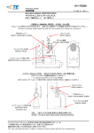
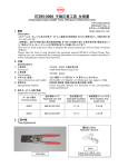
114-5084
Application Specification
取付適用規格
1 Aug 12 Rev D
Crimping of FASTON Receptacles
(ファストン・リセプタクルの圧着条件)
1.
適用範囲
1.
本規格は、.110, .187 及び.250 シリーズファストン・リセ
プタクルの圧着必要条件について規定する。
2.
適用型番及び圧着データ
(1) 連鎖状端子
インスレー
シリーズ
端子型番
ワイヤレンジ
ションレンジ
工具型番 ※1
Scope :
This specification covers the requirements for
crimping of .110, .187 and .250 series FASTON※
receptacles.
2. Applicable Terminal Numbers and Crimp Data
(1) Strip Terminals
クリンプ巾
ワイヤバレル圧着高さ
インスレーショ
Wire Barrel Crimp Height
ンクリンプ巾
±0.05 (mm)
Insulation
Crimp
Terminal
Wire Range
Insulation
Applicator
Series
Width
Numbers
(mm)
Range
Number
Crimp Width
(mm)
(mm)
0.2
0.3
0.5
0.75
1.25
2.0
(mm)
170183-2
0.3~0.75
2.3~3.3
721346-2
2.29
1.24
1.30
1.42
3.30
170096-2
0.3~0.75
2.3~3.3
721346-2
2.29
1.24
1.30
1.42
3.30
170213-□
0.75~2.0
2.54~4.32
721394-2
2.79
1.60
1.70
1.96
4.57
170083-2
0.75~2.0
3.05~4.32
687823-2
3.05
1.55
1.68
1.91
4.57
41274
0.75~2.0
3.05~4.32
687823-2
3.05
1.55
1.68
1.91
4.57
170214-2
0.2~0.5
1.5~2.5
721399-2
1.78
4.8mm
170073-2
0.5~1.25
2.29~3.3
721302-2
2.29
1.14
1.24
1.42
3.56
(.187)
170037-4
0.5~1.25
2.29~3.3
721302-2
2.29
1.14
1.24
1.42
3.56
170037-6
0.5~1.25
2.29~3.3
721302-2
2.29
1.14
1.24
1.42
3.56
2.8mm
170043-2
0.2~0.5
2.0~3.0
720895-2
1.57
0.84
0.91
1.02
2.79
(.110)
170043-4
0.2~0.5
2.0~3.0
720895-2
1.57
0.84
0.91
1.02
2.79
6.3mm
(.250)
0.96
1.02
1.12
3.56
※1 工具型番は AMP-O-LECTRIC オートマシンの型番を記載してある。
※1 Applicator numbers shown above are of those used on AMP-O-LECTRIC crimping machine only.
© Tyco Electronics Japan G.K.,
a TE Connectivity Ltd. Company
All Rights Reserved
タイコ エレクトロニクス ジャパン合同会社
(TE Connectivity Ltd.グループ)
TE logo is a trademark.
*Trademark
This is a Class II confidential document belonging to Tyco Electronics Japan G.K. A Class II
document may not be disclosed to any non-Tyco Electronics persons without (1) the written
approval of a Tyco Electronics manager and (2) the signing of a Confidential Disclosure
Agreement. この文書はタイコ エレクトロニクス ジャパン合同会社に帰属するクラス II 機密文
書です。クラス II 文書は(1)弊社の書面による承認 及び (2)機密保持合意書への署名なしに
社外へ公開することを許可しません。
Other products, logos, and company names might be trademarks of their respective owners.
1 of 5
LOC B
Application Specification
取付適用規格
114-5084
(2) バラ状端子
シリーズ
Series
6.3mm
(.250)
4.8mm
(.187)
2.8mm
(.110)
(2) Loose Piece Terminals
端子型番
Terminal
Numbers
対応連鎖状 端子型番
Strip Terminal
No. Reference
手動工具型番
Hand Tool Number
手動工具
取扱説明書 No.
Instruction Sheet No. of
Hand Tool
170187-2
170095-1
170084-2
41729
170203-2
170038-2
170038-4
170048-2
170048-4
170183-2
170096-2
170083-2
41274
170214-2
170037-2
170037-4
170043-2
170043-4
90166-1
90166-1
755336-1
(注 2) (See Note 2)
720760-1
755336-1
755336-1
720760-1
720760-1
IS-7235
(注 3) (See Note 3)
411-5367
(注 2) (See Note 2)
(注 3) (See Note 3)
411-5367
411-5367
IS-012 J
IS-012 J
(注) 1. バラ状端子の圧着データについては適応手動工具の IS(インストラクション・シート)を参照のこと。
(Note) 1. For details of crimp data, refer to the instruction sheet prepared for the hand tools
respectively.
2. 2 タイプの手動工具が適用
2. Two types of hand tools are available.
手動工具型番
Hand Tool Number
取扱説明書 No.
Instruction Sheet No.
適用電線範囲
Applicable Wire Range
90165-1
755336-1
IS-7235
411-5367
0.75~1.42mm2
1.25~2.27mm2
3. 専用工具でなく他の製品と兼用で使用される手動工具
3. The tool not designed for the terminal listed, but is the nearest equivalent available now.
Rev D
2 of 5
Application Specification
取付適用規格
114-5084
各部の名称
3.
3.
Nomenclature of the Parts
ベンドアップ
ローリング
※ バレル端面から 1.0mm の位置で測定
※ Measure Crimp Height at the point 1.0mm from end of barrel.
ツイスト
ワイヤーバレルのシーム
インシュレーションバレル
ベンドダウン
ワイヤーバレル
電線被覆むき長さ
ベルマウス(後側)
ベルマウス(前側)
電線端末突出し長さ
カット・オフ・タブ
カット・オフ・タブ
インシュレーション圧着高さ
ワイヤーバレル圧着高さ
Rev D
3 of 5
Application Specification
取付適用規格
114-5084
圧着条件及び圧着データ
4.
本規定は連鎖状端子についてのみ適用し、バラ状端子
については本規定を準用し個別に判定する。
番号
No.
1
2
3
4
5
Rev D
項目
Checking Items
カット・オフ・タブ長さ
Cut-Off Tab Length
ベルマウス
前側
Bellmouth
Front
後側
Rear
圧着後の変形量
ベンドアップ
Deviated Forming after Bend-Up
Crimping
ベンドダウン
Bend-Down
ツイスト
Twisting
ローリング
Rolling
芯線端末突出し長さ
Wire-End Protrusion Length
ワイヤバレルシーム
Wire Barrel Seam
4. Crimping Conditions
This specification is applicable to the crimping
processed with the use of automatic crimping
machine only.
However, this specification can be referred to when
judging the workmanship of crimped terminals
processed by hand tools.
圧着条件
Crimping Conditions
0.5mm 以下
0.5mm Max.
0.5mm 以下
0.5mm Max.
0.15~0.65mm 以下
0.15~0.65mm Max.
5°以下
5°Max.
5°以下
5°Max.
5°以下
5°Max.
10°以下
10°Max.
備考
Remarks
0 ~ 2mm
シームは閉じていること。
(但し、開きがある場合芯線の飛び出しがな
いこと。)
Wire barrel seam must be neatly closed.
A slight opening is permissible on
condition that no conductor is outside the
barrel.
4 of 5
Application Specification
取付適用規格
114-5084
適用電線及び圧着部引張強度
5.
本規格において使用する電線は、JIS-C-3306(ビニル・
コード)及び同等品であること。又、0.3mm2 電線につい
ては、JIS-C-2809 に規定する電線相当品であること。
5. Crimping Conditions
The wires to be employed for use under this
specification, shall be conforming or equivalent to
JIS C-3306, Vinyl-insulated Wire. The 0.3 mm2 wire
shall be conforming to JIS C-2809.
導体
圧着部引張強度 (kg 以上)
ビニル絶縁体
Composition of Conductors
厚さ
仕上外径
Vinyl
Outer
2.8mm(.110)
4.8mm(.187)
6.3mm(.250)
Outer
Insulated
Diameter
シリーズ
シリーズ
シリーズ
(mm)
2.8mm(.110)
4.8mm(.187)
6.3mm(.250)
Series
Series
Series
公称断面積
素線数/素線
Cross-
径
外径
sectional
Number of
Area
Strands/Dia
Diameter
Thickness
(Nominal)
meter of a
(mm)
(mm)
2
Crimp Tensile Strength (kg min.)
(mm )
Strand
0.3
12/0.18
0.7
0.8
2.3
5
5
5
0.5
20/0.18
1.0
0.8
2.6
8
8
8
0.75
30/0.18
1.2
0.8
2.8
15
15
1.25
50/0.18
1.5
0.8
3.1
20
20
2.0
37/0.26
1.8
0.8
3.4
Rev D
28
5 of 5