1
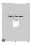
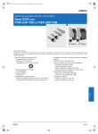
仕様の変更 カタログ・取扱説明書などに記載の商品の仕様および付属品は改善または その他の事由により、必要に応じて、変更する場合があります。当社営業担 当者までご相談のうえ本製品の実際の仕様をご確認ください。 形 F3SX-E 寸法と重量 寸法と重量は名目上の数値ですので、仮に公差を示していても、製造目的 では使用できません。 セーフティコントローラ 取扱説明書 オムロン製品をお買い上げいただきありがとうござい ます。この製品を安全に正しく使用していただくため、 お使いになる前にこの説明書をお読みになり、十分に ご理解ください。また、製品付属の CD-ROM にありま すユーザーズマニュアルもお読みになり、十分にご理 解ください。この説明書とユーザーズマニュアルは、お 読みになった後も、いつもお手元に置いてご利用くだ さい。 誤字・脱字のお断り 本書作成の際には、正確を期すため注意深く検査いたしました。したがって 記載内容に書記、印刷または校正の誤り(誤字、脱字、脱漏)がありましても、 弊社の責任ではありません。 著作権とコピー許可 本書を販売または販売促進するために、許可なくコピー、複製することを禁 じます。 本書は著作権で保護されており、商品と関連した使用に限定しています。そ れ以外では、どのような手段、目的でもコピー、複製される場合は事前に当 社にご連絡ください。またその場合は、一部分ではなく全体をご使用くださ い。 オムロン株式会社 ©OMRON Corporation 2003 All Rights Reserved. 6972444-7C 形 F3SX シリーズの定格やその他の仕様について 形 F3SX シリーズの定格やその他の仕様については、製品に付属して 安全上のご注意 警告 正しい取扱いをしなければ、この危険のために、軽傷・ 中程度の傷害を負ったり、万一の場合には重症や死亡 にいたる恐れがあります。また、同様に重大な物的損 害を受ける恐れがあります。 注意 正しい取扱いをしなければ、この危険のために、時に軽 傷・中程度の傷害を負ったり、あるいは物的損害を受け る恐れがあります。 この製品の設置・配線方法など、お使いになる前に必ずユーザーズマ ニュアルをお読みになり、十分に理解した上でご使用ください。 法規・規格について ●図記号の意味 一般的強制を示します。 非常時に電気的制御で急停止させることが不可能な機械に は、F3SX を使用しないでください。機械の危険部に到達する 前に機械が止まらず、重傷を負う恐れがあります。 ●警告表示 警告 F3SX を分解、修理、改造しないでください。 本来の安全機能が失われ危険です。 ご使用に際してのご承諾事項 F3SX の電源入力に定格以上の DC 電源、または AC 電源を 接続しないでください。また、電源は、逆接しないでください。 製品が故障し、感電の可能性があり危険です。 責任の制限 本製品に関連する特別損害・間接的損害・派生的損害、逸失利益、または 事業上の損失に関しては、この要求が契約責任・保証責任・過失責任また は厳格責任のいずれに基づくものであろうと、当社は責任を負いません。 適合用途の条件 1.本製品を他の商品と組み合わせて使用される場合、お客様が適合すべき 規格・法規または規制をご確認ください。 また、お客様が本製品を使用されるシステム、機械、装置への適合性を決 めるため必要な手順はすべてお客様でご確認ください。 これらお客様用途への本製品の適合性について、当社は責任を負いませ ん。 カタログに記載のアプリケーション事例は参考用ですので、ご採用に際し ては機器・装置の機能や安全性をご確認ください。 2.下記用途に使用される場合、当社営業担当者までご相談のうえ、仕様書 などによりご確認いただくとともに、定格・性能に対し余裕を持った使い方 や、万一故障があっても危険を最小にする安全回路などの安全対策を講 じてください。 a)屋外の用途、潜在的な化学的汚染あるいは電気的妨害を被る用途また は本書に記載のない条件や環境での使用 b)原子力制御設備、焼却設備、鉄道・航空・車両設備、医用機械、娯楽機 械、および行政機関や個別業界の規制に従う設備 c)人命や財産に危険が及びうるシステム・機械・装置 d)ガス、水道、電気の供給システムや 24 時間連続運転システムなど高い 信頼性が必要な設備 e)その他、上記 a)∼d)に準ずる、高度な安全性が必要とされる用途 3.本製品を人命や財産に重大な危険を及ぼすような用途に使用される場合 には、システム全体として危険を知らせたり、冗長設計などで安全性を高 めるよう設計されていること、および本製品が全体の中で意図した用途に 対して適切に配電・設置されていることを必ず事前にご確認ください。 4.本製品が正しく使用されずお客様または第三者に不測の損害が生じるこ とがないよう、使用上の禁止事項および注意事項をすべてご理解のうえで 守ってください。 適用範囲 以上の内容は、日本国内での取引および使用を前提としております。 日本国外での取引および使用に関しては、当社営業担当者までご相談くだ さい。 機械の危険領域との安全距離は、常時確保してください。 安全機能維持のために、24 時間に 1 度は、出力 OFF 状態(非 常停止状態)にしてください。 引火性ガス、爆発ガス雰囲気中では使用しないでください。 内蔵リレーもしくは、外部に接続された電磁開閉器によるア ークなどで発火、爆発を引き起こす可能性があります。 1.保証期間 本製品の保証期間は、ご購入後またはご指定の場所に納入後 1 年といたし ます。 2.保証範囲 上記保証期間中に当社側の責により本製品に故障を生じた場合は、故障部 分の交換または修理を、無償で実施いたします。 ただし、故障の原因が次に該当する場合は、この保証の対象範囲から除外 いたします。 a)本取扱説明書または仕様書などに記載されている以外の条件・環境・ 取扱いならびにご使用による場合 b)本製品以外の原因による場合 c)当社以外による改造または修理による場合 d)本製品本来の使い方以外の使用による場合 e)当社出荷当時の科学・技術の水準では予見できなかった場合 f)その他、天災、災害など当社側の責ではない原因による場合 なお、ここでいう保証は、本製品単体の保証を意味するもので、本製品の故 障により誘発される損害は保証の対象から除かれるものとします。 検出領域を通過せずに機械の危険領域に到達できないよう に、機械周辺に防護構造物を設置してください。機械の危険 領域で作業を行うときは、常に人体の一部を検出できるよう に設置してください。人体が検出されず、重傷を負う恐れがあ ります。 機械の最大停止時間は、実機によって測定してください。ま た、機械の停止時間に変化がないかどうか、定期的に確認し てください。 一般的禁止を示します。 F3SX は、UL から以下の認証を取得しています。 - 米国およびカナダ安全規格に対するリスティング認証 UL508、UL1998、UL61496-1(type4 ESPE)、CSA C22.2 No.14、CSA C22.2 No.0.8 保証内容 二重化安全回路を無効にするような共通原因故障がおこら ないように、十分配慮してください。 リセットスイッチは、危険領域全体が見え、かつ危険領域内 から操作できない位置に設置してください。 F3SX は、EU(欧州連合)機械指令附属書 IV B.安全部品 第 1 項、第 2 項に 該当する製品です。 ①EC 適合宣言 オムロンは、F3SX が以下の EC 指令の要求に適合していることを宣言しま す。 -機械指令 Directive 2006/42/EC -低電圧指令 Directive 2006/95/EC - EMC 指令 Directive 2004/108/EC ②欧州規格 EN61508(SIL1-3)、EN ISO13849-1(Cat.4, PL e)、 EN61496-1(Type4 ESPE)、EN50178、EN55011、EN60204-1、 EN61000-6-2、EN61000-6-4、EN1760、EN574(TypeⅢC)、EN1088 ③国際規格 IEC61508(SIL1-3) 、IEC61496-1(Type4 ESPE)、 IEC60204-1 接続する制御機器は安全機能実現のために、適切なものを 使用してください。 適切な制御機器が使用されない場合、安全機能が低下する ことがあります。 配線を行う際には、F3SX および接続機器の電源を切ってくだ さい。通電中に配線を行いますと、感電する恐れがあります。 また、本装置に接続された外部機器が予期せぬ動作をする 可能性があり危険です。 入出力端子は正しく配線してください。配線を誤ると感電、ま たは安全機能を損なう可能性があります。 ●警告表示の意味 いる CD-ROM のユーザーズマニュアルでご確認ください。 F3SX 単体では、労働安全衛生法第四十四条の二による「型式検定」には申 請できず、システムでの申請が必要となります。したがって、F3SX を日本国 内で同法第四十二条に定められた「プレス機械またはシャーの安全装置」と して使用する場合には、システムで検定を受けていただく必要があります。 F3SX が EN60204-1、IEC61496-1 および UL508 を満たすため に、DC 電源装置は、下記の項目をすべて満たすようにしてく ださい。 • 定格の電源電圧内(DC24V±10%)である。 • F3SX および接続されるセンサ専用とし、他の装置・機器 には接続しない。また、複数の装置に接続する場合は、 各装置の総定格電流に対して余裕をもたせる。 • EMC 指令適合(工業環境) • 1次回路・2 次回路間が 2 重絶縁あるいは強化絶縁 • 過電流保護特性が自動復帰(逆 L 垂下形) • 出力保持時間が 20ms 以上 • UL508 で定義されるクラス 2 回路または制限電圧電流回 路の出力特性要求を満たす。 • 装置が使用される国、地域での EMC と電気機器安全に 関する法律・規格に従う電源である。 (例:EU では EMC 指令、低電圧指令に適合の電源である こと。) 市販のスイッチングレギュレータを使用する場合、FG(フレー ムグランド端子)を接地してください。(接地しないとスイッチン グノイズで誤動作することがあります。) F3SX の通信機能は安全システムを構成する目的で使用しな いでください。配線不良、または上位コンピュータの故障によ り重傷を負う恐れがあります。 補助入力端子(始動命令入力)に安全入力機器を接続する など、安全システムを構成する目的に使用しないでください。 F3SX または周辺機器の故障時に重傷を負う危険がありま す。 補助入力端子(始動命令入力)に、定格電源電圧以上の電 圧を印加しないでください。また、AC 電源を接続しないでくだ さい。製品が故障し、感電の可能性があり危険です。 補助半導体出力は安全出力ではありません。安全システム を構成する目的で使用しないでください。F3SX または周辺機 器の故障時に重傷を負う恐れがあります。 外部表示灯出力は安全出力ではありません。外部表示用途 以外には使用しないでください。 (N モジュール装着形式) DC 半導体安全出力に関して 出力線を DC24V ラインに短絡させないでください。出力が常 時 ON となり危険です。また、出力線の地絡によって出力が ON とならないように、電源の 0V 側を接地してください。 (E モジュール装着形式) F3SX のシングルビームセーフティセンサ入力モジュール(B1 モジュール)は、当社製形 E3FS-10B4□□□(タイプ 2)および 形 E3ZS-T81A(タイプ 2)専用です。絶対に専用外のシングル ビームセーフティセンサを接続しないでください。 (B1 モジュール装着形式) シングルビームセーフティセンサの受光器のモード選択入力 線を 0V に接続すると、しゃ光時 ON(Dark ON) となり、安全シ ステムが構築できません。モード選択入力線は必ず DC24V に接続し、入光時 ON(Light ON) として使用してください。 (B1 モジュール装着形式) 開閉容量(接点電圧、接点電流)などの接点定格値を越える 負荷に対して絶対に使用しないでください。出力回路が破損 し、遮断できなくなる可能性があります。 F3SX を譲渡する際には、必ず本取扱説明書を添付してくださ い。 安全システムの中に本製品を使用する場合、「責任者」が各 国、地方自治体の規格、法規、規制にしたがってください。 F3SX の設置と設置後の確認は、設置される機械について十 分に理解されている「責任者」がお取り扱いください。また、ユ ーザも F3SX を使い始める前に、その設置に関する要件、安 全距離、制御機器、および機能について充分に理解するよう にしてください。 F3SX の保守、点検は、それらが正しく実行されたことを「責任 者」が必ず確認してください。 危険を防止するために、「責任者」は少なくとも 6 ヶ月に 1 回、 F3SX のユーザーズマニュアルに記述されている点検を実施 してください。点検を怠ると、重傷を負う恐れがあります。 F3SX が正しく動作しない場合、ユーザはその旨を「責任者」 に報告し、直ちに機械を停止させてください。 リレー出力に関して、出力接点に直列にヒューズを設置してく ださい。 (リレー出力モジュール装着形式) 複数のセーフティライトカーテン、マルチビームセーフティセン サ、シングルビームセーフティセンサを使用する場合、必ず相 互干渉が発生しないように設置してください。検出不能状態と なり、重傷を負う恐れがあります。 F3SX 用機能設定支援ソフト(F3SX-CD□□□、別売)により F3SX へ設定した内容は、履歴として記録し、保存してくださ い。 (設定可能形式) F3SX 用機能設定支援ソフト(F3SX-CD□□□、別売)により F3SX の設定を変更した後は、必ず「機能テスト」を実施してく ださい。その際、テスト結果は、履歴として記録し、保存してく ださい。 (設定可能形式) DC 半導体安全出力に関して 必ず 2 系統を使用して安全システムを構成してください。1 系 統だけで安全システムを構成した場合、安全機能が損なわ れます。故障時に重傷を負う恐れがあります。 (E モジュール装着形式) DC 半導体安全出力に関して 負荷は出力端子と 0V ラインの間に接続してください(PNP 出 力)。誤って、出力と DC24 V ラインの間に接続すると、非常 停止の時に出力が反転して ON 状態になり危険です。 (E モジュール装着形式) 注意 安全カテゴリは安全システム全体で判定されますので、ご使 用の際には、関連するすべての規格、法規、規制にしたがっ て設計、使用してください。第三者認証機関などに具体的に 相談されることをおすすめします。 リレーの耐久性は、開閉条件、負荷などにより大きく異なりま す。使用にあたっては必ず実使用条件にて実機確認を行い 問題のない開閉回数内にてご使用ください。 F3SX の幅に対して、DIN レールが短い場合など、振動によ り、DIN レールから脱落するおそれがあります。必要に応じ て、エンドプレート(形 PFP-M、別売)を使用し、F3SX を DIN レ ールに固定してください。 F3SX は IP54(IEC60529)以上のエンクロージャー(筐体)内で 使用してください。 安全上の要点 次に示す項目は安全を確保するために必ず守ってください。 (1) 本書をよく読んで十分にご理解の上、正しくご使用ください。 (2) 負荷は、以下の項目のすべてを満たすようにしてください。 ・短絡させない。 ・定格以上の電圧を印加しない。 ・定格以上の電流を流さない。 (3) 感電保護のために F3SX の制御回路(DC24V 回路部分)は、危険電圧か ら、2 重絶縁あるいは、強化絶縁により絶縁してください。 (4) F3SX は、過電圧カテゴリⅡの装置です。過電圧カテゴリⅡの配電系統 に接続してご使用ください。 (5) DC24V 電源の−側は、D 種接地(接地抵抗 100Ω以下)をしてください。 (6) 24 時間に 1 度は、出力 OFF 状態(非常停止状態)にしてください。 (7) F3SX を分解したり、修理、改造しないでください。 (8) 廃棄するときは、産業廃棄物として処理してください。 使用上の注意 製品が動作不能、誤動作、または性能・機能への悪影響を防ぐため、以下 のことを守ってください。 (1) 設置環境について - F3SX を高度 1000m 以上で使用しないでください。 - 次のような場所には設置しないでください。 ・湿度が高く、結露する恐れがある場所 ・品質低下を招く恐れのある煙や微粒子のある場所 ・腐食性ガス、引火性ガス、爆発性ガスのある場所 ・仕様で定められる以上の振動や衝撃が、本体に伝わる場所 ・水、油、薬品がかかる場所 - F3SX の間近で携帯電話やトランシーバー等の強い電磁波を発生させ る機器を使用しないでください。 - 出力に誘導負荷を接続する場合は、サージアブソーバなどで出力回 路を保護してください。 - 通風および配線のために、F3SX の側面に 5mm 以上、上下に 50mm 以 上の空間を確保してください。 (2) 配線・取付けについて - 制御システムは、F3SX の電源を投入後、5 秒以上経過してから作動さ せてください。 - 高圧線や動力線とセンサなどの弱電の入出力線を同一配線管で使用 しないでください。 - コードの金属コネクタを、他のコネクタ(樹脂製コネクタなど)に取り替え る場合、コネクタ内部の導体が IP54 以上で保護される構造としてくださ い。 - すべての端子の信号名を確認し、正しく配線してください。 - 入出力間の配線は、それぞれ 100m 以下で配線して下さい。接続機器 において配線長さが 100m 以下で規定されている場合は、その規定に したがって下さい。 (3) 保守について - シンナー、ベンジン、アセトン類は、清掃に使用しないでください。 (4) 規格に関すること - 安全カテゴリは安全システム全体で判定されますので,ご使用の際に は,関連するすべての規格、法規、規制にしたがって設計、使用してく ださい。第三者認証機関などに具体的に相談されることをおすすめし ます。 - 装置全体の規格の適合についてはお客様の責任において対応願いま す。 (5) 本製品はクラス A 機器です。家庭用環境において、本製品は電波障害 を起こすことがあります。この場合は、責任者が十分な対策を講じてく ださい。 接続する制御機器について 以下の警告表示は、本書の中で使用されているものです。 警告 接続する制御機器は安全機能実現のために、適切なものを 使用してください。適切な制御機器が使用されない場合、安 全機能が低下することがあります。 制御機器 非常停止スイッチ ド ア インタ ー ロック スイッチ 必要事項 直接開路動作接点で IEC/EN60947-5-1 に適合 した第三者認証品を使用してください。ドアイン ターロックスイッチは必要な安全カテゴリを満た したものを使用してください。また、微小負荷 (DC24V、5mA)に適用できるスイッチをご使用く ださい。 両手押しボタンスイ ッチ 1NC/1NO タイプの IEC/EN60947-5-1 適合品を 使用してください。両手押しボタンスイッチの配 置は、EN574 の要求に基づいてください。微小負 荷(DC24V、5mA)に適用できるスイッチをご使用 ください。 ライトカーテン 当社製 形 F3SN/F3SH/F3SJ シリーズを使用し てください。 シングルビーム セーフティセンサ 当社製 形 E3FS-10B4□□□(タイプ 2)または 形 E3ZS-T81A(タイプ 2)を使用してください。 リレー 強制ガイド機構付または EN50205 適合品を使用 してください。強制ガイド機構付でない電磁開閉 器の NC 接点をフィードバック/リセット入力に接 続しても、電磁開閉器の接点の開離不能は発見 できません。第三者認証品を使用してください。 フィードバック用の接点は微小負荷(DC24V、 5mA)に適用できるものを使用してください。 要求する安全カテゴリを満足できるかどうか十 分に検証してからご使用ください。 電磁開閉器 その他の制御機器 通風のために、F3SX の側面に 5mm 以上、上下に 50mm 以上 の空間を確保してください。 電線がより線の場合は、絶縁カバー付き棒型端子 (DIN46228-4 規格適合タイプ)で端末処理をしてから接続して ください。 適合電線(推奨棒端子使用時) :0.34∼1.5mm2 AWG22∼16 コネクタを取付ける際は、指をはさまないように注意してくださ い。 本体の取付け、コードコネクタは確実に締めてください。 F3SX との接続コードは、ピンと張らずに余裕を持たせ、作業 者や物の移動を妨げることが無いように配線されていること を確認してください。 外部表示灯出力に関して 接続する表示灯はフィラメントタイプをご使用ください。LED タ イプ表示灯は完全な故障検知ができません。 (N モジュール装着形式) オムロン株式会社 営業統轄事業部 東京都品川区大崎 1-11-1 ゲートシティ大崎ウエストタワー14F(〒141-0032) ●営業にご用の方も、技術お問い合わせの方も、フリーコールにお電話くだ さい。音声ガイダンスが流れますので、案内に従って操作ください。 0120−919−066(フリーコール) 携帯電話・PHS 等移動通信からのお電話は、お手数ですが、 TEL 055-982-5015(通話料がかかります)へおかけください。 【技術のお問い合わせ時間】 ■営業時間:9:00∼12:00/13:00∼19:00(土・日・祝祭日は 17:00 まで) ■営業日:年末年始を除く 上記フリーコール以外に、055-982-5002(通話料がかかります) におかけいただくことにより、直接センシング機器の技術窓口につながります。 【営業のお問い合わせ時間】 ■営業時間:9:00∼12:00/13:00∼17:30(土・日・祝祭日は休業) ■営業日:土・日・祝祭日/春期・夏期・年末年始休暇を除く ●FAXによるお問い合わせは お客様相談室 FAX:055-982-5051 ●その他のお問い合わせ先 納期・価格・修理・サンプル・承認図は貴社のお取引先、 または貴社担当オムロン営業員にご相談ください。 ■ 定格/性能 (F3SX-E) ■配線例 メインモジュール 項 目 定格・性能 定格電源電圧 電源投入後立ち上がり時間 制御回路の保護 過電圧カテゴリ (IEC60664-1) 絶縁抵抗 耐電圧 DC24V±10% リップル(p-p)10%以下 5 秒以下 出力負荷短絡保護、電源逆接続保護(注 1) Ⅱ リード線一括-ケース外部間 100MΩ以上(DC500V メガにて) リード線一括-ケース外部間 AC2200V 50/60Hz 1min. 動作時:-10~+50℃ (ただし、氷結、結露なきこと。) 保存時:-30~+70℃ (ただし、氷結、結露なきこと。) 動作時・保存時:各 35~85%RH (ただし、氷結、結露なきこと。) 10~55Hz 複振幅 0.7mm X,Y,Z 各方向 20 掃引 (通電) 100m/s2 X,Y,Z 各方向 1,000 回 (通電) ガラス繊維強化ポリアミド 66(PA-66-FR) 端子台:IP20、本体:IP40(IEC60529) 周囲温度 周囲湿度 耐振動 耐衝撃 ケース材質 保護構造 12 22 DC24V E1 A1 T11 T12 T21 T22 Y1 補助出力 安全カテゴリ、パフォーマンスレベル(PL) (EN ISO13849-1) 安全度水準(IEC61508) 定格電流 DC 半導体安全出力(SS1、SS2 端子) 応答時間 安全出力モニタ(AS1 端子) 質量 外形 接続可能な入力機器 Y3 DC24V E1 DC24V PNP トランジスタ出力 負荷電流 300mA 以下(抵抗負荷/誘導負荷)(注 2) 残留電圧(オン時):2V 以下(注 3) 残留電圧(オフ時):0.1V 以下 もれ電流(オフ時):0.1mA 以下 許容容量負荷:1μF 以下 出力端子-負荷間許容配線抵抗:4Ω以下 PNP トランジスタ出力 負荷電流:25mA 以下、残留電圧:2V 以下(注 3) DC 半導体出力 Y2 制御回路 ON :DC15~24V±10% OFF:オープンあるいは、0~DC5V 以下 内部インピーダンス:約 5kΩ 安全出力 (注 1) (注 2) (注 3) 21 DC24V 非常停止入力 リセット入力 フィ-ドバック入力 補助入力 入力 S2 11 S1 0V A2 SSC AS3 AS2 AS1 SS1 SS2 RY1 RY2 FB E1 DC24V カテゴリ 4、PL e SIL3 150mA以下(入出力などの接続機器消費電流を除く) ON→OFF:25ms 以下 OFF→ON:105ms 以下 約 0.2kg(本体のみ) 1 スロット:22.5(W)×111(H)×113(D) 非常停止スイッチ(1ch、2ch 共用) DC24V E1 ヒューズ KM1 本保護機能が作動した場合は、電源再投入にて復帰してください。 誘導負荷には、負荷に並列にダイオードなどのサージアブソーバを接続してください。 コード延長による電圧降下を除く。 RY1 AC KM2 RY2 メインモジュ-ル ■LED 表示 表示 PW 色 緑 名 称 電源表示灯 赤 エラー表示灯 RS 緑 リセット入力表示灯 LK T1 T2 黄 緑 緑 緑 赤 インターロック表示灯 T12 入力表示灯 T22 入力表示灯 安全出力 ON 表示灯 安全出力 OFF 表示灯 EN 通電しているときに点灯します。 エラーが発生したときに、点灯または点滅します。 点灯:非常停止入力間で同期がとれていない 1 回点滅:非常停止入力間が短絡・配線ミス 2 回点滅:非常停止入力回路が故障・配線ミス 3 回点滅:Y1、Y2、Y3 端子の配線ミス・断線 4 回点滅:DC 半導体安全出力の短絡・配線ミス、DC 半導体安全出力回路の故障 5 回点滅:リレー出力モジュールがないので、このエラーは発生しません 6 回点滅:外部機器からのフィードバック信号の異常 常時点滅:ノイズの影響、F3SX 内部回路の故障 次の場合に点灯します。 ・オートリセット時:Y3 端子が入力 ON のとき ・マニュアルリセット時:Y2 端子が入力 ON のとき インターロック状態のときに点灯します。 T12 端子が入力 ON のときに点灯します。 T22 端子が入力 ON のときに点灯します。 安全出力が ON のときに点灯します。 安全出力が OFF のときに点灯します。 KM1 M KM2 S1 :非常停止スイッチ(直接開路動作接点)(形A165E、形A22E) S2 :リセットスイッチ KM1、KM2:マグネット・コンタクタ(形LC1D) RY1、RY2:リレー M :3相モータ E1 :DC24V電源(形S82K) 注1. 上記配線例はカテゴリ4相当になります。 注2. 上記配線例の停止カテゴリ(EN60204-1)は0になります。 信号名 端子名 安全出力モニタ 動作概要 不使用時の配線 AS1 安全出力と同期・同論理の信号を出力します。 オ-プン オ-プン レディ出力 AS2 電源投入後、F3SX の CPU が初期化され、入出力が正常に制御可能な状態 になったときに出力 ON します。ロックアウト時、またはメインモジュ-ルに接 続した非常停止スイッチの押し下げ時に、出力 OFF します。また、スタンバイ 出力と異なり、入力機器のいずれかが OFF した場合も、本出力は OFF となり ます。 AS3 電源投入後、F3SX の CPU が初期化され、入出力が正常に制御可能な状態 になったときに出力 ON します。ロックアウト時、またはメインモジュ-ルに接 続した非常停止スイッチの押し下げ時に、出力 OFF します。 オ-プン スタンバイ出力 フィ-ドバック入力 FB 外部装置の状態を監視するため、外部コンタクタのb接点など、DC 半導体安 全出力と論理が反転した信号を入力します。フィ-ドバック入力信号と、DC 半 導体安全出力が同期しているかを監視しており、同期していない場合、または 監視時間内にフィードバック信号が入力されない場合にロックアウト状態とな ります。 始動命令入力 SSC 上位側からの始動命令を入力します。始動命令入力および接続された入力 機器の両信号が ON の時に安全出力を ON します。 補助出力 ER 機 能 A1端子と直接接続してください ■リセット入力の配線 インターロック機能、リセット入力の配線により設定します。 リセットモード 端子 Y2 接続 DC24V に接続 システムリセットスイッチ (必要な場合のみ NC タ イプのスイッチを配線 する。) DC24V オートリセット Y1/Y3 右図のように接続 Y1 Y3 マニュアル リセット ■リセット 接続図 Y2 ・Y1-Y3 間(オートリセット時)、または Y1-Y2 間(マニュアルリセット時)に接続されたリセットスイッチ を押すことで、F3SX のリセットをかけることができます。 ・マニュアルリセットかオ-トリセットかにより、リセット内容および条件が異なります。(次表参照) ・リセットスイッチを 3 秒以上押下げることにより、システムリセットがかかります。システムリセットによ り、電源を再投入した状態となります。 ・システムリセット入力を受付けるのは、安全出力が OFF している場合です。 ・システムリセットは、ロックアウトを解除するために使用します。 Y3 DC24V に接続 DC24V インターロック/ ロックアウトリセット スイッチ リセットモ-ド F3SX の状態 オ-トリセット時 リセット入力時間(リセット押下時間) 50ms≦入力時間<3s 3s≦入力時間 安全出力 ON 状態 - - ロックアウト時 - システムリセット 安全出力 OFF 状態 (インタ-ロック時) インタ-ロックのリセット システムリセット 安全出力 ON 状態 - - ロックアウト時 - システムリセット Y1/Y2 右図のように接続 Y1 Y2 Y3 マニュアルリセット時 ■エラー表示と対策 F3SXがエラーを検知した場合、ERの表示灯が点灯、または点滅しエラー内容を知らせます。下表に従って対策を実施してください。 ■メインモジュール ER 表示灯の動作 点灯 内 容 原 因 対 策 非常停止スイッチの入力同期エラー 非常停止スイッチの接点不良。 非常停止スイッチとの配線が正しくない。 非常停止スイッチとの配線が正しいか確認する。 非常停止スイッチ入力間の短絡・配線異常 非常停止スイッチの配線がショートした。 非常停止スイッチ、または配線が正しいか確認する。 1 回点滅 非常停止スイッチ入力端子回路の異常 2 回点滅 リセット入力端子の異常 3 回点滅 DC 半導体安全出力端子の異常 4 回点滅 リレー出力端子の異常 非常停止スイッチ入力回路の故障。 F3SX を交換する。 過大なノイズの影響を受けている。 F3SX 周辺のノイズ環境を確認する。 リセット入力端子の配線が正しくない。 リセット入力端子の配線が正しいか確認する。 リセット入力端子の配線が断線、ショートした。 リセット入力端子の配線が正しいか確認する。 リセット入力端子回路の故障。 F3SX を交換する。 負荷(外部機器)の故障。 負荷(外部機器)を交換する。 負荷(外部機器)との配線が正しくない。 負荷(外部機器)との配線が正しいか確認する。 DC 半導体安全出力回路の異常。 F3SX を交換する。 リレー出力モジュールがないので、このエラーは発生しません。 5 回点滅 フィードバック入力端子の異常 6 回点滅 ノイズ、または F3SX の故障 常時点滅 コンタクタなどの外部機器との配線が正しくない。 コンタクタなどの外部機器との配線が正しいか確認する。 コンタクタなどの外部機器の故障。 コンタクタなどの外部機器を交換する。 過大なノイズの影響を受けている。 F3SX 周辺のノイズ環境を確認する。 F3SX の内部回路が故障した。 F3SX を交換する。 Original instructions Model F3SX-E It is our practice to change model numbers when published ratings or features are changed, or when significant construction changes are made. However, some specifications of the products may be changed without any notice. When in doubt, special model numbers may be assigned to fix or establish key specifications for your application on your request. Please consult with your OMRON representative at any time to confirm actual specifications of purchased products. DIMENSIONS AND WEIGHTS Dimensions and weights are nominal and are not to be used for manufacturing purposes, even when tolerances are shown. Safety controller ERRORS AND OMISSIONS INSTRUCTION SHEET The information in this document has been carefully checked and is believed to be accurate; however, no responsibility is assumed for clerical, typographical, or proofreading errors, or omissions. COPYRIGHT AND COPY PERMISSION Please read and understand this instruction sheet before storing, installing, programming, operating, maintaining, or disposing of the products. Please consult your OMRON representative if you have any questions or comments. Please refer to the F3SX User’s Manual for detailed instructions on usage. OMRON EUROPE B.V. (Representative in EU) Wegalaan 67-69. 2132 JD Hoofddorp The NETHERLANDS This document shall not be copied for sales or promotions without permission. This document is protected by copyright and is intended solely for use in conjunction with the product. Please notify us before copying or reproducing this document in any manner, for any other purpose. If copying or transmitting this document to another, please copy or transmit it in its entirety. Precautions on Safety ©OMRON Corporation 2003 All Rights Reserved. ●Meanings of Signal Words WARNING Indicates a potentially hazardous situation which, if not avoided, will result in minor or moderate injury, or may result in serious injury or death. Additionally there may be significant physical damage. CAUTION Indicates a potentially hazardous situation which, if not avoided, will occasionally result in minor or moderate injury, or result in physical damage to property. 6972444-7C Ratings and Specifications For the ratings and specifications of Model F3SX Safety Controller, refer to the F3SX User’s Manual in CD-ROM attached to the product. Please read the User’s Manual and understand the ratings, features, installation procedure, wiring and connection method, etc., before using the F3SX. Legislation and Standards The F3SX alone cannot be applied to the "Type Test" pursuant to the Article 44 of the Industrial Safety and Health Law. It is necessary to apply by the entire system including the controller. Accordingly, in order to use F3SX in Japan as the "Safety device for press machine or shearing tool" pursuant to the Article 42 of the abovementioned law, it is necessary to apply for the test by the entire system. F3SX is the product applicable to European Union (EU) Machinery Directive Annex IV, B, Safety Components, Item 1 and 2. 1) EC Declaration of Conformity OMRON declares that F3SX is in conformity with the requirements of the following EC Directives: -Machinery Directive 2006/42/EC -Low Voltage Directive 2006/95/EC -EMC Directive 2004/108/EC 2) European standardsEN61508 (SIL1-3), EN ISO13849-1(Cat.4 PL e), EN61496-1 (Type4 ESPE), EN50178, EN55011, EN60204-1, EN61000-6-2, EN61000-6-4, EN1760, EN574 (Type IIIC), EN1088 3) International standards IEC61508 (SIL1-3), IEC61496-1 (Type4 ESPE), IEC60204-1 We have obtained the following certificate of UL for F3SX. -Listing certificate for the safety standards of USA and Canada. UL508, UL1998, UL61496-1 (type4 ESPE), CSA C22.2 No.14, CSA C22.2 No.0.8 Suitability for Use WARRANTY OMRON's exclusive warranty is that the products are free from defects in materials and workmanship for a period of one year (or other period if specified) from date of sale by OMRON. OMRON MAKES NO WARRANTY OR REPRESENTATION, EXPRESS OR IMPLIED, REGARDING NON-INFRINGEMENT, MERCHANTABILITY, OR FITNESS FOR PARTICULAR PURPOSE OF THE PRODUCTS. ANY BUYER OR USER ACKNOWLEDGES THAT THE BUYER OR USER ALONE HAS DETERMINED THAT THE PRODUCTS WILL SUITABLY MEET THE REQUIREMENTS OF THEIR INTENDED USE. OMRON DISCLAIMS ALL OTHER WARRANTIES, EXPRESS OR IMPLIED. LIMITATIONS OF LIABILITY OMRON SHALL NOT BE RESPONSIBLE FOR SPECIAL, INDIRECT, OR CONSEQUENTIAL DAMAGES, LOSS OF PROFITS OR COMMERCIAL LOSS IN ANY WAY CONNECTED WITH THE PRODUCTS, WHETHER SUCH CLAIM IS BASED ON CONTRACT, WARRANTY, NEGLIGENCE, OR STRICT LIABILITY. In no event shall the responsibility of OMRON for any act exceed the individual price of the product on which liability is asserted. IN NO EVENT SHALL OMRON BE RESPONSIBLE FOR WARRANTY, REPAIR, OR OTHER CLAIMS REGARDING THE PRODUCTS UNLESS OMRON'S ANALYSIS CONFIRMS THAT THE PRODUCTS WERE PROPERLY HANDLED, STORED, INSTALLED, AND MAINTAINED AND NOT SUBJECT TO CONTAMINATION, ABUSE, MISUSE, OR INAPPROPRIATE MODIFICATION OR REPAIR. SUITABILITY FOR USE OMRON shall not be responsible for conformity with any standards, codes, or regulations that apply to the combination of the product in the customer's application or use of the products. At the customer's request, OMRON will provide applicable third party certification documents identifying ratings and limitations of use that apply to the products. This information by itself is not sufficient for a complete determination of the suitability of the products in combination with the end product, machine, system, or other application or use. The following are some examples of applications for which particular attention must be given. This is not intended to be an exhaustive list of all possible uses of the products, nor is it intended to imply that the uses listed may be suitable for the products: Outdoor use, uses involving potential chemical contamination or electrical interference, or conditions or uses not described in this instruction sheet. Nuclear energy control systems, combustion systems, railroad systems, aviation systems, medical equipment, amusement machines, vehicles, safety equipment, and installations subject to separate industry or government regulations. Systems, machines, and equipment that could present a risk to life or property. Please know and observe all prohibitions of use applicable to the products. NEVER USE THE PRODUCT FOR AN APPLICATION INVOLVING SERIOUS RISK TO LIFE OR PROPERTY WITHOUT ENSURING THAT THE SYSTEM AS A WHOLE HAS BEEN DESIGNED TO ADDRESS THE RISKS, AND THAT THE OMRON PRODUCTS ARE PROPERLY RATED AND INSTALLED FOR THE INTENDED USE WITHIN THE OVERALL EQUIPMENT OR SYSTEM. CHANGE IN SPECIFICATIONS Product specifications and accessories may be changed at any time based on improvements and other reasons. ●Meanings of Alert Symbols Indicates prohibited actions. In order for F3SX to satisfy EN60204-1, IEC61496-1 and UL508, have the DC power unit comply with all of the following requirements. • Voltage within the rated (24V DC ± 10%). • Do not share the power source with other devices or machines. When the power source is shared by multiple devices, consider margins for the total rated current. • Compliant with the EMC Directive, for Industrial environments. • Double or reinforced insulation between the primary and secondary circuits. • Automatic recovery of over-current protection characteristics (voltage drop). • 20ms or over of the output hold time. • Satisfies the output characteristics requirements of a class 2 circuit or equivalent limited energy circuit, as stipulated in UL508. • Compliant with the laws and standards in relation to EMC and other electric device safety in the country or area where this unit is used. (Example: EMC Directive and Low Voltage Directive in EU.) When using a commercialized switching regulator, be sure to ground FG (frame ground terminal). (If not grounded, it may cause erroneous operations due to the switching noises.) Use appropriate control devices to materialize the safety functions. Failure to do so may cause deterioration in the safety performances. Wiring must be done while the power is turned OFF either for F3SX or the devices connected with it. Doing it with the power ON may cause an electric shock. And external devices in connection with this product may behave in an unexpected way. Ensure that the connections are made properly at the input and output terminals. Failure to ensure this may cause an electric shock or damage the safety functions. Ensure that sufficient attention is given so that shared causes of faults do not cause the redundant safety circuit to become ineffective. Set up a protective structure around the applicable machines so that nobody can reach the hazardous area of the machines without passing through the detection zone. If any works should be carried out in such hazardous area, set the sensors that always detect whole or a part of human bodies. Failure to do so causes the detection errors of human body and will lead to a serious injury. Measure the maximum stop time with the actual machine configurations and periodically confirm that the stop time remains unchanged. Never fail to secure the safety distances to the hazardous areas around the machine. Indicates mandatory actions. The reset switch must be installed in a place where the entire dangerous zone can be viewed, and in a way that the switch cannot be operated from the dangerous zone. In order to maintain the safety functions, put the product in the state of output-OFF (the emergency-stop state) once every 24 hours. ●Alert Statements WARNING DO not disassemble, modify, or attempt to repair the F3SX controller. Doing so may damage the original safety functions. DO not operate the F3SX controller in a hazardous environment, such as an environment that contains flammable or explosive gas. Doing so may cause fire or explosion by electric arc generated in the internal relays or externally connected electromagnetic switches. Do not connect the F3SX power input with a DC power supply or AC power supply exceeding the rated voltage. Also do not make reverse connection for the polarity of power supply. Doing either of these may cause breakdown of device and/or danger such as an electric shock. DO not use the F3SX's communication functions for the purpose of configuring a safety system. Doing so may cause serious danger if any trouble occurs with the wiring or programming of the programmable controller. Do not use the auxiliary input terminals (start command input) for connection with a safety input device for the purpose of configuring a safety system. Doing so may cause serious injury to humans when a trouble occurs with F3SX or the peripheral devices. Apply neither of a voltage exceeding the rated nor an AC power supply across the auxiliary input terminals (start command input). Doing either of these may cause breakdown of device and/or danger such as an electric shock. The auxiliary solid-state output (at the AS1,AS2 and AS3 terminals) is not a safety output. Do not use it for the purpose of configuring a safety system. Doing so may cause serious injury to humans when a trouble occurs with F3SX or the peripheral devices. The external indicator output is not a safety output. Do not use it for the purpose other than indication. (N module built in types) Do not use F3SX for the machines that cannot be stopped immediately by the electric control at an emergency. Such machines cannot stop before the human body reaches the hazardous area and will cause a serious injury. With regard to the relay output, install a fuse in serial with the output contacts. (Relay output module built in types) When transferring a F3SX product to another user, be sure to attach this User's Manual. When this product is used in a safety system, a "Responsible Person" must strictly conform to the standards, legislations and regulations of the country and the local government under which the system is operated. A "Responsible Person" who is well aware of and familiar with the machine must implement the installation of the F3SX and confirmation thereafter. And the users must have thorough understanding about the relevant installation requirements, safe distances, control devices and the functions before starting operation. For the inspection and/or maintenance of the F3SX, a "Responsible Person" must confirm that the work has been properly performed. In order to prevent hazardous situation, a "Responsible Person" must implement the inspections according to this User's Manual at least once for every six months. Failure to do so may leads to an accident including a serious injury to humans. Whenever the F3SX does not operate properly, the user shall stop the machine immediately and report it to the "Responsible Person". Please observe the following precautions for safe use of the products. (1) Read this manual thoroughly to understand before using the product. (2) Loads must satisfy all the conditions below: Are not short-circuited. Are not provided with the voltage higher than the rating. Are not used with current higher than the rating. (3) Provide the control circuit (24V DC circuit) of F3SX with double or reinforced insulation for protection from an electric shock. (4) F3SX belongs to the over-voltage category II. Connect F3SX to the power distribution system of the over-voltage category II. (5) Ground the minus terminal of 24V DC for the D-class earthing (through the earthing resistance of 100Ω max.). (6) Put the product in the state of output-OFF (the emergency-stop state) once every 24 hours. (7) Do not disassemble, repair or modify F3SX. (8) Be sure to dispose of the F3SX as industrial waste. Precautions for Correct Use Please observe the following precautions to prevent operation failure, malfunctions, or undesirable effects on product performance. (1) Installation environment: -Do not use F3SX at altitudes over 1,000 meters. -Do not install the F3SX in the following environments: •Areas with high-humidity where condensation is likely to occur; •In the atmosphere with smoke or microparticles which may cause quality deterioration; •In the atmosphere of corrosive, inflammable or explosive gases; •Areas exposed to vibration or shock levels higher than specification provisions; •Areas where the product may come in direct contact with water, oil, chemicals; -Do not use radio equipment, such as cellular phones, walkie-talkies or transceivers which generate radio waves, near the F3SX. -Protect the output circuit with a surge absorber when an inductive load is connected to the output. -For ventilation and wiring, allow for 5mm on both sides of the F3SX, and 50mm or more above and beneath. (2) Wiring and mounting -Do not operate the control system until 5 seconds or more after turning ON the power of the F3SX. -Do not have the input/output lines, such as that for sensor, share the same conduit with the high voltage or power electric lines. -When replacing the metal connectors with other types such as resin connectors, use ones in the structure with the protection grade IP54 or higher. -Wire correctly after confirming the signal names of all the terminals. -Perform wiring between the input and output with a wiring length of 100m or less. When regulations specify that the wiring of a connected device must be 100m or less, perform wiring according to those regulations. (3) Maintenance -When cleaning, avoid using thinner, benzene or acetone. (4) Standards -The safety category is determined by the entire safety control system. Design and use it in accordance with all the related standards. Consultation with an independent certification organization is recommended. -The customer is requested to make compliant with the applicable standards for the entire system. (5) This is a class A product. In residential areas it may cause radio interference. in which case the Responsible Person may be required to take adequate measures to reduce interference. Control Devices to Be Connected The following signal words are used in this instruction sheet. Be sure to align the devices so as to prevent mutual interference when using multiple safety light curtains, multi-beam safety sensors or single-beam safety sensors. Failure to do so may cause non-detectable conditions and a serious injury to humans. Regarding setting to F3SX by using the function set-up software for model F3SX (Model F3SXCD□□□, sold separately), keep the set contents in the history. (Configurable types) After changing any settings to F3SX by using the function set-up software for model F3SX (Model F3SXCD□□□, sold separately), be sure to carry out the "Function test" and keep the test results in the history. (Configurable types) DC solid-state safety output; Be sure to configure the safety system by using two channels. Only with one channel to be used, the safety functions of the system will be degraded. It may cause serious injury to humans when a trouble occurs. (E module built in types) DC solid-state safety output; Connect a load across the output terminal and the 0V line (PNP output). If it is connected between the output terminal and the 24V DC line by mistake, the output may turn ON when an emergency-stop occurs and cause a dangerous situation. (E module built in types) CAUTION DC solid state safety output; Do not short-circuit the output lines to the 24V DC line. Doing so will make the output always ON and dangerous. Also, ground the 0V line of the power source so that the output does not become ON when the output line is grounded. (E module built in types) The single-beam safety sensor input module (B1 module) of F3SX is for the exclusive use with the OMRON Model E3FS-10B4□□□(Type 2) and E3ZS-T81A(Type 2). Be sure to avoid connecting the module to the single-beam safety sensor other than the specified for the exclusive use. (B1 module built in types) If the mode selection input line of the single-beam safety sensor receiver is connected to 0V, the output turns ON when light is interrupted (Dark ON), which no longer configures the safety system. Ensure connection of the mode selection input line to 24V DC to make the sensor output ON when light is incident (Light ON). (B1 module built in types) Never use with a load in excess of the trip capacity (contact voltage, contact current). Doing so may damage the output circuit and cutoff may not be possible. Precautions for Safe Use The safety category is determined by the entire safety control system. Design and use it in accordance with all the related standards. Consultation with an independent certification organization is recommended. The life duration of the relays varies depending on the switching conditions or loads, etc. Use the relays within an appropriate switching times, after confirming the limit of switching times with the actual devices under the actual conditions. If the DIN rail is too short for the width of F3SX, the product may drop out of the rail by vibration. Use end plate (Model PFP-M, sold separately), to fix F3SX on the DIN rail where necessary. Use F3SX in an enclosure rated at least IP54 (IEC60529). WARNING In order to maintain the total safety functions, use appropriate device for connection with the product. Failure to do so may cause degradation of the safety functions. Control device Requirements Emergency-stop switch Use the switch of positive opening operation complying with IEC/EN60947-5-1. Also, use the parts having been approved by the certification body. Use the door interlock switch satisfying the required safety category. Use the switch compatible with the load of small current (24V DC, 5mA). Door interlock switch Two-hand control switch Use switch of 1NC/1NO type complying with IEC/EN60947-5-1. Place two-hand control switch according to the requirements of EN574. Use the switch compatible with the load of small current (24V DC, 5mA). Light curtain Use OMRON Model F3SN/F3SH/F3SJ series manufactured. Single-beam safety sensor Use OMRON Model E3FS-10B4□□□(Type 2), E3ZS-T81A(Type 2). Relay Use those with forcibly guided (linked) contacts or those conforming to EN50205. If connecting the NC contact of an electromagnetic breaker without the forcibly guided (linked) contacts to the feedback/reset input line, inability in declinator contact of such electromagnetic breaker cannot be found out. Use those having been approved by the certification body. The feedback contacts should be compatible with the load of small current (24V DC, 5mA). Electromagnetic breaker Other control devices Use upon confirming that each of those satisfies the required safety category. For ventilation, allow for 5mm or more on both sides of the F3SX and 50mm or more above and beneath. Stranded wire should be processed with insulation-covered bar terminal (DIN46228-4 standard compatible type) at its ends before using for connection. Conforming wire (when using recommended bar 2 terminals): 0.34 to 1.5mm AWG22 to 16 Be careful not to catch a finger in the connector when installing it. Connect firmly at the time of main body mounting and connect the cable connectors. Allow some leeway for the wires and do not tighten the wires when wiring connection cables to F3SX, and confirm that any cable may not block the movements of workers or objects. For the external indicator, use a filament-type lamp for the externally connected indicator. With an LED type indicator, the perfect detection of a trouble is not available. (N module built in types) OMRON Corporation Shiokoji Horikawa, Shimogyo-ku, Kyoto, 600-8530 JAPAN Tel:(81)75-344-7093 / Fax:(81)75-344-8197 OMRON EUROPE B.V Wegalaan 67-69, NL-2132 JD Hoofddorp THE NETHERLANDS Tel: (31)-2356-81-300 / FAX: (31)-2356-81-388 Example of wiring Rating and Performance Main Module (F3SX-E) Item Rated power voltage Rise time at turning power on Protection for control circuit Over-voltage category (IEC60664-1) Insulation resistance Withstand voltage Ambient temperature Ambient humidity Vibration resistance Shock resistance Enclosure materials Protection structure Emergency-stop input Reset input Input Feedback input Auxiliary input DC semiconductor output Rating and Performance DC24V±10% with ripple (p-p) of 10% or less 5 seconds or less Protection from short-circuiting of output load, and protection from reverse connection of power supply. (Note 1) II Collective lead wire from all terminals - external enclosure: 100MΩ or more (by DC500V megger) Collective lead wire from all terminals - external enclosure: AC2200V, 50/60Hz for 1 min.. Operating: -10 to +50℃ (not freezing or condensation) Storage: -30 to +70℃ (not freezing or condensation) Operating and storage: 35 to 85%RH each (not freezing or condensation) 10 to 55Hz double amplitude of 0.7mm each in X, Y and Z direction, 20 sweeps (with power on) 2 100m/s each in X, Y and Z direction, 1,000 times (with power on) Glass fiber reinforced polyamide 66 (PA-66-FR) Terminal block: IP20, Main body: IP40 (IEC60529) ONF : DC15 to 24V±10% OFF : Open or 0 to DC5V Internal impedance: Approximately 5kΩ S2 Auxiliary output 12 22 DC24V E1 A1 T11 T12 T21 T22 Y1 Y2 Y3 Control circuit DC24V DC24V COM E1 DC24V 0V A2 SSC AS3 AS2 AS1 SS1 SS2 RY1 RY2 FB E1 PNP transistor output Load current : 25mA max , Residual voltage : 2V max (Note 3) Category, Performance level (PL) (EN ISO13849-1) Safety integrity level (IEC61508) Rated current DC semiconductor safety output Response (SS1, SS2 terminal) time Safety output monitor (AS1 terminal) Weight External shape Connectable input devices 21 S1 PNP transistor output Load current 300mA max (resistive load/inductive load) (Note 2) Residual voltage (for ON) : 2V max (Note 3) Residual voltage (for OFF) : 0.1V max Leakage current (for OFF) : 0.1mA max Permissible capacity load : 1 µF max Allowable wiring resistance between output terminal and load : 4Ωmax Safety output 11 DC24V Cat.4, PL e SIL3 150mA or less (except current consumption for the connected input/output devices) ON→OFF : 25ms or less OFF→ON : 105ms or less DC24V Approximately 0.2kg (main body only) 1 slot : 22.5(W)×111(H)×113(D) Emergency-stop switch (common to Ch.1 and Ch.2) E1 Fuses (Note 1) When this protection function operates, recover by turning the main power ON again. (Note 2) Insert a surge absorber such as diode in parallel to the inductive load. (Note 3) Not including voltage drops in the extended wire. KM1 RY1 AC Main Module KM2 RY2 LED Indicator Indication PW Color Green ER Red Name Power indicator Error indicator RS Green Reset input indicator LK T1 T2 Yellow Green Green Green Red Interlock indicator T12 input indicator T22 input indicator Safety output ON indicator Safety output OFF indicator EN Functions Lights up while power is ON. Lights up or flashes when an error occurs. Lighting up :No synchronization between emergency-stop inputs. 1-time flashing :Short-circuiting or mis-wiring between emergency-stop inputs. 2-time flashing :Trouble or mis-wiring around emergency-stop input circuit. 3-time flashing :Mis-wiring or break around Y1, Y2 or Y3 terminal. 4-time flashing :Trouble in DC semiconductor safety output or around the circuit for DC semiconductor safety output. 5-time flashing :This error does not occur because there is no relay output module. 6-time flashing :Error in feedback signals from an external devices. Continuously flashing :Affected by noises or trouble around the internal circuit of F3SX. Lights up at the time of: • Auto resetting:Y3 terminal input is ON. • Manual resetting:Y2 terminal input is ON. Lights up in interlock states. Lights up when input is ON at T12 terminal. Lights up when input is ON at T22 terminal. Lights up when safety output is ON. Lights up when safety output is OFF. KM1 M KM2 S1 :Emergency-stop switch (positive opening contacts) (Model A165E, Model A22E) S2 :Reset switch KM1、KM2:Magnetic contactor (Model LC1D) RY1、RY2:Relay M :3 phase motor E1 :DC24V power source (Model S82K) Note 1 :Example of wiring above corresponds to the Category 4. Note 2 :Example of wiring above corresponds to the Stop Category (EN60204-1) 0. Terminal name Signal name Auxiliary output Safety output monitor AS1 Ready output AS2 Standby output AS3 Feedback input FB Start command input SSC Operations Wiring when not used Outputs signal that is synchronous and in the same logics as those of the safety output. When F3SX CPU has been initialized and the input and output have turned into normally controllable state, the output is turning ON. The output is OFF when the emergency-stop switch, connected to the main module, is pressed or the F3SX is lock-out. This output is also turning OFF unlike a Standby output when either of input apparatus turns OFF. When F3SX CPU has been initialized and the input and output have turned into normally controllable state, the output is turning ON. The output is OFF when the emergency-stop switch, connected to the main module, is pressed or the F3SX is lock-out. In order to monitor the status of external devices, feeds back the input signal that is logically reversal to the DC semiconductor safety output, such as the NC contact of the external contactor. Meanwhile monitoring whether the feedback input signal and DC semiconductor safety output are synchronous, the device is brought in the lock-out state when they do not synchronize or the feedback signal is not input during the monitoring time. Inputs the start command received from the host side. Turns the safety output ON when the start command input and input signal of the connected device are both ON. Open Open Open Connect directly to the A1 terminal. Wiring for reset inputs Reset Interlock functions are set by the reset inputs wiring. TerReset mode Connection Schematic diagram minal Y2 Connect to DC24V System reset switch ( NC type switch to be used when necessary.) DC24V Auto reset Y1/Y3 See right figure Y3 Connect to DC24V Y1 Y2 Y3 DC24V Manual reset Y1/Y2 - F3SX can be reset by pressing the reset switch connected between Y1 and Y3 (for auto reset) or Y1 and Y2 (for manual reset). - The details and conditions of reset vary depending on whether it is manual reset or auto reset. - Pressing the reset switch for 3 seconds or longer enables the system reset. By system reset, it will be in the state where the power supply was re-switched on. - The system-reset input can be accepted in which the safety output is OFF. - System reset is used in order to cancel a lock-out. Interlock / Lock-out reset switch Time duration of reset input (while reset switch is pressed) Reset mode State of F3SX 50ms ≤ input time < 3s 3s ≤ input time Auto reset Safety output ON state - - At lock-out - System-reset Reset of interlock System-reset - - - System-reset See right figure Y1 Y2 Y3 Manual reset Safety output OFF state Safety output ON state At lock-out Error indications and measures to be taken When F3SX detects an error, indicator of ER lights up, or flashes to notify the error contents. Take appropriate measures according to the table below. Main module ER indication Lighting up 1-time flashing 2-time flashing Error Synchronization error of emergency-stop switch inputs. Short-circuiting or wiring error among emergency- stop switch inputs. Error around circuit of emergency-stop switch terminal. Error around reset input terminal. 3-time flashing 4-time flashing Error around DC semiconductor safety output terminal. Assumed causes Defects in emergency-stop switch contacts. Or improper wiring with emergency-stop switch. Measures to be taken Confirm emergency-stop switch or its wiring. Short-circuiting around emergency- stop switch wiring. Confirm wiring with emergency-stop switch. Trouble with emergency-stop switch input circuit. Replace F3SX. Affected by noises of excess level. Confirm noise environment surrounding F3SX. Improper wiring with reset input terminal. Short-circuiting or wire break around reset input terminal. Trouble with reset input terminal circuit. Trouble with the load (external device). Improper wiring with the load (external device). Trouble with DC semiconductor safety output circuit. Confirm wiring with reset input terminal. Confirm wiring with reset input terminal. Replace F3SX. Replace the load (external device). Confirm wiring with the load (external device). Replace F3SX. Error around relay output terminal. This error does not occur because there is no relay output module. Error around feedback input terminal. Improper wiring with external device such as contactor. Trouble with external device such as contactor. 5-time flashing 6-time flashing Continuously flashing Disturbance by noises or trouble with F3SX. Confirm wiring with external device such as contactor. Replace the external device such as contactor. Affected by noises of excess level. Confirm noise environment surrounding F3SX. Trouble with F3SX internal circuit. Replace F3SX.