1
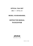
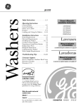
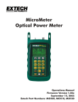
Optical Light Source
ミニ光源
MODEL
351/352/362/363/372/373
Instruction Manual
取扱説明書
HR1071-13J-12/100701
Instruction manual
IMPORTANT SAFETY INSTRUCTIONS ...........................................................................1
1. SPECIAL FEATURES..............................................................................................................2
2. CONFIGURATION.....................................................................................................................2
3. OPERATION INSTRUCTION................................................................................................3
3-1 DESCRIPTIONS OF PARTS ..................................................................................................3
3-2 OPERATION OF UNIT...........................................................................................................5
3-3 BATTERY REPLACEMENT ..................................................................................................6
4. CLEANING THE OUTPUT PORT........................................................................................7
5. SPECIFICATIONS......................................................................................................................7
5-1 SPECIFICATIONS BY MODEL ..............................................................................................7
5-2 GENERAL ..............................................................................................................................8
6. OPTION..........................................................................................................................................8
7. AFTER-SALES SERVICE INFORMATION.....................................................................9
目次
製品を安全に使用するための注意事項 ...............................................................................10
1. 特長.................................................................................................................................................11
2. 構成.................................................................................................................................................11
3. 操作方法........................................................................................................................................12
3-1 各部の説明........................................................................................................................12
3-2 使用方法.............................................................................................................................13
3-3 電池の交換........................................................................................................................14
4. 光出力部の清掃方法.................................................................................................................14
5. 規格.................................................................................................................................................15
5-1 仕様......................................................................................................................................15
5-2 共通仕様.............................................................................................................................15
6. オプション.....................................................................................................................................16
7. アフターサービス.......................................................................................................................16
IMPORTANT SAFETY INSTRUCTIONS
Before use, read the following safety instructions.
CAUTION:CAUTION to avoid hazards which may cause human injury or
may damage the instrument.
1. Warning for laser light
(1). These laser light product outputs “Laser Class1” light, which does not
damage human eyes.
However, if you gaze at the laser light intentionally, even a “Laser
Class1” laser may injure your eyes.
(2). Do not look into the ferrule face of the output port, or this can be
damaging your eyes.
(3). Do not point the output port at a person.
2. Cautions for a proper use
(1). Static electricity may damage the unit. Before use, discharge the static
electricity of the body by touching the metal of the building or other
object.
(2). Excessive ambient noise may affect the unit's normal operation.
If the unit is not working properly, turn it off and start operations again
from the beginning.
(3). The light emitting section of the output port must be kept clean and
free of dust and dirt at all times. Take particular caution when
removing and fitting the connectors and adapters. Be sure to use the
protection cap or case when the unit is not in use
For information regarding cleaning the output port, refer to “4.
Cleaning the output port”.
(4). Do not drop or swing the unit by the strap.
(5). Remove the battery when you will not use the unit for a long time.
-1-
1. Special features
(1). A light-weight pocket MINI Light Source designed to measure optical
power as well as fiber identification in fiber optics communication.
(2). The unit is equipped with a LED light source with wavelengths of
either 850nm or 1310nm and a LD light source with wavelengths of
either 1310nm or 1550nm.
(3). A unit that can be connected to various attachments through use of
the appropriate connector adapter.
(4). Auto power off function. (10 minutes)
(5). Small and attractively designed covering case that protects the
output port and operation buttons, suitable to be carried in one’s
pocket or a tool box.
2. Configuration
The Light Source consists of the main body and connector adapters
accommodating various fiber connectors;
FC connector
180-FC
ST connector
180-ST
SC connector
180-SC
FC connector
181-FC
ST connector
181-ST
SC connector
181-SC
LED Light source
LD Light source
-2-
3. Operation instruction
3-1 Descriptions of parts
③
⑥
④-2
②
①
④-1
⑤
① ON/OFF Button
This button activates the operation of the unit. Turn the unit off by
pushing the button while the unit is in operation.
To override the auto-off continue to press the ON/OFF button for
approximately 3 seconds when activating the unit, until the Power
LED (④-1) begins to blink.
② MOD Button
Each time the button is pressed, the modulation frequency of CW
(continuous wave) and CHOP wave changes as follows.
→ CW → 270Hz → 1kHz → 2kHz →
The selected modulation frequency is saved, and it is used when the
unit is turned ON next time.
In order to cancel “MOD” selection, and return the unit to its initial
settings, hold down both the ON/OFF button and the MOD button for
approximately 2 seconds when activating the unit.
The initial setting is CW (continuous wave).
-3-
③ Output port
This port is where the laser power enters the fiber optics.
The interchangeable adapters are to be attached here. This port
accommodates a wide variety of connector types.
The 180-** type connector adapter is designed for use with the LED
light source(Model 351, 352)
The 181-** type connector adapter is designed for use with the LD
light source(Model 362, 363, 372, 373)
④ LED Display
④-1 Power LED
This LED shows that light is being emitted.
A blinking light indicates low battery power.
④-2 MOD LED
The selected frequency is shown by MOD Display LED.
⑤ Battery Compartment
The battery is to be installed here.
⑥
Strap hole
The strap is to be put on here.
⑦ Case
The case is used to protect the output port, the operation buttons,
and the LED display when the unit is not in use. It is not necessary
to remove the connector adapter when covering the unit with this
case.
-4-
3-2 Operation of Unit
Rear side
(1) Battery
Slide the battery cover off and insert one AA
battery in the direction of the polarity mark
as indicated in the battery compartment.
AA Battery
Cover
(2) Case
Slide the case off and insert the unit into the case from the opposite
direction.
Remove case
⑦ Case
Insert oppositely
(3) Power
Activate the unit by pressing the ON/OFF button.
(4) The MOD Selection
Press the MOD select button to set the modulation frequency.
(5) Connector adapter
Tightly attach the connector adapter to the output port.
Tighten the adapter's screw while pressing the sleeve in to move
the pin into the guide hole. (181-** connector adapter)
Optical Fiber
Optical Connector
Connector adapter
Strap hole
Light source port
-5-
(6) Measurement
For measurement purposes, attach the optical fiber connector to
the connector adapter. To get an accurate measurement, be sure to
maintain the physical configuration of the fiber throughout the time
of measurement.
Tighten the connectors securely. The ferrule face should be kept in
a clean environment away from dust at all times.
The LD light source may be unstable because of the backreflection.
Please connect an APC ferrule to the Optical Power Meter side to
prevent it.
〔Reference〕
Connect two reference cables to the Light Sourece and measure output
at that time. P1(dBm)
Reference cable A
LD Light source
Reference cable B
Optical Power Meter
APC ferrule
P1 (dBm)
〔Measurement〕
Connect the measuring fiber between reference cables and measure
output at that time. P2(dBm)
The measuring fiber
Reference cable A
LD Light source
Reference cable B
Optical Power Meter
APC ferrule
P2 (dBm)
The insertion loss of the measuring fiber (dB)
=P2 (dBm)-P1 (dBm)
3-3 Battery replacement
The blinking of the Power LED indicates that the battery is low and
needs replacing.
-6-
4. Cleaning the output port
Because the path traveled by light, at the PC polished output port, is
extremely small, any dust on the ferrule face not only disrupts
connection with the fiber, but also leads to greater coupling loss and
reflection. Dust can also damage the ferrule.
The output ports are cleaned as follows.
【 When the connector adapter is attached 】
a. Remove dust from the ferrule face with a 2.5 mm CLETOP stick
or comparable product.
【 When the connector adapter is removed 】
a. Wipe the ferrule face with a swab dipped in ethanol or
isopropanol.
b. Wipe the ferrule face with a dry swab once again.
c. Blow on the ferrule face with clean air.
5. Specifications
5-1 Specifications by model
Model
Element
Wavelength
351
352
850
±30nm
Applicable fiber
Output level (CW)
Spectral width
Stability
Short-term stability
Power consumption
(CW. Approx.)
Battery life (Approx.
with alkaline battery)
362
363
LED
372
LD
373
LD(DFB)
1310
1310
1550
±30nm
±30nm
±30nm
1310
1550
±20nm
±20nm
APF, PCF, GI
SM
>-25dBm*1 >-30dBm*1
>-5dBm
≦60nm
≦150nm
≦5nm
≦1nm
(FWHM)
(FWHM)
(RMS)
(⊿λ, -20dB)
<0.4dB *2
<0.4dB *2
3
<0.05dB *3
<0.02dB *
140mW
90mW
90mW
140mW
140mW
140mW
18hrs.
30hrs.
30hrs.
18hrs.
18hrs.
18hrs.
Internal modulation
CW, 2KHz, 1KHz, 270Hz
SC standard
(180-SC)
*1 : GI50/125 *2 : At 0℃ to 40℃(12-hour)
3
* : At 0℃ to 40℃ (1-hour, uniform temp.)
Optical connector
-7-
SC standard (181-SC)
5-2 General
Auto off
Low Battery
Memory Function
Storage temperature
Automatically turned off 10 minutes after the final
key operation
Power LED blinking
When the power is turned off, the state of the
modulation frequency is preserved.
-20 ゚C to 60 ゚C
-10 ゚C to 50 ゚C(80%RH or less, non condensing)
UM-3 (AA) battery X 1pc
Power supply
(Manganese, Alkaline, NiMH)
Main unit
61 (W)× 99 (H)× 22 (D) mm
Outer
dimension
With case
65 (W)× 120 (H)× 24 (D) mm
Weight
Approx. 130g (including case and battery)
・UM-3(AA) battery
1
・Case
1
Accessories
・Instruction manual
1
・Strap
1
・SC Connector adapter
1
Specifications are subject to change without notice.
Operation temperature
6. Option
Name
Connector
Adapter
Model No.
180-SC
180-FC
180-ST
180-DIN
180-SMA
180-BC
180-SBC
180-MBNC
180-SMA/DIA
181-SC
181-FC
181-ST
181-DIN
181-SMA/DIA
NTT
NTT
AT&T
DIAMOND
ANPHENOL
AT&T
AT&T
SUMITOMO
DIAMOND
NTT
NTT
AT&T
DIAMOND
DIAMOND
-8-
Remarks
SC
FC
ST
DIN
SMA,906/905
BICONIC
SMALL BICONIC
MINI BNC
MMS-10/A
SC
FC
ST
MMS10/A
7. After-sales service information
When making requests for repair service, please bring the instrument
directly to the dealer. If this is impossible, however, send the
instrument directly to our sales office in Tokyo, Japan.
To ensure speedy and reliable repair, always include information as to
the type of failure and cause. Return accessories with the instrument if
required.
Warranty
Graytechnos Co., Ltd. warrants this product to be free from defects in
material and/or workmanship for one full year from date of shipment.
During the warranty period, we will , at our option, repair or replace any
product which proves to be defective.
For warranty service, send the product prepaid to the distributor or
Graytechnos Head Office in Tokyo, Japan. The repaired product will
be returned prepaid to Buyer.
Limitation of Warranty
This warranty shall not apply to defects resulting from any misuse,
misapplication, unauthorized modification, improper maintenance or
operation or storage outside of the environmental specifications.
Graytechnos makes no other warranties, expressed or implied, including
without limitation thereof, any implied warranty of merchantability or
fitness for a particular purpose.
Graytechnos shall not be responsible for any direct, indirect , special,
incidental or consequential damages.
Graytechnos Co.,Ltd.
Kojima-build 2F, Ueno 1-6-5, Taito-ku, Tokyo, 110-0005 Japan
Phone:+81-3-5807-6081 Fax:+81-3-5807-6082
email:[email protected]
-9-
製品を安全に使用するための注意事項
製品を御使用する前に必ずお読み下さい。
注意: この表示の内容を守らない場合、人体に傷害を及ぼすか本器の
性能を損なう可能性があります。
1. レーザ光源についての注意
(1). 当製品は、発光されているレーザ光を誤って見ても、目への障害が少ない
クラス 1 です。
しかし、意図的に光源から発光されている光を直視し続けると、目の損傷お
よび失明する危険があります。
(2). 光ファイバを直接、覗き込まないで下さい。
目を損傷および失明する危険があります。
(3). 発光部を人へ向けないで下さい。
2. 製品取扱上の注意
(1). 静電気により製品が損傷する可能性があります。製品を取り扱う前は金属
製のものに触れるなどして、人体の静電気を取り除いて下さい。
(2). 外部からの過大なノイズ等で正常動作しなくなる事があります。その場合は
電源を入れ直して下さい。
(3). 光出力部はホコリ等によって性能が著しく悪化しますので、光コネクタの脱
着時にホコリが付着しない様に充分に注意して下さい。
使用しない時は必ず保護キャップや本体カバーを取り付けて下さい。
光出力部の清掃については、「4. 光出力部の清掃方法」を参照して下さ
い。
(4). 製品を落したり、振り回したりしないで下さい。
(5). 長期間使用しない場合は、乾電池を取り外して保管して下さい。
- 10 -
1. 特長
(1). 光ファイバを使用した光通信で光減衰特性などを測定するための軽量
ポケットサイズの「ミニ」光源です。
(2). 光源波長は、LED 光源が 850, 1310 nm、LD 光源が 1310 ,1550nm を
それぞれ用意しています。
(3). 先端のアダプタの交換で、各種のコネクタと接続可能です。
(4). オートパワーオフ機能により、電源切り忘れを防止します。
(5). 使用時以外は、カバーにより、光出力部及び表示操作部が保護されま
すから、そのままポケットや工具箱に収納できます。
2. 構成
本体と、本体に内蔵された光源部、そして各種の光ファイバに対応するため
のアダプタ部(別売)により構成されます。
FC コネクタ
アダプタ FC
ST コネクタ
アダプタ ST
LED 光源
SC コネクタ
アダプタ SC
各種コネクタアダプタ
FC コネクタ
アダプタ FC
ST コネクタ
アダプタ ST
LD 光源
SC コネクタ
アダプタ SC
- 11 -
3. 操作方法
3-1 各部の説明
①ON/OFF ボタン
⑥
ON/OFF を押すと電源が入り測定が
で き ま す 。 電 源 が 入 っ た 状 態 で ④-2
ON/OFF を押すと、電源が切れま ②
す。
①
オートパワーオフ機能を解除するには
電源を入れるとき、ON/OFF を 3 秒
以上(④-1 LED 点灯が点滅に変わ
まで)押します。
③
④-1
⑤
る
初期設定にするには、ON/OFF と MOD を同時に 2 秒以上押します。
初期設定は CW(直流)です。
②MOD ボタン
MOD を押すごとに変調周波数が切り換わります。変調周波数は表示
LED④-2 で表示されます。
変調周波数の設定は保存され、次回電源 ON する時にその設定が反映さ
れます。
③光出力部
光パワーを出力する光学的接続部です。コネクタアダプタを取り付けます。
LED 光源(Model 351、352)の場合には、180-**タイプのコネクタアダ
プタを取り付けて下さい。
LD 光源(Model 362,363,372,373)の場合には、181-**タイプのコネク
タアダプタを取り付けて下さい。
④表示 LED
1). 電源表示 LED:光源が発光していることを示します。また、電池電圧
が低下しますと点滅します。
2). MOD表示 LED:光源の出力状態を示します。
- 12 -
⑤電池収納部
電池を収納する所です。
⑥ストラップ取付穴
ストラップを取付ける穴です。
⑦カバー
本体を使用しないときに光出力部や操作部および表示 LED を保護するた
めのカバーです。
3-2 使用方法
(1) 電池蓋を下方にスライドさせ、電池ケースに単 3 電池
1 本を内部の極性マークに従って充填します。
(2) カバーを取り外し、裏側に取り付けます。
本器裏面
単三乾電池
カバーを取り外す
電池蓋
⑦カバー
カバーを裏側に取付ける
(3) ON/OFF を押し、電源を ON にします。
(4) MOD で変調周波数を選定します。
(5) 使用するファイバに適合するコネクタアダプタをしっかりと取り付けます。
光ファイバ
光コネクタ
コネクタアダプタ
ストラップ取付穴
出力部
- 13 -
(6) コネクタアダプタに、測定する光ファイバのコネクタを接続します。
光ファイバ接続後は、ファイバの状態を同一にたもち、コネクタは確実に
締め付けて下さい。又、フェルール端面にゴミ等が付着しないよう常に御
注意下さい。ファイバの反射により LD 光源出力が不安定になることがあ
ります。それを防ぐには、光パワーメータ側を斜め PC 研磨コネクタにする
ことが有効です。
〔基準値〕
光源にリファレンスケーブル 2 本を接続し、その時の光パワーを測定しま
す。 P1(dBm)
A
リファレンスケーブル
LD 光源
リファレンスケーブル B
光パワーメータ
APC フェルール
P1 (dBm)
〔測定〕
測定する被測定ファイバをリファレンスケーブル間に入れ、その時の光
パワーを測定します。 P2(dBm)
リファレンスケーブル A 被測定ファイバ
LD 光源
リファレンスケーブル B
光パワーメータ
APC フェルール
被測定ファイバの損失 (dB) = P2 (dBm) - P1 (dBm)
P2 (dBm)
3-3 電池の交換
御使用中に電源表示 LED が点滅した場合は、速やかに新しい電池と交
換して下さい。
4. 光出力部の清掃方法
光出力部のフェルールは PC 研磨端面で、光の通る径が非常に小さいため、
汚れやほこりがあると光ファイバと正しく接続することができなくなり、接続損
失や反射が多くなります。また、ほこりによる損傷を受けることもあります。
光出力部の清掃は下記に従って下さい。
【コネクタアダプタを取り付けた状態のとき】
a. 市 販 の ス リ ー ブ 内 清 掃 用 具 ( ス テ ィ ッ ク タ イ プ /CLETOP 、
OPTIPOP S 等)で清掃して下さい。
【コネクタアダプタを取り外した状態のとき】
a. エタノールやイソプロパノールをしみこませた綿棒等で光ファイ
バの端面を拭いて下さい。
b. 乾いた綿棒等でもう一度端面を拭いて下さい。
c. きれいなエアーブローで端面を吹いて下さい。
- 14 -
5. 規格
5-1 仕様
MODEL
発光素子
発光波長
適合ファイバ
光出力(以上)
スペクトル幅
(以下)
出力安定度*2:
瞬時安定度*3
消費電力
電池動作時間
出力モード
コネクタ
351
352
362
LED
850
1310
1310
±30nm
±30nm
APF,PCF,GI
1
1
-25dBm*
-30dBm*
60nm
150nm
(FWHM)
(FWHM)
0.4dB 以下
0.02dB 以下
約 140 mW
約 90 mW
約 18 時間
約 30 時間
SC 標準(180-SC)
*1:GI50/125 ファイバ
363
372
373
LD(DFB)
1550
1310
LD
1550
±30nm
±30nm ±20nm ±20nm
SM
-5dBm
1nm
5nm
(RMS)
(⊿λ, -20dB)
0.4dB 以下
0.05dB 以下
約 90mW
約 140 mW
約 140 mW
約 140 mW
約 30 時間 約 18 時間 約 18 時間 約 18 時間
CW, 2KHz, 1KHz, 270Hz
SC 標準(181-SC)
*2:0~40℃、12 時間
*3::0~40℃、一定温度 1 時間
5-2 共通仕様
オートパワーオフ機能
無操作状態で 10 分後に電源オフ
状態保存機能
電源オフ時の変調状態を保存
保存温度
-20 ~ +60 ゚C
使用温度
-10 ~ +50 ゚C(80%RH 以下、結露がないこと)
電源
単 3 型電池(マンガン、アルカリ、NiMH)×1 本
外形寸法
61 (W)× 99 (H)× 22 (D) mm (本体部)
65 (W)× 120 (H)× 24 (D) mm (カバー取付時)
重量
約 130g (カバー、電池含む)
付属品
・単3マンガン電池
×1
・カバー
×1
・コネクタアダプタ 351/352:180-SC
×1
362/363/372/373:181-SC
・取扱説明書
×1
・ストラップ
×1
仕様は予告無く変更することがあります。
- 15 -
6. オプション
コネクタアダプタ
下表に載っていないものについてはお問い合わせ下さい。
品名
型名
備考
180-SC
NTT
SC 型
180-FC
NTT
FC 型
180-ST
AT&T 等
ST 型
180-DIN
DIAMOND 等 DIN 型
180-SMA
ANPHENOL
SMA,906/905 型
180-SMA/DIA
DIAMOND 等 MMS-10/A
180-MBNC
住友
MINIBNC 型
181-SC
NTT
SC 型
181-FC
NTT
FC 型
181-ST
AT&T 等
ST 型
181-DIN
DIAMOND 等 DIN 型
181-SMA/DIA
DIAMOND 等 MMS-10/A
7. アフターサービス
御使用中に万一故障した場合は、保証書の規定内容に従って修理いたし
ます。その場合は、お手数でも最寄りの弊社代理店または営業所に送付して
下さい。発送する場合は十分クッション材等で保護してからダンボール等の
外箱に収納して、故障箇所および内容、住所、氏名、電話番号を明記し、保
証書といっしょに宅配便などで送付して下さい。
グレイテクノス株式会社
〒110-0005 東京都台東区上野 1-6-5 小島ビル 2F
電話:03-5807-6081 Fax:03-5807-6082
email:[email protected]
HR1071-13J-12/100701
- 16 -
- メモ -
保証書
グレイテクノス株式会社
保 証 規 定
1. 保証期間中に正常な使用状態で、万一故障等が生じました場合は
無償で修理いたします。
2. 本保証書は、日本国内でのみ有効です。
3. 下記事項に該当する場合は、無償修理の対象から除外いたします。
a. 不適当な取扱い使用による故障
b. 設計仕様条件等をこえた取扱い、または保管による故障
c. 当社もしくは当社が依嘱した者以外の改造または修理に起因する
故障
d. その他当社の責任とみなされない故障
機種名
シリアル No.
保証期間
お 客 様
お名前.
年
月
日より1ヶ年
様.
ご住所.
電話番号.
販売店
本社
グレイテクノス株式会社
〒110-0005 東京都台東区上野 1-6-5 小島ビル 2F
電話(03)5807-6081 FAX(03)5807-6082