1
ONOSOKKI
4.2 Display
Display unit
Meter scale range
Gasoline Engine Tachometer
SE-1620
Instruction Manual
4.3 Input Unit
Applicable detectors
IP-292, IP-296, IP-3000, OM-200 or VP-202
TTL input (LG-916 available)
2-cycle gasoline engine (1 to 4 cylinders)
4-cycle gasoline engine (1 to 6, 8, 10, and 12 cylinders)
BNC connector (C02 type for IP, VP, or OM input)
Detector input: 6-pin connector (TTL input)
TAJIMI ELECTRONICS R03-RB6F
External power supply: 12V, 100mA
1, 5, 10, or 20 times
Available engine type
Warning
Input connector
・Be sure to stop the measured body before installing the detector or making connections.
・Never get close to the measured object or the tachometer to prevent your body or
ROTATING OBJECT
Wide-angle display, 100 mm square, grade 1.5
0 to 10,000 r/min or 0 to 20,000 r/min
cloths from being caught in the machine.
Input gain selection
4.4 Output Unit
Analog output
Output voltage
1. Overview
0 to 10V
(0 to 10,000 r/min or 0 to 20,000 r/min)
Output voltage setup accuracy
ZERO : ± 0.2%/F.S Setup error at shipment from factory Span
: ± 0.3%/F.S Linearity
± 0.2%/F.S or less
Ripple
250 mVp-p or less (at 500 r/min)
Response
Approximately 20ms
Load resistance
10 k Ω or more
Output connector
R03-RB3F (TAJIMI ELECTRONICS)
Pulse output
Output waveform
Square wave
Pulse width Approximately 2ms
Output 1 pulse/2 rotations
Output voltage
Hi level : 4.5V or more
Lo level : 0.5V or less
Load resistance
50k Ω or more
Output connector
R03-RB3F (TAJIMI ELECTRONICS)
This is a tachometer specific to gasoline engines with any number of cylinders.
2. Operation Procedure
2.1 Connecting power supply
・ After checking that the power switch is OFF, connect the power connector to ① and lock it and
then connect the red and black clips to the battery positive and negative polarities, respectively.
2.2 Connecting and Installing Detector
・ Select the detector available for the engine and connect it to the associated connectors, referencing the description on the connector panel on the side face of it.
For the procedure for installing the detector onto the engine, refer to the Detector Instruction
Manual.
For safety, be sure to stop the engine and fix the detector cables to prevent them from being
caught.
2.3 Measurement
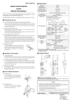
・ When ready, turn POWER switch ② ON. Select the sensor to be used with button ③ and the
number of cylinders of the engine to be measured with button ④ and then adjust the trigger level
using trigger level setup buttons ⑤ and ⑥ until the indicated value is stabilized. The rotating
signal can be monitored with indicator lamp IND ⑦ .
When the POWER switch is turned ON, all indicator lamps on the front panel may start
blinking.
This occurs when there are conflicts in the internal nonvolatile memory caused by turning
the power OFF while updating the nonvolatile memory or other reasons, but it is not a fault.
Press any button on the front panel to initialize the nonvolatile memory to the default states,
making it available. Please note that, in this case, the panel conditions saved previously will
be cleared, requiring resetting.
The panel conditions are automatically stored when no button operations are performed from
the front panel during a period of one second.
Power supply
Connector
Consumption current
Operating temperature range
Storage temperature range
Operating relative humidity range
Storage relative humidity range
Outside dimensions
Mass
Analog output cable
Pulse output cable
Power cable
Instruction manual
DC INPUT
12-24 V
1
IP-292 / 296
F
2
Signal COM
VP-202 / OM-200
1
2
2
3
4
5
3
4
LG-916
TTL
6
8
SENSOR
4
2CYCLE
10
12
A
E
Housing
ground
A
N.C
B
D
3
4CYCLE
8
5
10
6
6
12
14
PULSE
ANALOG
SIG
C
C
A
B
C
B
+12 V
Housing
+ − ground
White Green
+
−
Red Black
CYLINDER
1
LG-916
TTL
Power COM
(6)
IP-3000
One, 1.9m
One, 1.9m
One, 3.4m
One copy
5.Connector Pin Assignments
4 3
onosokki
12 to 24VDC
RM12BRB-2P (HIROSE ELECTRIC)
Approximately 500 mA (for 12VDC)
0 to +40°C
-10 to +60°C
Maximum 80%RH (With no condensation)
Maximum 80%RH (With no condensation)
221 (W) x 116 (H) x 150 (D)
1.3 kg
4.6 Accessories
・ When another detector other than TTL input one, has been selected, GAIN SELECT button ⑧
and the trigger level setup buttons are enabled. Signal detection may be difficult depending on
the engine ignition system and/or the type of sensor used; in such a case, the input sensitivity
can be raised up to 20 times. Note that, though raising the gain allows to measure small signals,
it also increases malfunctions due to noise.
・ When measuring a rotation number exceeding 10,000 r/min, select the 20,000 r/min range using
range selection button RANGE ⑨ .
Read the indicated value using the scale inside the meter.
q w
4.5 General Specifications
Housing
+ − ground
White Green
Connector names and manufacturers
7
RANGE
×1
×5
POWER
2
20000 r/min
× 10
× 20
GAIN SELECT
TRIGGER LEVEL
IND
1
4
16
2
0
18
0
8
9
20
×1000
r/min
10
SE-1620
1
(10)
0 e
221
2
(6)
Engine Tachometer
150
Power supply
LG/TTL IN
ANALOG
PULSE
Connector plug
RM12BPG-2S
R03-PB6M
R03-PB3M
R03-PB3M
Connector receptacle
RM12BRB-2P
R03-RB6F
R03-RB3F
R03-RB3F
Manufacturer
HIROSE
ELECTRIC
116
10000 r/min
TAJIMI
TAJIMI
ELECTRONICS ELECTRONICS
TAJIMI
ELECTRONICS
98 6 5 7
3. Connecting Output Connectors
When using ANALOG OUT ⑩ or PULSE OUT ⑪ , connect the related device using the associated cable.
Both outputs are of floating ground type and insulated from the unit housing.
3.1 ANALOG OUT
■ Omission of Issuance of Certificate
・The ANALOG OUT connector outputs analog signal of 0 to 10V in both the 10,000 r/min and
20,000 r/min ranges.
Connect the white cable to the plus side and the green cable to the minus side and give a load of
10k Ω or more. Take care not to short-circuit the outputs.
■ Warranty
1. This product is covered by a warranty for a period of one year from the date of purchase.
3.2 PULSE OUT
・ The PULSE OUT connector outputs square wave with pulse width 2ms and pulse height 4.5V
or more, obtained by converting two rotations of the input signal to one pulse.
Connect the white cable to the plus side and the green cable to the minus side.
Because this connector is not of open-collector type, do not apply external voltage to it.
2. This warranty covers free-of-charge repair during the warranty period for defects occurred while the
product is used under normal operating conditions according to descriptions in this manual and notices
on the unit label.
3. For free-of-charge repair during the warranty period, contact your dealer or your nearest Ono Sokki sales
office nearby.
4. Even during the warranty period, the following failures will be handled on a fee basis.
(a) Failures or damages occurring through misuse, misoperation, or modification
4. Specifications
(b) Failures or damages occurring through mishandling (dropping) during transportation after purchase
(c) Failures or damages occurring through natural calamities (fires, earthquakes, flooding, and lightening)
, environmental disruption, or abnormal voltage
4.1 Measurement Ranges
2-cycle engines
This product has been tested under strict inspections for normal operation before shipment. Please note
that the issuance of certificate is omitted.
1 or 2 cylinders
3 cylinders
4 cylinders
: 500 to 20,000 r/min
: 500 to 16,000 r/min
: 500 to 12,000 r/min
(d) Replenishment of expendable supplies, spare parts, and accessories.
*Outer appearance and specifications are subject to change without prior notice.
4-cycle engines
1 to 5 cylinders
6 cylinders
8 cylinders
10 cylinders
12 cylinders
: 500 to 20,000 r/min
: 500 to 16,000 r/min
: 500 to 12,000 r/min
: 500 to 10,000 r/min
: 500 to 8,000 r/min
onosokki
HOME PAGE: http://www.onosokki.co.jp/English/english.htm
WORLDWIDE
Ono Sokki Co., Ltd.
1-16-1 Hakusan, Midori-ku,
Yokohama 226-8507, Japan
Phone : 045-935-3976
Fax : 045-930-1906
E-mail : [email protected]