1
Thank you for selecting OMRON product. This sheet primarily describes precautions required in installing and
operating the product.
Before operating the product, read the sheet thoroughly to
acquire sufficient knowledge of the product. For your convenience, keep the sheet at your disposal.
TRACEABILITY INFORMATION:
Importer in EU:
Omron Europe B.V.
Wegalaan 67-69
2132 JD Hoofddorp,
The Netherlands
22
1
74
+10
0 0
2000
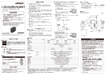
4-M3 depth 8
FOCUS
LIGHT
Extra Light Connector
・ Do not use thinner, benzene, acetone or kerosene to
clean the Sensor Head and Amplifier Unit.
・ To remove smaller dust particles, wipe gently with a
soft cloth. Do not use excessive force to wipe off dust
particles.
Manufacturer:
Omron Corporation,
Shiokoji Horikawa, Shimogyo-ku,
Kyoto 600-8530 JAPAN
74
74±0.1
INSTRUCTION SHEET
103
70
(Emitting Surface)
70
ZFV-LTF01
Smart Sensor
For Model ZFV-SC50□/90□
EXTERNAL LIGHTING (BACK LIGHTING)
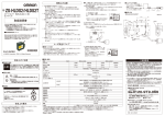
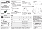
Dimensions
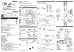
Insert the External Lighting connector into the Extra Light
connector of the Sensor Head.
109
Model
Please observe the following precautions to prevent
failure to operate, malfunctions, or undesirable effects on
product performance.
(1) Power Supply and Wiring
・ Before connecting/disconnecting the External
Lighting, make sure that the Smart Sensor is turned
OFF. The Smart Sensor may break down if the
External Lighting is connected or disconnected while
the power is ON.
・ Use only combinations of External Lightings and
Sensor Heads specified in this sheet.
(2) Maintenance and Inspection
Connecting the Sensor Head
(Emitting Surface)
PRECAUTIONS FOR CORRECT USE
74±0.1
Mounting hole dimensions
( Unit : mm )
The following notice applies only to products that carry the CE mark:
Notice:
This is a class A product. In residential areas it may cause radio
interference, in which case the user may be required to take adequate
measures to reduce interference.
© OMRON Corporation 2006-2015 All Rights Reserved.
PRECAUTIONS FOR SAFE USE
Please observe the following precautions for safe use of
the products.
(1) Installation Environment
・ Do not use the product in environments where it can
be exposed to inflammable / explosive gas.
・ To secure the safety of operation and maintenance, do
not install the product close to high-voltage devices
and power devices.
・ During installation, make sure that screws are
tightened firmly.
(2) Power Supply and Wiring
・ High-voltage lines and power lines must be wired
separately from this product. Wiring them together or
placing them in the same duct may cause induction,
resulting in malfunction or damage.
(3) Others
・ Moderate burn may possibly occur. Lightings is hot
immediately after power off. Do not touch it.
・ Do not attempt to dismantle, repair, or modify the
product.
・ Dispose of this product as industrial waste.
Specifications
Item
ZFV-LTF01
Applicable sensor head ZFV-SC50/SC50W/SC90/SC90W
Lighting method
Pulse lighting
Lighting pulse width
Fixed width (1.1~1.4ms)
Light Source
Sixty white LEDs
Power supply voltage
48 VDC (Supplied from Sensor Head.)
Current consumption
Approx. 160 mA
Dielectric strength
1000 VAC, 50/60 Hz for 1 min
Vibration resistance
10 to 150 Hz, 0.35-mm single amplitude,
(destruction)
10 times each in X, Y, and Z directions for 8 min
Shock resistance
150 m/s2 , three times each in six directions
(destruction)
(up/down, left/right, forward/backward)
Ambient temperature
Operating: 0 to 40 ℃, Storage: -20 to 65 ℃
(with no icing or condensation)
Ambient humidity
Operating and storage: 35% to 85%
(with no condensation)
Ambient atmosphere
Must be free of corrosive gas.
Connection method
Prewired, Standard cable length: 2 m
Degree of protection
IEC60529, IP20
Materials
SPCC
Weight
Approx. 500 g (550 g)
Suitability for Use
Omron Companies shall not be responsible for conformity with any standards,
codes or regulations which apply to the combination of the Product in the
Buyer’s application or use of the Product. At Buyer’s request, Omron will
provide applicable third party certification documents identifying ratings and
limitations of use which apply to the Product. This information by itself is not
sufficient for a complete determination of the suitability of the Product in
combination with the end product, machine, system, or other application or
use. Buyer shall be solely responsible for determining appropriateness of the
particular Product with respect to Buyer’s application, product or system.
Buyer shall take application responsibility in all cases.
NEVER USE THE PRODUCT FOR AN APPLICATION INVOLVING
SERIOUS RISK TO LIFE OR PROPERTY WITHOUT ENSURING THAT THE
SYSTEM AS A WHOLE HAS BEEN DESIGNED TO ADDRESS THE RISKS,
AND THAT THE OMRON PRODUCT(S) IS PROPERLY RATED AND
INSTALLED FOR THE INTENDED USE WITHIN THE OVERALL
EQUIPMENT OR SYSTEM.
See also Product catalog for Warranty and Limitation of Liability.
OMRON Corporation
Tokyo, JAPAN
Industrial Automation Company
Contact: www.ia.omron.com
Regional Headquarters
OMRON EUROPE B.V.
Sensor Business Unit
Carl-Benz-Str. 4, D-71154 Nufringen, Germany
Tel: (49) 7032-811-0/Fax: (49) 7032-811-199
OMRON ELECTRONICS LLC
2895 Greenspoint Parkway, Suite 200
Hoffman Estates, IL 60169 U.S.A.
Tel: (1) 847-843-7900/Fax: (1) 847-843-7787
OMRON ASIA PACIFIC PTE. LTD.
No. 438A Alexandra Road # 05-05/08 (Lobby 2),
Alexandra Technopark,
Singapore 119967
Tel: (65) 6835-3011/Fax: (65) 6835-2711
OMRON (CHINA) CO., LTD.
Room 2211, Bank of China Tower,
200 Yin Cheng Zhong Road,
PuDong New Area, Shanghai, 200120, China
Tel: (86) 21-5037-2222/Fax: (86) 21-5037-2200
D s Oct, 2014