1
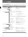
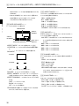
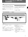
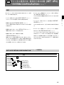
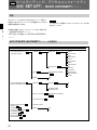
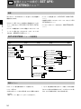
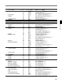
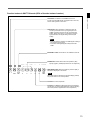
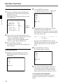
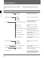
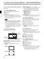
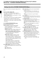
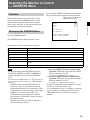
[C1] Setting the Input Configuration (SET UP 1)
— INPUT CONFIGURATION Menu
Overview
Chapter 2 Menu
Data pertaining to the input signals are set with the
INPUT CONFIGURATION menu.
When a channel number (1 to 90) is entered with the
numeric keypad, it is then possible to set which input
connector on the rear panel will be assigned to that
channel number, and select the type of signal that will
be connected.
The following data can be set with the INPUT
CONFIGURATION menu.
• Assigning the signal FORMAT
• Selecting the SCAN CONVERSION
• Selecting the LINK NO
• Selecting the SYNC MODE
• Selecting the SCREEN MODE
• Selecting the SAFE AREA DISPLAY
• Setting the SAFE AREA MODE
• Assigning CHANNEL NAME
• Selecting the picture CONTROL settings
• Setting the COLOR TEMP (temperature)
• Adjusting H PHASE
• COPYing FROM other data
Note
Data copy is impossible between monitors other than
BVM-F24 series.
28
Channels 91 to 99 assignment
The channel numbers from 91 to 99 are assigned to
internal signals.
091: PLUGE signal (Picture Line Up Generating
Equipment)
092: 20% gray signal
093: 100% white signal
094: five-step gray scale signal
095: cross hatch signal
096: cross hatch signal
097: dot signal
098: cross hatch signal
099: 0% black signal