1
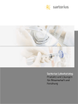
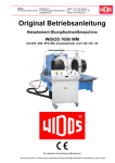
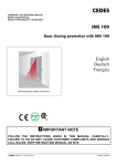
°C
Manual
Incubator XL-3
CO2
°C
Heating Unit
CO2-Controller
Tempcontrol 37-2 digital
CO2-Cover
tempcont rol 37-2 digital
37.0
°C
37.0
+
+
on
1
E
2
power
+
+
of f
CTI-Controll er 3700
heater
nom
5.0 2
real
co ntr ol
CO 2 %
setpoint
2
normal
overheat
ventilation heating
speed
intensity
dis play
CO 2
reducing valve
valve
on
remote
power
off
Stabilization of the “in vitro environment”
for cell and tissue culture
37 °C
Laminar
air flow
5 .0 %
CO 2
7.0 %
O2
German – English
www.pecon.biz
Diese Bedienungsanleitung gehört zu diesem Produkt. Sie enthält wichtige Hinweise zur Inbetriebnahme und zur Handhabung. Machen Sie sich daher bitte mit dem Inhalt vertraut und beachten Sie
besonders die Hinweise, die der sicheren Bedienung des Gerätes dienen. Achten Sie hierauf, auch
wenn Sie dieses Produkt an Dritte weitergeben. Heben Sie deshalb diese Bedienungsanleitung zum
Nachlesen auf!
Änderungen, die dem technischen Fortschritt dienen, bleiben vorbehalten. Das Manual unterliegt
keinem "Update-Service".
Solange keine ausdrückliche Genehmigung vorliegt, ist die Weitergabe und Vervielfältigung dieses
Dokuments und die Benutzung und Verbreitung seiner Inhalte nicht gestattet. Verstöße verpflichten zur
Zahlung von Entschädigung.
Alle Rechte vorbehalten, die im Falle der Gewährung von Patenten und Gebrauchsmustern entstehen.
Alle in diesem Handbuch erwähnten Produktnamen können Warenzeichen oder eingetragene
Warenzeichen der jeweiligen Eigentümer sein und sind nicht überall ausdrücklich durch "TM" und "®"
gekennzeichnet.
© 2005
These operating instructions form an integral part of this product. It contains important information on
installing and using the product. Please keep this in mind, especially when passing this product on to
third parties. For this reason, keep the operationg instructions for future reference!
Design and specifications are subject to change without notice. The manual is not covered by an
update service.
Unless expressly authorized, forwarding and duplication of this document, and the utilization and
communication of its contents are not permitted. Violations will entail an obligation to pay
compensation.
All rights reserved in the event of granting of patents or registration of a utility model.
All product names mentioned herein may be the trademarks or registered trademarks of their
respective companies and "TM" and "®" are not mentioned in each case in this manual.
© 2005
Inkubator XL-3
PeCon # 0431.400
Passend für:
Zeiss # 000000-1272-122
Zeiss Axiovert 200 + 200M
kompatibel mit ApoTome
Inhaltsverzeichnis
Kurzbeschreibung .................................................................................................................................... 1
Lieferumfang ........................................................................................................................................... 2
Bestimmungsgemäßer Einsatz ................................................................................................................ 2
Sicherheits- und Gefahrenhinweise ......................................................................................................... 2
Bedienelemente...................................................................................................................................... 3
Montage.................................................................................................................................................. 4
Inbetriebnahme....................................................................................................................................... 7
Hinweise................................................................................................................................................... 8
Wartung und Reinigung........................................................................................................................... 8
Fehlersuche ............................................................................................................................................. 9
Technische Daten.................................................................................................................................. 10
Kurzbeschreibung
•
Leichte und schnelle Montage. Kein Werkzeug erforderlich.
•
Große Scharniertüren links und rechts in der Vorderfront, darunter befinden sich Öffnungen mit 3 Schiebetüren.
•
Durchgang für Kabel und Schläuche links und rechts in der Rückwand
(Schiebetüren mit Arretierung). Bodeneinschübe, links und rechts, mit
Aussparungen für Objektführer (Koaxialtrieb) und Silikonabdichtung.
Rechts befindet sich eine Öffnung für einen Lichtleiter (Poly V Faser).
•
Kompatibel zu allen Kondensoren. Mikromanipulatoren verschiedener
Hersteller einsetzbar (z.B. Eppendorf, Narishige). Das ApoTome kann
auch bei montiertem Inkubator aus- und eingebaut werden.
•
Homogene Warmluftverteilung durch zentrale Luftzufuhr von hinten.
•
Zum Betrieb wird eine weitere heizbare Komponente (z.B. Heizeinsatz P,
Heizbarer Mikroskoptisch) empfohlen. Für Spezialanwendungen (z.B.
Multischalen mit Glasboden) kann der Inkubator XL-3 nur mit der
Heating Unit betrieben werden.
•
Eine lokale CO2-Inkubation kann durch Verwendung des CO2-Controllers in Kombination mit passenden CO2-Deckeln durchgeführt werden.
Vorderansicht
Rückansicht
24.11.2005
www.pecon.biz
2
Manual: Inkubator XL-3
Lieferumfang
Anzahl
Artikel-Nr.
Temperatursensor-Verbindungskabel
1
# 0427.001
Temperatursensor mit Kabel + Klett-Befestigungspunkte
1
# 0431.101
Luftführungsschlauch-Set
Kabelhalter, selbstklebend (4 Stck.)
1
1
# 0431.207
# 0431.204
Bedienungsanleitung
1
Ersatzteile:
Klett-Befestigungspunkte (6 Stck.)
1
# 0431.104
Steckermodul für Temperatursensor
1
# 0431.106
Rändelschraube, schwarz, M8x20
1
# 0431.414
Einschubboden, links
1
# 0431.102
Einschubboden, rechts - ApoTome
1
# 0431.403
Lampenträgerabdichtung, links
Lampenträgerabdichtung, rechts
1
1
# 0431.410
# 0431.411
Rändelschraube, schwarz, M6x10
2
# 0431.413
Schiebetüre mit 4 Durchgängen
1
# 0431.110
Knopf mit Schraube, blau
1
# 0431.111
Bestimmungsgemäßer Einsatz
•
Dieser Inkubator dient der Schaffung eines gleichmäßig erwärmten Luftbereiches um den Mikroskoptisch, der den Kondensor, den Objektivkranz und auch Mikromanipulatoren einschließt.
•
Zur Versorgung des Inkubators mit Warmluft ist die Heating Unit in Kombination mit dem Tempcontrol 37-2 digital zu verwenden.
•
Das Material des Inkubators ist für die üblichen Inkubationstemperaturen von Zell- und Gewebekulturen ausgelegt (typisch 37°C; max. 50°C).
•
Eine Erhöhung der Luftfeuchte, sowie der CO2-Konzentration im gesamten Inkubatorinnenraum ist
nicht zulässig. Zur Kontrolle dieser Parameter innerhalb dieses Inkubators stehen lokale Lösungen
zur Verfügung.
Eine andere Verwendung als zuvor beschrieben kann zur Beschädigung dieses Produktes und weiteren, damit verwendeten Komponenten, führen. Außerdem ist dies mit Gefahren wie z.B. Kurzschluss,
Brand, elektrischer Schlag etc. verbunden. Das gesamte Produkt darf nicht geändert bzw. umgebaut
werden! Die Sicherheitshinweise sind unbedingt zu beachten!
Bei nicht bestimmungsgemäßem Betrieb gehen sämtliche Garantieansprüche verloren. Der Hersteller
haftet nicht für Schäden, die sich aus dem nicht bestimmungsgemäßen Betrieb des Geräts ergeben.
Weiterhin haftet der Hersteller nicht für Folgeschäden, es sei denn, es wird Vorsatz oder grobe Fahrlässigkeit nachgewiesen.
Sicherheits- und Gefahrenhinweise
= Hinweise, die der Sicherheit des Benutzers, sowie zur Vermeidung der Beschädigung des
Gerätes dienen. Lesen Sie die Gebrauchsanweisung!
= Hinweise, die für einen problemlosen Betrieb unbedingt beachtet werden müssen!
www.pecon.biz
24.11.2005
3
Manual: Inkubator XL-3
•
Der scharfkantige Federstahl des flexiblen Warmluftschlauches kann unter Umständen an den
Schlauchenden hervortreten.
•
Bei Verwendung des Inkubators zusammen mit einer lokalen CO2-Begasung ist auf eine
ausreichende Belüftung des Raumes zu achten, um die Akkumulation einer schädlichen CO2Konzentration (ab ca. 0,5 Vol-%) zu verhindern.
•
Wenn anzunehmen ist, dass ein gefahrloser Betrieb nicht mehr möglich ist, so ist das Gerät außer
Betrieb zu setzen und gegen unbeabsichtigten Betrieb zu sichern. Es ist anzunehmen, dass ein
gefahrloser Betrieb nicht mehr möglich ist, wenn:
-
das Gerät sichtbare Beschädigungen aufweist;
-
Nach längerer Lagerung unter ungünstigen Verhältnissen oder
nach schweren Transportbeanspruchungen.
-
•
Beachten Sie auch die Sicherheitshinweise in den einzelnen Kapiteln bzw. in den Bedienungsanleitungen der angeschlossenen Geräte.
Bedienelemente
1 2
3
4
5 6
14
7
9
10
13
12
11
(1) Griff zum Öffnen der linken Lampenträgerabdichtung
(2) Feststellknopf für linke Lampenträgerabdichtung
(3) Linke Lampenträgerabdichtung
(4) Rechte Lampenträgerabdichtung
(5) Feststellknopf für rechte Lampenträgerabdichtung
(6) Griff zum Öffnen der rechten Lampenträgerabdichtung
(7) Rechte obere Scharniertüre – Zugang zum Mikroskoptisch und Kondensor
(8) Arretierung für Einschubboden, rechts
(9) Durchgang für Lichtleiterfaser
(10) Einschubboden, rechts - ApoTome
(11) Rechte untere Schiebetüren – Zugang zu Objektiven, Filtern und ApoTome
(12) Linke untere Schiebetüre – Zugang zu Objektiven und Filtern
(13) Einschubboden, links
(14) Linke obere Scharniertüre – Zugang zum Mikroskoptisch und Kondensor
24.11.2005
www.pecon.biz
4
Manual: Inkubator XL-3
15
16
17
18
(15) Rechte hintere Schiebetüre – Durchgang für Kabel und Schläuche
(16) Anschluss für Luftführungsschlauch (Warmluft)
(17) Steckermodul für Temperatursensor
(18) Linke hintere Schiebetüre – Durchgang für Kabel und Schläuche
Montage
Anschlussschema
Luftstrom
Verbindungskabel (für Sensor)
Verbindungskabel (für Geräte)
Heating
Unit
Tempcontrol
37-2 digital
tempcontrol 37-2 digital
37.0
°C
37.0
+
+
on
power
Sensorkabel
+
off
1
E
2
+
Axiovert 200
Beobachtungsbereich
TemperaturHeizbarer Mikroskoptisch
sensor
Kabel
Heizbarer
Mikroskoptisch
Scanningtisch
Mechanischer Kreuztisch
www.pecon.biz
24.11.2005
5
Manual: Inkubator XL-3
Beschreibung
Lampenträgerabdichtung öffnen
Befestigungsknopf
Befestigungsknopf
Warmluft
Zufuhr
Bodeneinschübe
(rechts und links)
Steckermodul
(Sensorkabel)
Schiebtüren Durchgang
für Kabel, Schläuche
•
Klebebänder (Transportsicherung) vom Inkubator entfernen und beide Bodeneinschübe (10) und
(13) seitlich herausziehen. Der linke Boden muss dazu innen zuerst leicht nach oben gekippt
werden, damit er aus den Arretierstiften rutscht, der rechte vorher entriegelt werden (8). Die rot
gekennzeichneten Transportsicherungsstopfen entfernen.
•
Heizbaren Mikroskoptisch mit Objektführer, mechanischen Kreuztisch oder Scanningtisch mit Heizeinsatz P oder Heizeinsätzen M06-96 montieren, ebenso Kondensor und Objektive befestigen,
gegebenenfalls Mikromanipulatoren anbringen.
•
Kabel und Schläuche der Komponenten rechts und links vom Mikroskop auf den Tisch legen.
Endabschalter (y-Achse) des Scanningtisches so einstellen, dass der bewegliche Teil nicht nach
vorn über die Tischbegrenzung hinausfährt (Auflagefläche für Inkubator XL-3).
•
Vor Aufsetzen des Inkubators auf das Mikroskop muss der Lampenträger eingeschwenkt und der
vordere Haltegriff (zwischen Tubus und Mikroskoptisch) mit einem Inbusschlüssel entfernt werden.
•
Die Lampenträgerabdichtungen (3) und (4) oben auf dem Inkubator vollständig öffnen: Dazu
Drehknöpfe (2) und (5) öffnen und beide Schieber an den Griffen (1) und (6) nach rechts bzw.
links schieben.
•
Inkubator XL-3 (ohne Bodeneinschübe) vorsichtig von oben über das Mikroskop führen und positionieren. Vorne muss der Inkubator XL-3 zwischen Okulartubus und Mikroskoptisch aufliegen
(Abb. 1), die hintere Auflage sitzt in richtiger Position auf dem trapezförmigen Teil des Mikroskopstativs (Abb. 2).
Abb. 1: Korrekte vordere Inkubatorposition.
24.11.2005
Abb. 2: Korrekte hintere Inkubatorposition.
www.pecon.biz
6
Manual: Inkubator XL-3
•
Die oberen Abdichtungsschieber am Lampenträger
schließen. Darauf achten, dass das Lampenkabel durch
die dafür vorgesehene Öffnung in der Silikonplatte läuft
(Abb. 3). Die richtige Platzierung des Kabels in der Silikonplatte unten am Lampenkabelausgang ebenfalls überprüfen.
•
Ein eventuell am Lampengehäuse (CZ# 447219-0000-000)
angebrachter Streulichtschutz muss entfernt werden, da
sich anderenfalls die Abdichtungsschieber nicht schließen
lassen.
•
Durch die hinteren Schiebetüren (15) und (18) werden die
Kabel bzw. Schläuche nach außen geführt. In der obersten
Position werden die Türen automatisch fixiert.
•
Temperatursensor von innen an das hintere Steckermodul (17) anschließen. Durch Drehen mit
leichtem Druck rutscht der Kabelstecker (5 pol.) leicht in die richtige Position und kann durch
Rechtsdrehung gesichert werden.
•
Den Sensor mit einem Klettpunkt befestigen (siehe unbedingt Abschnitt "Sensorposition", Seite 7).
Das Sensorkabel so führen, dass es nicht zwischen beweglichen Teilen (z.B. Scanningtisch) eingeklemmt werden kann. Kabel eventuell mit Kabelhaltern befestigen.
•
Rechten und linken Bodeneinschub einsetzen. Der linke Bodeneinschub (13) rastet in Endposition
in kurze Stifte ein. Der rechte Einschub (10) wird durch einen blauen Verschluss (8) arretiert. Bei der
Montage muss beachtet werden, dass die Führungsstangen vom Objektführer bzw. mechanischem Kreuztisch genau in die Bahnen (mit Silikonplatte abgedichtet) der Bodeneinschübe geführt werden.
•
Heating Unit rechts oder links hinter den Inkubator stellen
und mit dem Luftführungsschlauch an den Inkubator XL-3
anschließen. Dazu den Schlauch zuerst mit dem Plexiglasadapter auf die hintere Luftzufuhr (16) stecken und mit der
schwarzen M8 Kunststoffschraube sichern. Danach den
Schlauch mit dem Adapter auf den oberen Luftausgang
der Heating Unit stecken.
•
Zur Entkopplung von eventuell störenden Schwingungen
(Ventilator) kann die Heating Unit auf einen separaten Tisch
oder auf ein Regal gestellt werden.
Abb. 3: Führung des Lampenkabels
der HAL 100 durch die Silikonplatte.
Abb. 4: Anschluss des Inkubators an
die Heating Unit über den
Luftführungsschlauch.
Kabelverbindungen
1. Heating Unit und Tempcontrol 37-2 digital mit dem Geräteverbindungskabel verbinden.
2. Verbindungskabel (für Sensor) zwischen Heating Unit und Steckermodul (17) montieren, wobei die
Kabelbuchse (5-polig) durch Drehen mit leichtem Druck in die richtige Position des Einbausteckers rutscht – Verbindung arretieren. Schraubverbindung bitte nur leicht anziehen !
3. Temperatursensor: Der Stecker des Kabels wird im Inkubator in die Einbaubuchse am Steckermodul (17) geschoben, Stecker hierbei ebenfalls durch Drehung und leichtem Druck in Position
bringen – Verbindung arretieren. Schraubverbindung ebenfalls nur leicht anziehen !
www.pecon.biz
24.11.2005
7
Manual: Inkubator XL-3
Inbetriebnahme
Empfohlene Einstellungen für die Heating Unit
Aufheizphase:
Arbeitsphase:
heating intensity:
ventilation speed:
heating intensity:
ventilation speed:
3
7
2 bzw. 3
1-4 bzw. 4-7
•
Für weitere Informationen zu den Einstellungen siehe auch Anleitung Heating Unit.
•
Den richtigen Regelparametersatz am verwendeten Kanal des Tempcontrol 37-2 digital auswählen (siehe Manual Tempcontrol 37-2 digital).
Bis zum Erreichen einer Arbeitstemperatur von 37°C dauert es in Abhängigkeit von der
Raumtemperatur ca. 2-3 h. Diese Zeit ist nötig, um das Mikroskop und alle weiteren Komponenten auf die gewünschte Temperatur zu erwärmen. Dies gilt vor allem, wenn keine
weiteren beheizten Komponenten verwendet werden.
•
Falls der Sollwert nicht erreicht wird, muss die Heizleistung "heating intensity" und/oder die Luftgeschwindigkeit "ventilation speed" erhöht werden. Unter Umständen ist auch eine Erhöhung der
Raumtemperatur (optimal ca. 22°C) notwendig.
•
Der Lampenträger kann bei aufgesetztem Inkubator nach hinten geklappt werden. Dazu vorher
beide Abdichtungsschieber (3) und (4) öffnen. Das Öffnen der Abdichtungsschieber im Betrieb
bedeutet jedoch kurzfristig einen zeitweisen Wärmeverlust. Beim Wiederverschließen auf den richtigen Sitz des Lampenkabels in der Silikonplatte achten.
Empfehlungen für die Sensorpositionen
Die Position des Sensors ist ausschlaggebend für eine adäquate Temperatur im Beobachtungsbereich. Die Temperatur ist u.a. abhängig von der Masse der Komponenten im Inkubator und ihrer Verteilung, vom oft unterschiedlichen Wärmeabfluss und der Außentemperatur. Zusätzlich ist es wichtig,
dass beim Arbeiten mit kultivierten Zellen im "offenen" System (z.B. Petrischale) die Luftbewegung im
Inkubator nicht zu stark ist, da sonst pro Zeiteinheit mehr Wassermoleküle aus den Nährmedien etc. in
die Atmosphäre entweichen. Durch den Wasserverlust nimmt die Ionenstärke im wässrigen Medium
zu und kann zu einem Absterben der Zellen führen.
Der Sensor wird durch Klettband festgehalten, wobei der Nutzer durch Aufkleben einer Klettplatte
(Zubehör) die Position bestimmen bzw. ändern kann.
Bei einer schlechten Position des Sensors kann es zu stärkeren Temperaturschwankungen
kommen oder die Temperatur am Ort des Sensors erreicht nicht die eingestellte Solltemperatur. Zusätzlich ist es möglich, dass die Temperatur im Beobachtungsbereich nicht dem
gewünschten Wert entspricht.
•
Scanningtisch, mechanischer Kreuztisch und Objektführer:
Es wird empfohlen den Temperatursensor hinter dem Tisch
mittig vor dem Lampenträger anzubringen (Abb. 5).
Bei Verwendung von Mikromanipulatoren der Firma Eppendorf muss der Sensor auf der Adapterplatte für Mikromanipulation an der hier angegebenen Position angebracht
werden.
Je nach verwendeten Mikroskopkomponenten kann eine
andere Position des Temperatursensors nötig sein, z.B.
mittig vor dem Kultivierungsgefäß.
Abb. 5: Anbringung des Temperatursensors.
24.11.2005
www.pecon.biz
8
Manual: Inkubator XL-3
Hinweise
•
Zur Bedienung des ApoTome kann die rechte untere Schiebetüre nach beiden Seiten hin
geöffnet werden. Das ApoTome lässt sich bei aufgesetztem Inkubator XL-3 entnehmen, indem der rechte Bodeneinschub (10)
nach Entriegelung (siehe Abb.) seitlich herausgezogen wird. Zur
Minimierung vom Wärmeverlusten im Betrieb sollte der Bodeneinschub so rasch wie möglich wieder eingesetzt werden.
•
Bei Verwendung des Inkubator XL-3 zusammen mit dem mechanischen Kreuztisch und den Heizeinsätzen M06 bis M96 können die Vertiefungen in der hinteren Reihe der Multischale (nahe des
Lampenträgers) nicht beobachtet werden.
•
Den Universalhalterahmen KX so in den mechanischen Kreuztisch einsetzen, dass die Befestigungsschieber des Rahmens hinten zu liegen kommen. Dadurch können alle Vertiefungen der
eingesetzten Multischale beobachtet werden.
•
Zur Arbeit mit Multischalen mit Glasboden ist der spezielle Universalhalterahmen KM erhältlich. Die
Beheizung der Multischale erfolgt dabei durch die Warmluft im Inkubator. Zusätzlich ist eine lokale
CO2-Inkubation mit dem CO2-Deckel HM und dem CO2-Controller möglich.
Wartung und Reinigung
•
Der Inkubator ist bis auf eine gelegentliche Reinigung wartungsfrei.
•
Wenn nötig kann der Inkubator von außen mit einem fusselfreien, sauberen, antistatischen und
leicht angefeuchteten Tuch abgewischt werden.
•
Keine scheuernde, chemische und lösemittelhaltige Reinigungsmittel verwenden! Am besten
eignet sich Plexiglasreiniger oder Wasser mit milden Detergenzien (Spülmittel).
Zur Reinigung keine Reinigungsmittel mit Alkohol verwenden, da Spannungsrisse entstehen
können.
Der Inkubator ist nicht autoklavierbar.
www.pecon.biz
24.11.2005
9
Manual: Inkubator XL-3
Fehlersuche
Mit diesem Inkubator haben Sie ein Produkt erworben, welches zuverlässig und betriebssicher ist.
Dennoch kann es zu Problemen oder Störungen kommen.
Im Folgenden möchten wir Ihnen beschreiben, wie Sie mögliche Störungen leicht selbst beheben
können.
Beachten Sie unbedingt die Sicherheitshinweise.
Problem:
Ursache / Lösung:
1. Die Luft im Inkubator erreicht nicht die eingestellte Temperatur am Tempcontrol
37-2 digital.
a) Die Heizleistung der Heating Unit passt nicht zu
den Umgebungs- und Systembedingungen.
Daher muss die Heizleistung „heating intensity“
und/oder die Luftgeschwindigkeit „ventilation
speed“ erhöht werden.
b) Sind bereits die maximalen Einstellungen an der
Heating Unit ausgewählt, so muss die Umgebungstemperatur (optimal 22°C) erhöht werden.
Auch der Luftstrom von Klimaanlagen kann negative Auswirkungen auf die Inkubatortemperatur
haben.
c) Der Temperatursensor befindet sich an einer ungünstigen Position, z.B. in der Nähe der kälteren
Inkubatoraußenwände. Den Sensor neu positionieren (siehe Seite 7).
d) Es dauert je nach Umgebungstemperatur ca. 2
bis 3 h ehe der Inkubator die eingestellte Temperatur erreicht.
2. Die am Tempcontrol 37-2 digital angezeigte Temperatur der zusätzlichen heizbaren Komponente (z.B. Heizeinsatz P
oder Heiztisch) steigt über den Sollwert an.
Dieses Problem tritt auf, wenn die Einstellungen der
Heating Unit („heating intensity“ / „ventilation speed“)
zu hoch gewählt sind. Dann erwärmt die einströmende Luft die zusätzliche Komponente so stark,
dass sich diese über den Sollwert erwärmt.
Es empfiehlt sich die Einstellungen der Heating Unit
zu verringern. Eventuell muss auch der Sensor neu
positioniert werden, so dass er mehr im Luftstrom zu
liegen kommt. Dadurch wird die Heizleistung rascher
vom Tempcontrol 37-2 digital heruntergeregelt.
3. Die Temperatur im Beobachtungsbereich
entspricht nicht der gewünschten Solltemperatur, obwohl am Tempcontrol 37-2
digital die Inkubatortemperatur richtig angezeigt wird.
(Beim Einsatz des Inkubators ohne
zusätzliche heizbare Komponente)
24.11.2005
Die Temperatur im Beobachtungsbereich hängt
sowohl von der Sensorposition, als auch von den
verwendeten Komponenten im Inkubator ab (siehe
Seite 7).
Zur Lösung des Problems sollten verschiedene Sensorpositionen getestet werden. Befindet sich der
Sensor nahe der Warmluftzufuhr (bzw. im Luftstrom
der Heating Unit), so kann die Temperatur im Beobachtungsbereich zu niedrig sein, während sie zu
hoch sein kann, wenn der Sensor zu weit abseits
positioniert wird.
www.pecon.biz
10
Manual: Inkubator XL-3
4. Die Anzeige der Inkubatortemperatur
schwankt um den eingestellten Sollwert
um mehr als 0,1°C.
a) Der Sensor registriert eine veränderte
Warmluftzufuhr verzögert, so dass sich kein
stabiler Regelzustand einstellen kann.
Es sollten andere Sensorpositionen getestet
werden, in denen der Sensor etwas mehr im
Warmluftstrom der Heating Unit zu liegen kommt.
b) Die Einstellung des Regelparametersatzes am
Tempcontrol 37-2 digital ist nicht passend für die
Heating Unit (siehe Manual Tempcontrol 37-2
digital).
5. Die Zellen sterben frühzeitig ab bzw.
zeigen anormales Verhalten.
a) Für eine länger andauernde Inkubation ist eine
CO2-Begasung unbedingt notwendig. Dazu sind
der CO2-Controller und spezielle CO2-Deckel für
verschiedene heizbare Komponenten erhältlich.
b) Bei einer starken Luftbewegung im Inkubator
kann es zu einer deutlichen Verdunstung von
Wasser aus dem Medium kommen. Der daraus
resultierende Anstieg der Ionenkonzentration
kann für die Zellen letal sein. Zur Verringerung der
Evaporation sind spezielle Foliendeckel für verschiedene Zellkultivierungssysteme erhältlich.
c) Aufgrund einer ungünstigen Position des Temperatursensors ist die Temperatur im Beobachtungsbereich nicht ideal.
Zur Lösung siehe Problem 3.
Bei weiteren Fragen wenden Sie sich an unsere Technische Beratung:
e-mail:
web:
[email protected]
http://www.pecon.biz/pecon/support
Tel.
++49-7305-95666-0
Fax.
++49-7305-95666-90
Überprüfen Sie regelmäßig die technische Sicherheit des Gerätes z.B. auf Beschädigungen des Gehäuses usw.
Eine anderweitige Reparatur darf nur durch eine technische Fachkraft erfolgen, die mit
den damit verbundenen Gefahren bzw. einschlägigen Vorschriften vertraut ist. Bei eigenmächtigen Änderungen oder Reparaturen am oder im Gerät erlischt der Garantieanspruch.
Technische Daten
Material
Acrylglas
Temperaturbereich
10°C – 50°C
Gehäuse-Innenmaße (BxHxT)
Öffnung obere Scharniertüren (LxB)
600 x 370 x 380 (mm)
160 x 160 (mm)
Öffnung untere Schiebetüren (LxB)
110 x 90 (mm)
Gewicht
ca. 8,5 Kg
www.pecon.biz
24.11.2005
Incubator XL-3
PeCon # 0431.400
Suitable for:
Zeiss # 000000-1272-122
Zeiss Axiovert 200 + 200M
compatible with ApoTome
Contents
Description............................................................................................................................................. 11
Scope of delivery................................................................................................................................... 12
Usage in accordance with intended purpose...................................................................................... 12
Safety instructions and hazard warnings ............................................................................................... 12
Operating controls................................................................................................................................. 13
Assembly................................................................................................................................................ 14
Operation .............................................................................................................................................. 17
Tips ......................................................................................................................................................... 18
Maintenance......................................................................................................................................... 18
Troubleshooting ..................................................................................................................................... 19
Specifications ........................................................................................................................................ 20
Description
•
Easy and quick assembly. No tools necessary.
•
Large hinged openings in the front panel on the left and right hand
side, beneath are openings with 3 sliding doors.
•
Openings for cables and tubes in the back panel (sliding plates with
locks) on the left and right hand side. Slide-in base plates on the left
and right hand side with openings for object guide (silicone seal). At
the right side is a circular opening for the light guide (Poly V fibre).
•
Compatible to all condensers. Micromanipulators of various manufacturers can be used (e.g. Eppendorf, Narishige). The ApoTome can
be installed and removed while the incubator is mounted.
•
Homogenous warm air distribution by concentric air supply from the
back.
•
For the operation another heated component (e.g. Heating Insert P,
Heating Stage) is recommend. For special applications (e.g. multiwell
plates with glass bottoms) the Incubator XL-3 can be operated with the
Heating Unit alone.
•
A local CO2-incubation can be carried out with the CO2-Controller in
combination with appropriate CO2-Covers.
front view
rear view
24.11.2005
www.pecon.biz
12
Manual: Incubator XL-3
Scope of delivery
Qty.
Article-Nr.
Temperature sensor connecting cable
1
# 0427.001
Temperature sensor with cable + Velcro plates
1
# 0431.101
Air duct tube set
Adhesive Cable-Clip, 4 pcs
1
1
# 0431.207
# 0431.204
Manual
1
Spare parts:
Velcro pads (6 pcs)
1
# 0431.104
Plug module for temperature sensor
1
# 0431.106
Knurled screw, black, M8x20
1
# 0431.414
Slide-in base plate, left
1
# 0431.102
Slide-in base plate, right – ApoTome
1
# 0431.403
Lamp support sealing, left
Lamp support sealing, right
1
1
# 0431.110
# 0431.111
Knurled screw, black, M6x10
2
# 0431.413
Sliding door with 4 openings
1
# 0431.110
Knob with screw, blue
1
# 0431.111
Usage in accordance with intended purpose
•
This incubator is designed to get a homogeneously warmed area around the microscope stage,
which comprises the condenser, the objective nosepiece and also micromanipulators.
•
To supply the incubator with warm air the Heating Unit in combination with the Tempcontrol 37-2
digital must be used.
•
The material of this incubator is designed for the usual incubation temperatures of cell- and tissue
cultures (typically 37°C; max. 50°C).
•
An increase of humidity and the CO2-concentration inside the whole incubator is not allowed.
Special local solutions to control these parameters are available.
Use other than the described above will damage the product and other components, used with it. It
may additionally involve other risks, such as short circuit, fire and electric shock etc. Do not change or
modify any part of the product. The safety instructions must be observed without fail.
Any deviations from the application described here will forfeit all claims against warranty and the
manufacturer's liability in general and particularly in the event of a defect. Furthermore the
manufacturer is not liable for consequential damage, unless intention or gross negligence can be
proved.
Safety instructions and hazard warnings
= Notes for user safety and to avoid damage to the device. Read the instructions for use!
= Notes for a trouble-free operation of the device!
www.pecon.biz
24.11.2005
13
Manual: Incubator XL-3
•
The sharp-edged spring steel of the flexible air duct tube might possibly stick out of the tube
endings.
•
If the incubator is used with local CO2-gassing solutions a sufficient room ventilation must be
ensured, to prevent the accumulation of a harmful CO2-concentration (starting from approx. 0.5
vol-%).
•
If you have reasons to assume that safe operation is no longer possible, immediately take the
device out of operation and secure it against unintentional operation. Reasons to assume that
safe operation is no longer possible include:
-
the device shows signs of visible damage,
-
the device has been stored for long periods under unfavourable conditions or
has been subjected to considerable stress in transit.
-
•
You should also heed the additional safety instructions in each chapter of this manual as well as
in the manuals of the connected devices.
Operating controls
1 2
3
4
5 6
14
7
9
10
13
12
11
(1) Handle to open the left lamp support sealing
(2) Fixing knob for the left lamp support sealing
(3) Left lamp support sealing
(4) Right lamp support sealing
(5) Fixing knob for the right lamp support sealing
(6) Handle to open the right lamp support sealing
(7) Top right hinged door – Access to stage and condenser
(8) Lock for Slide-in base plate, right
(9) Opening for light guide fibre
(10) Slide-in base plate, right – ApoTome
(11) Bottom right sliding doors – Access to objectives and filters
(12) Bottom left sliding doors – Access to objectives and filters
(13) Slide-in base plate, left
(14) Top left hinged door – Access to stage and condenser
24.11.2005
www.pecon.biz
14
Manual: Incubator XL-3
15
16
17
18
(15) Rear right sliding door – opening for cable und tubing
(16) Connection for the air duct tube (warm air)
(17) Plug module for temperature sensor
(18) Rear left sliding door – opening for cable und tubing
Assembly
Connection diagram
air stream
connecting cable (for sensor)
connecting cable (for units)
Heating
Unit
Tempcontrol
37-2 digital
tempcontrol 37-2 digital
37.0
°C
37.0
+
+
on
power
sensor cable
+
temperature
sensor
www.pecon.biz
off
1
E
2
+
Axiovert 200
observation area
Heating
Stage
cable
Heating Stage
Scanning Stage
Mechanical Stage
24.11.2005
15
Manual: Incubator XL-3
Description
Open lamp support sealings
fixing knob
fixing knob
warm air
input
slide-in base plates
(right and left)
plug module
(sensor cable)
sliding plates openings
for cables, tubes
•
Remove the tape (transportation lock) from the incubator and pull out both slide-in base plates
(10) and (13). The left base plate must be tilted first on the inner side, so that it slips out of the
lateral locking pins. The right one must be unlocked first (8). Remove the red marked transportation locks.
•
Mount the Heating Stage with Object Guide, the Mechanical Stage or the Scanning Stage with
the Heating Insert P or Heating Inserts M06-96, also attach condenser and objectives, if necessary
attach micromanipulators.
•
Put cables and tubings of the components on the table to the right and left of the microscope.
Set the limit switch (y-axis) of the Scanning Stage so that the moveable part of the stage does not
go over the front margin of the stage (supporting surface for the Incubator XL-3).
•
The lamp support must be swivelled in before attaching the incubator onto the microscope. The
front handle (between tubus and stage) must be removed with an Allen key.
•
Completely open the sealing plates (3) and (4) on top of the incubator: loosen fixing knobs (2)
and (5) and move plates (1) and (6) to the right and to the left, respectively.
•
Place Incubator XL-3 (without slide-in base plates) carefully over the microscope and put it into
position. At the front the Incubator XL-3 must bear between the ocular tubus and the stage (Fig.
1), the rear support is in correct position, when it sits onto the trapezoidal part of the microscope
(Fig. 2).
Fig. 1: Proper front position of the incubator.
24.11.2005
Fig. 2: Proper rear position of the incubator.
www.pecon.biz
16
Manual: Incubator XL-3
•
Close the top sealing plates at the lamp support. Check
that the lamp cable goes through the specified opening in
the silicone plate (Fig. 3). Also check the correct placement of the cable in the silicone plate at the lamp cable
exit.
•
A scattered light protection, that is possibly mounted at the
lamp housing (CZ# 447219-0000-000), must be removed,
otherwise the top sealing plates could not be closed.
•
The cables and tubes are routed to the outside through the
rear sliding plates (15) and (18). The plates are automatically fixed at the top position.
Fig. 3:
Routing of the lamp cable
through the silicone plate.
•
Connect the temperature sensor from the inside to the rear plug module (17). The cable plug
(5 pin) slips into position by turning with light pressure and can be secured by clockwise rotation.
•
Attach the sensor with a Velcro® plate (absolutely see section "Sensor position", page 17). Route
the sensor cable in a such way, that it could not be caught by moving parts (e.g. Scanning
Stage) at the microscope. Fix cable with cable-clips, if necessary.
•
Insert right and left slide-in base plate. The left base plate (13) engage at its final position into
short pins. The right one (10) must be locked with a small blue closure (8). Note that the guide
rods of the Object Guide or the Mechanical Stage are inserted accurately into the tracks (sealed
with silicon plates) of the slide-in base plates.
•
Put Heating Unit on the left or right hand side behind the
incubator and connect it to the Incubator XL-3 with the air
duct tube. For this purpose first connect the tube with the
acrylic glass adapter to the rear air inlet (16) and secure it
with the black M8 plastic screw. Then put the tube with the
adapter onto the top air outlet of the Heating Unit.
•
The Heating Unit can be set-up at on a separate table or a
shelf to decouple possibly disturbing vibrations (fan).
Fig. 4:
Connection of the Incubator
to the Heating Unit with the air
duct tube.
Cable connections
1. Link the Heating Unit and the Tempcontrol 37-2 digital with the connecting cable (for units).
2. Link the plug module (17) on the back of the incubator to the Heating Unit with the connecting
cable (for sensor). The socket connector of the cable (5 pin) slips into it's correct position in the
built-in socket by turning it with light pressure – lock plug. Please tighten plug softly !
3. Temperature sensor: Mount cable plug into the socket of the plug module (17) inside the incubator. Position connector likewise by turning it – lock plug. Please tighten plug softly !
www.pecon.biz
24.11.2005
17
Manual: Incubator XL-3
Operation
Recommended settings for the Heating Unit
Heating up phase:
Working phase:
heating intensity: 3
ventilation speed: 7
heating intensity:
2 or 3
ventilation speed: 1-4 or 4-7
•
For more information about the settings see also manual Heating Unit.
•
Select the correct control algorithm parameter set at the used channel of the Tempcontrol 37-2
digital (see manual Tempcontrol 37-2 digital).
It takes approx. 2-3 h to reach a working temperature of 37°C, depending on ambient
temperature. This time is necessary to heat up the microscope and all other components
to the desired temperature. This particularly obtains, if no other heated components are
used.
•
If the nominal value is not reached, the heating intensity and/or the ventilation speed must be
increased. Perhaps it is also necessary to increase the room temperature (optimal approx. 22°C).
•
The lamp support can be swivelled back when the incubator is attached. To do this both lamp
support sealings (3) and (4) must be opened first. However, the opening of the lamp support
sealings during operation means a temporary of heat. Please check the correct position of the
lamp cable in the silicone plate after closing.
Recommendations for the sensor positions
The position of the sensor is very important for the correct temperature in the observation area. The
temperature depends among other things also from the mass and distribution of the components
inside of the incubator, from the varying heat flow and the ambient temperature. Additionally it is
important, that the air flow is not to strong when working with cultivated cells in an "open" system (e.g.
Petri dish), because otherwise more water molecules will escape per unit of time from the cell culture
media. Through the loss of water the ion strength will increase and can lead to the death of the cells.
The sensor is fixed by a Velcro® plate. The user can choose between different positions by sticking on
Velcro® plates (accessory).
If the sensor is in a bad position then greater temperature variations can occur or the
temperature at the sensor location does not reach the nominal value. Additionally it is
possible, that the temperature at the observing area differs from the desired value.
•
Scanning Stage, Mechanical Stage and Object Guide:
The recommended position for the temperature sensor is
behind the stage in a central position in front of the lamp
support. (Fig. 5)
If micromanipulators from Eppendorf are used, the sensor
must also be attached at the given position on top of the
adaptor plate for micromanipulation.
Depending on the used components a different position of
the temperature sensor might be necessary, .e.g. centric
in front of the cultivation vessel.
24.11.2005
Fig. 5:
Attachment of the temperature sensor.
www.pecon.biz
18
Manual: Incubator XL-3
Tips
•
For best access to the ApoTome the right lower sliding door can be opened to both sides. The
ApoTome can be removed while the Incubator XL-3 is
mounted by removing the right slide-in base plate (10) after
unlocking (see Fig.). Reinsert the base plate as quick as
possible to minimize the loss of heat.
•
If the Incubator XL-3 is used in combination with the mechanical stage and the Heating Inserts M06 to M96 the wells in the rear row of the multiwell plate (near
the lamp support) cannot be observed.
•
Insert the Universal Mounting Frame KX into the mechanical Stage, so that the clamping sliders
are facing backwards (towards the lamp support). In this configuration all wells of the multiwell
plate can be observed.
•
A special Universal Mounting Frame KM is available for the fixation of multiplates with glass
bottom. The multiplate is heated by the warm air inside the Incubator XL-3. A local CO2-incubation is additionally possible by the CO2-Cover HM and the CO2-Controller.
Maintenance
•
The incubator is service-free, apart from occasionally cleaning.
•
The unit can be cleaned from the outside with a clean, lint-free, antistatic and slightly moistened
cloth, if necessary.
•
Do not use any abrasive or chemical detergents or detergents containing solvents! Most suitable
are acrylic glass cleaners or water with mild detergents.
Do not use cleaners with alcohol. This can lead to stress cracks.
The incubator can not be autoclaved.
www.pecon.biz
24.11.2005
19
Manual: Incubator XL-3
Troubleshooting
By purchasing this device you have acquired a product that is reliable and operationally safe.
However, problems and malfunctions may occur.
For this reason we want to describe how to troubleshoot potential malfunctions.
Do not fail to heed the safety instructions.
Problem :
Cause / Solution :
1. The air inside the incubator does not
a) The heating energy of the Heating Unit does not
reach the temperature set as nominal
match the ambient and system conditions.
temperature at the Tempcontrol 37-2 digiTherefore the heating intensity and/or the
tal.
ventilation speed must be increased.
b) If the maximum settings are already used at the
Heating Unit, then the ambient temperature
(optimal 22°C) must be increased. The output of
a air conditioning system can also have a
negative effect on the incubator temperature.
c) The temperature sensor is at an unfavourable
position, e.g. near the colder incubator walls.
Test new sensor positions (see page 17).
d) Depending on ambient temperature it lasts
approx. 2 to 3 h until the incubator reaches the
chosen temperature.
2. The temperature shown at the Tempcontrol 37-2 digital for the additional
heated component (e.g. Heating Insert P
or Heating Stage) exceeds the nominal
value.
This problem occurs, if the settings of the Heating Unit
(“heating intensity” / “ventilation speed”) are too high.
Then the additional component is heated up by the
warm air stream, so that it heats up over the nominal
value.
It is recommended to reduce the settings of the
Heating Unit. Probably also change the position of
the sensor, so that it is laying more in the warm air
stream. With this the heating energy is downregulated by the Tempcontrol 37-2 digital more
quickly.
3. The temperature at the observation area
does not correspond to the nominal
value, although the incubator temperature is displayed correctly at the Tempcontrol 37 2 digital.
(When using the incubator without an
additional heated component)
The temperature at the observation area is both
dependent from the sensor position and the installed
components inside the incubator.
4. The display of the incubator temperature
shows a oscillating deviation of more than
0,1°C.
a) The sensor notices a change in the warm air
supply delayed, so that a stable controlled
condition is not possible.
To solve the problem different sensor positions should
be tested. If the sensor is located near the warm air
supply (e.g. in the air stream from the Heating Unit)
then the temperature at the observation area can
be too low, while the temperature can be too high,
if the sensor is positioned too far away.
Other sensor positions should be tested, in which
the sensor is placed a little bit more into the
warm air stream of the Heating Unit.
b) The setting of the control algorithm parameter
set at the Tempcontrol 37-2 digital fits not to the
Heating Unit (see manual Tempcontrol 37-2
digital).
24.11.2005
www.pecon.biz
20
Manual: Incubator XL-3
5. The cells are dying already at an early
time point or are showing unusual
behaviour.
a) A gassing with CO2 is absolutely necessary for
longer incubation times to stabilize the pH-value.
For this the CO2-Controller and special CO2Covers for different heatable components are
available.
b) If there is strong movement of air inside the
incubator a significant evaporation of water from
the media can occur. The resulting increase in
ionic strength can be lethal for the cells. To
reduce evaporation special FoilCovers for
different cell cultivation systems are available.
c) Because of an unfavourable position of the
temperature sensor the temperature at the
observation area is not optimal.
For a solution see problem 3.
In case of further questions consult our technical information service:
e-mail: [email protected]
web:
http://www.pecon.biz/pecon/support
Tel.
++49-7305-95666-0
Fax.
++49-7305-95666-90
Periodically check the technical safety of the device, e.g. check for damage to the housing etc.
Any other repair must always be carried out by qualified experts familiar with the
hazards involved and with the relevant regulations. Unauthorized modifications and
repairs of or inside the device will render the warranty null and void.
Specifications
Material
Acrylic glass
Temperature range
10°C – 50°C
Internal dimensions (LxWxH)
600 x 370 x 380 (mm)
Top hinged door openings (LxB)
160 x 160 (mm)
Bottom sliding door openings (LxB)
110 x 90 (mm)
Weight
approx 8.5 Kg
www.pecon.biz
24.11.2005