1
|J
Vorsicht:
Das Gerät ist in der Stellung STANDBY des Netzschalters nicht von der Stromführung getrennt.
Attention:
Cet appareil n'est pas s6pa16 du r6seau lorsque I'interrupteur secteur est en
position d'attente STAN DBY.
Warning:
This unit is not separated from the mains supply when the power switch is in
position STANDBY
Attenzione:
Ouesto apparecchio non ö separato dalla rete quando l'interruttore
posizi one d'attesa STAN DBY.
Precauciön:
Con el interruptor de encendido en posiciön de espera STANDBY el aparato
permanece conexionado a la red.
Ö
spento,
Waarschuwing: ln de stand "klaar voor gebruik" is de versterker niet gescheiden von de netspanning.
Advarsel:
I STANDBY position er forstarkeren ikke afbrudt fra lysnettel men er under
spending.
Huomio:
Pääkatkaisijan ollessa STANDBY asennossa virta koneessa on päällä.
Forsiktig:
Apparatet er ikke frakoblet slramtllfarselen när bryteren stär i stillingen STANDBY.
Varning:
Apparaten
STANDBY
er
inte fränskild frän netet dä netströmbrytaren stär
i lege
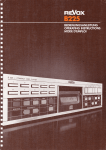
BEDIENU NGSAN LEITUNG
REVOX 8251 INTEGRATED AMPLIFIER
WICHTIGE HINWEISE
Schützen Sie lhr Gerät vor übermässiger Hitze
und Feuchtigkeit. Stellen Sie es so auf, dass die
Lüftungsschli?e nicht verdeckt werden. Damit
die Kühlung der Endstufe optimal gewährleistet
ist, darf der Verstärker nur in horizontaler Lage
betrieben we rden. Vor Ansch essen des G erätes
an das Ne? sind unbedingt die Hinweise in Kapitel 1.3 zu beachten.
Ii
GARANTIE
Den Geräten. welche in der Bundesrepublik
Deutschland verkauft werden. liegt eine spezielle Garantieanforderungskarte bei. Entweder befindet sich die Karte in der Verpackung oder in
einer Plastiktasche an der Verpackungsaussenseite. Sollte diese Karte fehlen. wenden Sie sich
an lhr REVOX-Fachgeschäft oder an lhre REVOXLandesvertretung.
Für in der Schweiz und Osterreich gekaufte Geräte gibt der Fachhändler die Garantiebescheinigung ab,
Bei den in Frankreich gekauften Geräten finden
Sie die Garantiekarte in der Verpackung. Diese
Karte muss von lhrem autorisierlen REVOXFachhändler vollständig ausgefüllt und unter-
schrieben werden.
Bitte beachten Sie, dass die Garantie nur im Verkaufsland gültig ist. Ausserdem machen wir Sie
darauf aufmerksam, dass die Garantie erlischt,
wenn am Gerät unsachgemässe Eingriffe oder
nicht fachmännische Reparaturen vorgenommen worden sind.
VERPACKUNG
Bewahren Sie die Originalverpackung auf. Beieinem Transpoft ist diese Spezialverpackung der
beste Schu? für lhr wertvolles Gerät.
Subject to change
Printed in Switzerland
by WILLI STUDER AG i0.18.6581 (Ed.1283)
Copyright by WILLI STUDER AG
CH -8105 Regensdorf-Zürich
INHALTSVERZEICH
N IS
Seite
3
Allgemeines
3
1.1 .1 S ignalquellen anschliessen
3
1.1.2 Lautsprecher anschl iessen
3
1.2
Spezielles
3
1.2.1 Fernsteuern eines REVOX-Tonbandgerätes über den Verstärker REVOX 8251 (Option)
3
1.2.2 P exig as-A bd ec kha u be
3
13 Verstärker an das Ne2 anschliessen.
3
1.4
lndexliste der Bedienungselemente
4
1.4.1 Bedienungselemente
4
1.4.2 Anschlussfeld
5
INBETRIEBNAHME
1.
1.1
I
I
GRUNDBEDIENUNG
Einschalten des Verstärkers 8251
2.1.1 Signalquellen-Wahl (MONITOR SELECTOR t31l bis [36])
2].2 Lautstärke einstellen
2.1.3 Balance
2.1.4 M ono-Stereo U mschaltung
2.1.5 -20 dB-Taste [30]
2.1.6 Signal zu den Tonbandausgängen wählen (Tasten RECORD OUTPUT [3] bis
2.2
Filter
2.3
Anzeigefeld l27l
2.3.1 Statische Vol umen-Anzei ge
2.3.2 Pegelanzeige
2.3.3 Ausgangsleistung
2.4
Bedienung mit der lnfrarot-Systemfernbedienung 8201
2.4.1 Verstärkerbedienung
2.4.2 Tonbandgerät-Fernbedienung (angeschlossen an Buchse t46l)
2.
2.1
PEGEL DER EINGANCT EINSTELLEN
3
Allgemeines
3.1
.
Tonband-Eingänge messen und einstellen
Vorgehen
33 Empfindlichkeit der restlichen Eingänge einstellen
3.3.1 Empfindlichkeit des Eingangs TUNER [50] einstellen
3.3 2 Empfindlichkeit des Eingangs PHONO t56l/t571 einstellen
333 Empfindlichkeit des Eingangs DISC [51] einstellen
334 Empfindlichkeit des Eingangs AUX [55] einstellen
Kontrolle nach Gehör
3.4
3.2
3.2.1
4.
4.1
t8l)
.
6
6
6
6
6
7
7
7
7
B
B
B
I
I
I
9
10
10
10
10
10
1
1
1
11
11
LAUTSPRECHER-UNDKOPFHÖRERAUSGANGEEINSTELLEN
Lautsprecherausgänge einstellen
Einschalt-Lautstärke einstellen
Lautsprecherausgang B einstellen
Kopfhörer-Betrieb
13
13
13
13
13
5.1
TECHNISCHER ANHANG
Mögliche Fehlerquellen
5.2
5.3
5.4
Zubehör
Technische Daten
Abmessungen
14
14
14
14
15
4.1
4.1
.1
.2
4.2
5
2
1 INBETRIEBNAHME
1.1
Allgemeines
Signalquellen anschliessen
Als Signalquellen werden sämtliche Geräte
1.1.1
bezeichnet, welche ein Tonsignal liefern, wie
P
latte nsp
i
e I e r, Tu ne r u
nd To n ba n d g e räte. To n -
bandgeräte sind allerdings Signalquellen und
Signalempfänger (für die Aufnahme), darum
muss das Tonsignal in beiden Richtungen angeschlossen werden.
Plattenspieler:
- Das Kabel (mit Cinch-Stecker) vom Plattenspieler am Eingang PHONO anschliessen.
Für Geräte mit Moving Magnet-Tonzelle
wird der Eingang MM t56l benutzt, für Geräte mit Moving Coil-Tonzellen der Eingang
MC l57l (nachrüstbare Option Best.
Nr.
78670)
- Die dünne Erdlitze mit dem abisolierten En-
de an der Schraubklemme [60] anschliessen (Sechskant-Mutter lösen. Litze darunterschieben und wieder festdrehen).
Tonband- und Kassettentonbandgeräte:
(2x Kabel CzC 210)
- Den Tonbandgeräte-Ausgang (OUTPUT)
mit dem Verstärker-Eingang TAPE 1 [49] lN
verbinden.
- Den Tonbandgeräte-Eingang (INPUT) mit
dem Verstärker-Ausgang TAPE 1 OUT [49]
verbinden.
- Falls noch ein zweites Tonband- oder Kas-
settentonbandgerät angeschlossen werden soll, kann dafür der Ein- und Ausgang
TAPE 2l49l verwendet werden.
AUXilliary:
- Dieser Eingang ist für zusätzliche Signalquellen bestimmt. Beispielsweise können
angeschlossen werden:
ein drittes Tonbandgerät (nur Wiedergabe)
Zweit-Tuner Tonsignal vom Fernseher etc.
MONITOR:
- An den Anschlüssen MONITOR lN [53] und
OUT [54] kann ein Equalizer dazwischengeschaltet werden. Dafür muss allerdings die
Verbindung Vorverstärker - Endstufe aufgetrennt werden. Mit einem dünnen Stift
kann der Schalter SEPARATED l52l durch
das Loch in der Rückwand gedrückt werden.
Achtung. Die weisse Buchse bezeichnet immer den linken und die rote Buchse immer
den rechten Kanal.
t57l
Compact
-
D isc
Plattenspieler: (Ka bel CzC 210)
DerAnschlussfüreinen CompactDisc Plattenspieler ist mit DISC [51] bezeichnet.
Tuner (Empfänger): (Kabel C2C 210)
- Den Tunerausgang (beim 8261. FIXED
OUTPUT) mit dem Verstärker-Eingang TUNER [50] verbinden. Falls noch ein zweiter
Tuner (Bsp Mittelwellen-Empfänger) angeschlossen werden sollte, so kann dafür der
Eingang AUX [55] verwendet werden.
1.1.2 Lautsprecher anschliessen
Es können zwei Lautsprechergruppen (Paare)
angeschlossen werden. Falls diese Möglichkeit ausgenuüt wird, sollte die meistbenutzte
Lautsprechergruppe an den Klemmen SPEAKERS A tb8l angeschlossen werden. Die
Zweitlautsprecher demzufolge an den Klemmen SPEAKERS B 1591.
Beim Anschliessen der Lautsprecher ist auf
richtige Phasenlage zu achten. Die schwarze
Klemme an der Lautsprecherbox muss mit
der schwarzen (Masse) des Verstärkers, die
rote mitder roten (heiss) Klemme desVerstärkers verbunden werden. Damit die Lautspre-
cherkabel nicht unnötige Dämpfung verursachen, sollten nur Kabelverwendetwerden deren Ouerschnitt mehr als 0,75 mmz beträgt.
Achtung:
Die schwarzen Klemmen sind die Lautsprechermasse und sollten nicht miteinanderverbunden werden. Die roten Klemmen dÜrfen
unter keinen Umständen mit einer anderen
Klemme verbunden werden.
1.3 Verstärker an das Netz anschliessen
Der Verstärker sollte mit dem für die örtliche
Ne?spannung richtigen Ne2teil ausgerüstet
sein. Sicherheitshalber empfiehlt es sich, zu
kontrollieren, ob die Spannungsangabe an
der Rückseite des Gerätes mit der örtlichen
Ne?spannung übereinstimmt. lst dres nicht
der Fall, so muss das Netteil bei lhrem Fachhändler oder bei der REVOX-Ver-tretung des
Verkaufslandes ausgewechselt werden.
l.2Spezielles
1,2.1 Fernsteuern eines REVOX{onbandgerätes ü ber den Verstärker REVOX 9251
(Option)
Es besteht die Möglichkeit, ein Tonbandgerät,
welches keinen eigenen lnfrarot-Empfänger
besitzt, über den Verstärker mit der lnfrarot-
Fernbedienung REVOX 8201zu bedienen. Da-
zu muss allerdings der Einbausatz Best. Nr.
78666 im Verstärker eingebaut sein, Das Kabel für die Laufwerkfernbedienung der Kassettenbandmaschine REVOX 8710 oder der
Bandmaschine REVOXBTT wird an der Buchse TAPE TRANSPORT B77lB71A 146l angeschlossen
Soll der Verstärker über das Kassettengerät
REVOX 8710 timergesteuert eingeschaltet
werden, so werden die Buchsen POWER ON
B7B0 (am Kassettengerät) und REMOTE POWER ON t45l am Verstärker mit dem Kabel
Best. Nr. 33209 miteinander verbunden.
1.2.2 Plexi g las-Abdeckhau be
Abnehmen:
- Haube an beiden Metall-Leisten halten und
nach vorne wegziehen.
Aufse?en:
- Haube an beiden Metall-Leisten halten,
schräg von unten unter das obere Bedienungsfeld einschwenken und festdrücken.
Der Verstärker wird durch einen M ikroprozessor gesteuert, welcher beim Anschliessen an
das Netz initialisiert. Schlechte lnitialisierung
äussert sich durch U nbedienbarkeit des Gerätes. ln diesem Fall das Gerät kurz vom Netz
trennen und wieder anschliessen.
t31l
l32l
tl
t34l I35l
volJr.iE
[171
-
[16] t15l n41
roNti coilrSci
raPE
2
t13l
t58l t5el t45l t46l
Dlsat
t33I
_^t^_
t36l
Alx
l2l
1.4
lndexliste der Bedienungselemente
1.4.1
Bedienungselemente auf der Frontplatte
A Allgemein
t1l
POWER/STAND BY' ON, Ein/Aus-Taste
des Verstärkers
LED für Anzeige folgender Zustände:
a) bei ausgeschaltetem, ans Netz angeschlossenem Gerät leuchtet sie als
STAND BY-Anzeige
b) bei eingeschaltetem Gerät, leuchtet
sie, wenn die Taste SUBSONIC [9]
gedrückt wurde
c) bei eingeschaltetem Gerät leuchtet
sie. wenn ein Eingang gewählt
wurde, bei welchem die Funktion
SUBSONIC abgespeichert wurde
SUBSONIC ON, Taste für SubsonicFilter
1]
TREBLE.
Tonblende für hohe Frequenzen
[1
BASS,
Tonblende für tiefe Frequenzen
[12]
[1 3] MODE, Mono-Stereo-Schalter
[14] BALANCE RIGHT, Taste für BalanceEinstellung rechter Kanal
l2l
i9l
[1
5]
E
m pfä nge rfenste r der I nf ra rot-Steue ru ng
l16l BALANCE LEFI, Taste für Balance-Ein-
stellung linker Kanal
7]
SPEAKERS, Lautsprechergruppen- und
[1
Kopfhörerschalter
[1 B] HEADPHONES, Anschlussbuchsen für
Kopfhörer (200 bis 600 Ohm)
[19] HEADPHONES, vierstufiger Schalter für
Lautstä rkenkorrektur der Kopfhörerausgänge
| 271 D
I
SP
LAY, m
u
l28l VOLUME -,
les Anzei gefeld
Taste für Lautstärkenabltifu
n
kti onel
schwächung
+, Taste für LautstärkenerVOLUME
[29]
höhung
t30l - 20 dB, Taste für Lautstärkenabschwächung um -20d8
[37] TONE CONTROL, Taste für Klangregelung ein/ausschalten
B Bedienungselemente MoNlToR SELECTOR
[10] PHONO, Umschalter für Kapazität des
Plattenspielereingangs und Wahl des
Movrng Coil-Eingangs (Option)
[31] TAPE 1, Ouellenwahl Tonbandeingang 1
l32l TUNER, Ouellenwahl Tunereingang
iSSl pHONO, Ouellenwahl Ptatrens[ietö.
eingang (in Verbindung mit Schalter
l34l TAPE 2, OuellenwahlTonbandeingang 2
[35] DISC, Ouellenwahl Compact-Disc
Plattenspieler
t36l AUX, Ouellenwahl Reserve-Eingang
PHONO t10l)
C Bedienungselemente RECORD OUTPUT
t3l
l4l
MONITOR, Taste für MonitorJunktion:
a) gedrückt : gewähltes Ouellensignal
an den Tonbandausgängen
b) gelöst : Ouellensignal für die Tonbandausgänge wird mit den Tasten
RECORD OUTPUT bestimmt
TAPE COPY, Taste für Überspielungen
von Bandgerät zu Bandgerät
t5l
t6l
t7l
tBl
TUN ER, Tonbandausgangssignal vom
Tuner-Elngang
DISC, Tonbandausgangssignal vom
Disc-Eingang
PHONO, Tonbandausgangssignal vom
Phono-Eingang
AUX, Tonbandausgangssignal vom
Aux-Eingang
D Bedienungselemente Anzeigefeld
[20] INPUT SENSITIVITY, Taste für Eingangsempfindl ichkeit einstel len
[21] SPEAKERS B SENSITIVITY Taste für
La utstä rke-U ntersch ed La utsp rechergruppeAzuBeinstellen
l22lPOWER ON VOLUME. Taste für maximale E nschalt-Lautstä rke ei nstel len
STORE.
Speichertaste für Funktionen
l23l
bis
l20l
l22l
l24l LEVEL DISPLAY, Taste für Pegelanzeige
des Tonband-Ausgangs am Display [27]
(Peak Program Meter)
i
i
[25] VOLUME DISPLAY, Taste für Volumenanzeige am Displav l27l (statisch)
t26l POWER DISPLAY, Taste für ausgesteuerte Leistung in Watt am Display l27l
(Peak Program Meter)
[27] DISPLAY Anzeigefeld zeigt den mit den
Tasten [24] bis [26] gewählten Modus
an
1.4.2 Anschlussfeld
[45] REMOTE POWER ON, Anschluss für
ti mergesteueftes Ferneinschalten des
Verstärkers durch das Kassettengerät
8710
[46] TAPE TRANSPORT 87718710,
Anschluss für Fernbedienung der Laufwerkfunktionen mit der nfrarot-Fernbedienung 8201 des Tonbandg erätsB77
oder des Kassettengeräts 8710 (Option)
[47] N eüanschluss-Buchse
[48] TAPE 2, Ein- und Ausgänge für Tonbandgerät 2
TAPE
1, Ein- und Ausgänge fur Ton[49]
bandgerät
l50l TUNER, Tuner-Eingang
[51] DISC, Eingang für Compact Disc
I
1
Plattenspieler
[52] SEPARATED, Trennschalter für die Verbindung Vorverstärker zur Endstufe
l53l MONITOR lN, Endstufen-Eingang
[54] MON ITOR OUT, Vorverstärker-Ausgang
t55l AUX, Hilfs-(Reserve) Eingang
[56] PHONO MM. Eingang für Plattenspieler
mit dynamischer Tonzelle (Moving Magnet)
[57] PHONO MC, Eingang für Plattenspieler mit
M oving Coi l-Tonzel len (O ption)
[58] SPEAKERS A, Anschlussklemmen für Lautsprechergruppe A
l59l SPEAKERS B, Anschlussklemmen für Lautsprechergruppe B
[60] Erdungsklemme für den Plattenspieler
2 GRUNDBEDIENUNG
21 Einschalten des Verstärkers 8251
-
-
Drücken derTaste POWER ON [1] oder einer MONITOR{aste
([31] bis [36]) schaltet das Gerät ein.
Wird das Gerät mit der POWER ON-Taste [1] eingeschaltet, so
wird der beim letztmaligen Betrieb gewählte Zustand eingesrellt. Einschalten mit einer MoNlToR-Taste ([31] bis [36]) bewirkt, dass der angewählte Eingang direkt durchgeschaltet
wird.
Die Lautsprecherausgänge werden erst nach einer kurzen
Verzögerungszeit eingeschaltet. Dadurch werden Knackgeräusche. welche den Lautsprechersystemen schaden könnten, vermleden.
Signalq uel len-Wahl
t31l bis [36] )
Selbstverständlibh kann auch nach dem Einschalten eine ande2.1.1
(
M O N ITOR S ELECTOR
l31l t32t
t331
t34l t35l
t36l
rll
IEV(IX
].*L::
f
---1
[:il
rolFt
acRfFor rÄp[,
Signalquelle eingestelltwerden. Die jeweiligenTasten [31] bis
[36] korrespondieren mit den entsprechenden Eingängen an
der Rückseite des Verstärkers.
TAPE 1 [31] : Signalvom Eingang TAPE 1 lN [49]
TUNER l32l : Signal vom Eingang TUNER [50]
PHONO [33] : Signal vom Eingang PHONO MM [56] oder
falls der Schalter PHONO [10] auf MC steht,
vom Eingang PHONO MC [57] (OPtion)
Die geforderte Kapazität der Tonzelle (Datenblatt der Tonzelle
konsultieren) sollte annähernd der Summe Kabelkapazität *
Schalterkapazität entsprechen.
re
t34l :
[35] ::
AUX [36]
TAPE 2
DISC
Signal vom Eingang TAPE 2lN [48]
Signal vom Eingang DISC l51l
Signal vom Eingang AUX [55]
2.1.2 Lautstärke einstellen
Taste VOLUME [25] drücken, dadurch ist der Display
Potentiometer-Anzei ge gescha ltet.
FEVOX
l27l auf
Nach Einschalten wird das Signal erst nach ca. 3 Sekunden
durchgeschaltet (Lautsprecherschutz). Dabei sind zwei Einschalt-Lautstä rken möglich:
- War die
letzte eingeschaltete Lautstärke höher als die pro-
grammierte Einschalt-Lautstärke (Programmierung siehe
4.1.1) so wird auf die Einschalt-Lautstärke zurück geschaltet.
-
Wurde der Verstärker vorher unter der Einschalt-Lautstärke
betrieben. wird die kleinere gewählt.
Gewünschte Lautstärke einstel len:
- Drücken der Taste [28] bewirkt Absenken der Lautstärke.
Drücken der Taste l29l erhöht sie
- Drücken dieserTasten auf der Seite mit einem Pfeil (( oder))
bewi rkt langsames Verändern, Drücken auf der Seite mit zwei
Pfeilen (( oder )) schnelles Verändern der Lautstärke.
2.tr.3 Balance
Die Balance wird mit den beiden Tasten BALANCE LEFT [16]
und RIGHT [14] eingestellt. Der Einstellbereich beträgt *3/
-10d8 und kann in 0.5dB-Schritten eingestellt werden. Dadurch ist eine genaue Anpassung des Klangbildes an den Raum
möqlich.
Antippen der Tasten bewirkt Verändern der Balance in kleinsten
Einzelschritten, dauerndes D rücken automatisches, schrittweises Verändern. solange die Taste gedrückt bleibt.
n1
2.1.4 Mono-Stereo Umschaltung
Mit dem Schalter MODE [13] wird bestimmt. ob das Eingangssignal auf Mono oder Stereo geschaltet ist.
2.1.5 -2OdB-Taste [3O]
Die Lautstärke kann durch Drücken derTaste -20dB [30] um
-20 dB abgeschwächt werden. Die Volumeneinstellung und die
Anzeige im Display 127)wud dabei nicht verändert. Nochmaliges Drücken dieser Taste hebt die Funktion wieder auf.
2.1.6 Signal zu den Tonbandausgängen wählen (Tasten RECORD OUTPUT [3] bis [B]
Mit diesen Tasten wird bestimmt, welche Signalquelle auf die
Tonbandausgänge (für Aufnahmezwecke) geschaltet ist. Die
eEvox
gewählte Slgnalquelle ist dabei immer auf beide Ausgänge
I
(TAPE 1 OUT und f APE 2 OUT) geschaltet. Dies ermöglicht das
Aufzeichnen eines Programms, während gleichzeitig ein zweites Programm über die Lautsprecherboxen abgehört wird.
Mit den Tasren RECORD OUTPUT ([3] bis [B]) wird die Signalquelle zu den Tonband-Ausgängen definiert. Dadurch kann
unabhängig von der über die Lautsprecher abgehörten Signalquelle eine andere auf ein Tonband überspielt werden.
Wird die Taste IVONITOR t3l gedrückt (darüberliegende LED
leuchtet), so wird der gleiche Eingang auf dieTonband-Ausgänge geschaltet, welcher mit den MONITOR SELECTOR Tasten
[31] bis [36] gewählt wurde.
]NFFARiC REMOTE
.
I.rE
:Äfe
f--lfi
1
rüNeF
C&MELTD
1[-:if---"1
sEtecicÄ_.+
r-:i; L;!. -l [" - ..IC.{]
1ttt
11-
'V
L::
SYS] FIü
rmNo
tt
tt
q|
Eine spezielle Funktion hat die Taste TAPE COPY [4].
Wird die Taste TAPE COPY [4] gedrückt, so kann, während beispielsweise Musik ab Plattenspieler gehört wird, ein Programm
1 auf Band 2 (und umgekehrt) überspielt werden.
von Band
t31 t4l t51 t61 l7t
I81
Vorgehen:
-
-
Bei beiden Geräten den Schalter MONITOR auf Tape stellen
(nur in dieser Position kann über den Verstärker das aufgenommene Signal <hinter Band> kontrolliert werden.
Am Verstärker Taste TAPE COPY [4] drücken.
Bandmaschine mit dem zu überspielenden Programm auf
Wiedergabe starten.
- Zweites Bandgerät auf Aufnahme starten.
- Falls die Oualität der Überspielung kontrolliert
werden soll,
muss mit den MONITOR SELECTOR Tasten TAPE 1 l31l oder
TAPE 2 [34] das Bandgerät, welches auf Aufnahme geschaltet ist. angewählt werden.
2.2 Klangregelung und Filter
2.2.1 Klangregelung
Mit den Potentiometern BASS [12] und TREBLE [11] kann der
Klang extrem fein verändert werden. Wenn beide Potentiometer
in Rechtsanschlag gedreht sind, entspricht der Frequenzverlauf
des Verstärkers genau den Anforderungen für die sog. Loud-
Unabhängig von der Überspielung kann irgend eine andere Signalquelle (Tuner, Plattenspieler etc.) über die Lautsprecher abgehört werden. Die Uberspielung wird dadurch nicht beeinflusst.
REVOX
INFBAFEO
-2CöB
tlpE 1
L;-r r;:r
-'t
I
I|NFF
RTrcTE CONTMLLEÜ SYSIEM
pFONC
r::ä'*t r-.,,-1
J
ness-Funktion.
Vorgehen:
-
Taste TONE CONTROL [37] drücken (LED leuchtet)
- Mit den Potentiometern BASS [12] und TREBLE [11] die gewünschte Tonfarbe einstellen.
- Mit der Tasre TONE CONTROL [37] kann die Klangregelung
ein- und ausgeschaltet werden.
t37l
t12l
nlI
f-----l
ll
2.2.2Filter
Um die wertvollen Bass-Systeme der Lautsprecherboxen vor
berlast durch Verzerrung bei tiefen Frequenzen mit hoher Am-
Ü
plitude zu schützen, besteht die Möglichkeit, ein SUBSONIC Fil-
ter [9] zuzuschalten.
olche Tiefstfrequenzen treten vor allem bei Plattenspielern auf
Das Subsonicfilter kann aber jedem Eingang zuprogrammiert
werden (siehe Kapitel 3.3.2).
S
.
2.3 Anzeigefeld [27]
Das Anzeigeleld l27l des Verstärkers 8251 ist universell verwendbar. Es kann für folgende Funktionen umgeschaltet wer-
NEVOX
den:
'L Statische Volumen-Anzeige
2. Spitzenspannungs-Anzeige des Record Output-Zweiges
3. Ausgangsleistung in Watt
t241 12511261
2.3.1 Statische Vol umen-Anzeige
- Taste VOLU N/E [25] drücken, die Anzeige zeigt das eingestellte Volumen an. Der angezeigte Wert ist jederzeit reproduzierbar
Diese Anzeige ist auch bei ausgeschaltetem Gerät immer
sichtbar. lm ausgeschaltetem Zustand wird die Einschaltlautstärke angezeigt (programmierbar siehe Kapitel 3).
2.3.2 Pegelanzeige
-
Durch Drücken derTaste LEVEL [24] kann im Anzeigefeld der
Pegel am RECORD OUTPUT (Tonbandausgänge TAPE 1 und
2) abgelesen werden. Dies wird vor allem für Eich- und Kontrollzwecke gebraucht (siehe Kapitel 3)
B 251
.
INTEGRATED AMPLIFIER
I
B
I
!
L
B 251
.
NTFGRATED AMPL|FIER
t
2.3.3 Ausgangsleistung
-
Durch Drücken der Täste POWER 126l zeigt die Anzeige die
momentane Ausgangsleistung des Verstärkers an.
Da die Anzeige Spitzenspannungen misst. muss sie auf den
relativ grossen Bereich von 0,01 bis 200 Watt geeicht sein.
Wenn man die Anzeige bei einem dynamischen Musikprogramm beobachtet, fällt auf, dass schon bei einer mittleren
D urchschn ittsla utstä rke Pegelspitzen bis zu 1 OO Watt mögl ich
sind. Diese Spitzen belasten natürlich die Lautsprecherboxen,
darum sollten nur solche verwendet werden. welche die
maximale Last ohne Schaden zu nehmen vertragen.
Achtung: Die Leistungsangaben unterhalb des Displays [27lbeziehen sich auf Lautsprechersysteme mit 4 Ohm lmpedanz. Für
Systeme mit B Ohm halbieren sich die Angaben.
2.4 Bedienen mit der
lnfrarot-Systemfernbedienung
8201
Der Verstärker 8251 kann über die lnfrarot-Systemfernbedienung drahtlos fernbedient werden. Uber das obere Tastenfeld
des Fernbedienungs-Kästchens wird der Verstärker angesteuert.
Die Revox-Systemfernbedienung 8201 ist dafür ausgelegt, die
komplette Revox H i-Fi Kette (Tuner, Verstärkel Kassetten-/Bandgerät und Plattenspieler) fernzubedienen. Entsprechende Hinweise sind der Bedienungsanleitung zur Fernbedienung B201 zu
entnehmen. Die Geräte empfangen die Befehle von der Fernbedienung am sichersten. wenn die Fernbedienung gegen das zu
steuernde Gerät gerichtet ist.
2.4.1 Verstärkerbed ienu ng
Verstärker einschalten:
er Ve rstä rker wi rd d u rch ei ne Ouel lenwahltaste ( MO N ITO R)
eingeschaltet.
Lautstärke verändern:
Drücken derTaste - senkt die Lautstärke. mitTaste * wird sie
D
angehoben.
Taste -20dB senkt die Lautstärke um 20d8.
Balance:
MitdenTasten BALANCE L und R kann die Balance im Bereich
von +3/-10 dB verändert werden.
Tonband-Ausgänge:
Mit derTaste REC OUT:MON kann das Ouellensignal auf die
Tonband-Ausgänge geschaltet werden.
Verstä rker ausschalten:
Mit der Taste POWER OFF (rechts unten) werden die fernsteuerbaren Geräte ausgeschaltet.
2"4.2 Tonbandgerät-Fernbedienung (angeschlossen
an
Buchse [46])
Ein Tonbandgerät ohne eigenen lnfrarot-Empfänger kann an
Buchse TAPE TRANSPORT Bl7lB7'10 angeschlossen werden
(nachrüstbare Option). Die entsprechenden Bedienungselemente sind im unteren Tastenfeld zu finden.
B 251
.
INTEGFATED AMPLIFIEF
r
L
3
PEGEL DER EINGANGE EINSTELLEN
3.l Allgemeines
Die Eingänge des Verstärkers REVOX 8251 können individuell
jeder Signalquelle angepasst werden. Ab Werk sind sie auf den
Nominalwert (siehe Daten) eingestellt. Falls beim Umschalten
von einem Elngang zu einem anderen starke Lautstärkeunterschiede hörbar sind (vergleichen bei lauten Musikstücken).
müssen die Eingänge neu eingestellt werden.
Dazu müssen als erster Schritt die Tonbandeingänge gemessen
werden. Um bei Tonbandkopien höchste Bedienungssicherheit
zu gewährleisten, sind die Tonbandausgänge des Verstärkers
kreuzverschaltet. Bedingt dadurch misst die interne MessSchaltung die Summe beider Ausgänge. Darum darf nur ein
Eingang nach dem anderen gemessen werden. da ber gleichzeitigem Betrieb beider Tonbandgeräte ein falscher Wert abgelesen wird. Zur Sicherheit darf nur das Tonbandgerät eingeschaltet sein, dessen Signal gemessen wird. Wenn die Tonbandeingänge gemessen und aneinander angepasst worden sind, kann
einer der beiden als Vergleichsreferenz zur Eichung der restlichen Eingänge verwendet werden.
Falls kein Tonbandgerät angeschlossen wird, kann die meistverwendete Signalquelle (Tuner, Plattenspieler etc.) als Vergleichsreferenz verwendet werden. Der ganze Abschnitt 3.2 kann übergangen werden.
Das Subsonic-Filter zum Schutz der Lautsprechersysteme vor
Verzerrun g bei Tief st-Frequenz-l m pu lsen (Taste
S U BS O N
I
CON
[3]) kann jedem Eingang zuprogrammiert werden. Sinnvoll ist
es besonders für die PHONO-Eingänge. Aus diesem Grunde
wird der Programmiervorgang nur im Abschnitt <Empfindlichkeit des Eingangs PHONO einstellen> erklärt. Für die Funktion
TAPE COPY kann das Subsonic-Filter nicht verwendet werden.
DieTasten [20] bis [22] aktivieren Funktionen mitwelchen man
Einstellungen umprogrammieren kann. Will man die Einstellung
nicht ändern. nur kontrollieren. so kann die Funktion durch er-
neutes Drücken der entsprechenden Taste wieder gelöscht
werden.
3.2 Tonband-Eingänge messen und einstellen
Bemerkung: Die meisten Kassetten- und Spulentonbandgeräte
besitzen Ausgangspegelregler. Für den folgenden Abgleich
werden diese benötigt. Machen Sie sich darum mit deren Bedienung vertraut. Vorgängig zu der folgenden Einstellung sollte
kontrolliert werden, ob die Tonbandeingänge (am Verstärker)
auf mittlere Empfindlichkeit eingestellt sind (Tasten SENSITIVITY INPUT [20] und VOLUME [25] drücken, wechselweise die
Monitor-Tasten TAPE 1 [31] und TAPE 2 [34] drücken. Dabei
muss der blinkende Punkt im 12.Feld der Anzeige stehen. Korrektur mit den Tasten [28] und [29], Abspeichern durch D rücken
der Tasre sToRE [23]).
3.2.l Vorgehen
-
Tonband-Eingang 1 anwählen (Taste TAPE 1 [31] drücken).
Tonband 1 einschalten und auf Wiedergabe starten (Prog ram
m-M ateria l: optima I ausgesteuerte Auf nahme m it lauten
Passagen).
-
Am Verstärker Tasten SENSITIVITY INPUT [20] und LEVEL
[24] drücken.
Die Ausgangspegelregler am Tonbandgerät so einstellen,
dass die Anzeige am Verstärker bei den lautesten Passagen
0dB gerade erreicht.
- Tonbandgerät 1 ausschalten und mit dem zweiten Gerät die
gleiche Einstellung vornehmen.
Ausnahme:
Falls ein Tonbandgerät (oder beide) nicht mit Ausgangspegelreglern ausgerüstet ist, wird dieses (oder das meistgebrauchte)
als Vergleichsreferenz betrachtet.
3.3 Empfindlichkeit der restlichen Eingänge einstellen
Es ist wichtig, dass alle Signalquellen ungefähr das gleiche Pro-
gramm-Material wiedergeben (bsp. klassische Musik. laute
Passagen).
10
t20l
l27l
l23l t24l
t2e1
3.3.1 Empfindlichkeit des EingangsTUNER [5O] einstellen
- Taste Tuner [32] drücken.
- Am Tuner REVOX 8261 die Taste CAL 4OOHz (Kalibrierton)
drücken.
-
-
l24l und INPUT [20] drücken.
Mit den Tasten VOLUME [28] und [29] den Eingangspegel auf
den Referenz-Wert im Display [27] einstellen.
Taste STORE [23] drücken, dadurch ist die Empfindlichkeit
des Tuner-Eingangs abgespeichert.
Tasten LEVEL
3.3.2 Empfindlichkeit des Eingangs PHONO [56]/[57] einstellen
- Taste PHONO [33] drücken.
- Schalter PHONO [10] auf eine der drei Eingangskapazitäten
einstellen (siehe Kapitel
2.1.1).
- Laute Passagen einer Platte abspielen.
- Tasten LEVEL [24] und INPUT [20] drücken.
- Mit den Tasten VOLUME [28] und [29] auf den Referenz-Wert
-
im Display [27] einstellen.
Taste STORE [23] drücken, die Empfindlichkeit des Plattenspieler-Eingangs ist eingespeichert.
Falls ein Tuner ohne Kalibriertaste angeschlossen wird (2.B.
REVOX 8760). muss ein Programm mit lauter Musik (Fortissimo-Passagen abwarten) eingestellt werden. Diese Musik so
genau als möglich auf den gleichen Pegel wie Eingang TAPE einstellen.
Moving Coil Eingang [57] (Option)
-
Schalter PHONO [10] auf MC stellen.
Gleiches Vorgehen wie vorgängig beschrieben.
Bei den Plattenspieler-Eingängen empfiehlt es sich, gleichzeitig
zu der Eingangsempfindlichkeit auch das Subsonic-Filter miteinzuspeichern. Dadurch werden die Lautsprechersysteme vor
Uberlast durch tiefste Rumpelfrequenzen geschützt.
- Empfindlichkeit wie vorgängig beschrieben einstellen.
- Taste SUBSONIC ON t3l drücken (LED 2 leuchtet).
- Taste STORE [23] drücken.
Hinweis:
t2l
trEvox
IH'FAFIO
-t
ll
-
trd!1
r-----'t
faE
1
lux€n
Es kann je eine Einstellung für den MM- und MC-PHONO-E|n-
t3I
gang definiert werden.
FFMTE
F!üo
l--1 r:--1 l---1
;----MONrrSe SEieatoR+
I
[=r;--1eel
r:AFF
2
OLSC
AUX
3.3.3 Empfindlichkeit des Eingangs DISC [51] einstellen
-
Taste DISC 135l drücken.
-
den Referenz-Wert am Display [27] einstellen.
Taste STORE f23l drücken.
- Fortissimo-Stelle auf einer Compact Disc anwählen.
- Taste LEVEL 124) und INPUT [20] drücken.
- M it den Tasten VOLUM E [28] und [29] das Eingangssignal
3.3.4 Empfindlichkeit des Eingangs AUX [55] einstellen
Dieser Eingang wird auf die gleiche Art wie der Tuner-Eingang
eingestellt (siehe 3.3.1).
auf
3.4 Kontrolle nach Gehör
Auf die vorgängig beschriebene Art sind die Eingänge sehr genau einstellbar. Man kann selbstverständlich die Eingänge auch
nach dem Gehör einstellen, doch muss beachtet werden, dass
der Mensch Musikmaterial mit verschiedenen Frequenzen unterschiedlich laut empf indet. Dies erschwert es, Musik zuverlässig auf Lautstärkenunterschiede zu beurteilen.
Durch direktes Vergleichen der Eingänge kann die Einstellung
kontrolliert werden. Bedingung ist jedoch. dass alle Eingänge
mit dem gleichen (oder wenigstens mit einem ähnlichen) Tonoder Musikstück beurteilt werden.
11
Vorgehen:
B 251
- Tasten VOLUME [25] und INPUT [20] drücken.
- Ab Tonband für die Einstellung geeignete Musik abspielen.
-
-
.
INTEGRATEIJ AMPLIFIEF
Dieser Eingang wird als Referenz benötigt.
Tasten VOLUME [25] und INPUT [20] drücken.
Durch abwechslungsweises Drücken der Referenztaste und
der nächsten Eingangstaste den Pegel vergleichen und bei
Bedarf nach Gehör mit den Tasten VOLUME [28] und [29]
*uri*
'
";r-':.." ;'
]m 200
,
r
leicht korrigieren.
Achtung: Die Position des Balkens
in der Anzeige zeigt nicht
die Lautstärke des Signals an. Er ist lediglich eine lnformation,
wle stark das Signal verstärkt/abgeschwächt werden muss,
um den gleichen Ausgangspegel zu erreichen.
Falls der blinkende Punkt rechts oder links in die Endposition
gerät, so ist keine weitere Verstärkung resp. Abschwächung
mehr möglich.
-
Falls eine Korrektur notwendig war. muss die Einstellung neu
abgespeichert werden.
Dazu muss allerdings die Eingangswahltaste des zu programmierenden Eingangs gedrückt sein.
Taste STORE [23] drücken, die neue Einstellung ist eingespei-
chert.
Auf diese Art können sämtliche Eingänge kontrolliert und ggf
auf gleiche Pegel eingestellt werden.
12
4
LAUTSPRECHER- UND KOPFHORERAUSGANGE EINSTELLEN
4.1 Lautsprecherausgänge
einstellen
Die Lautstärke der Lautsprecherausgänge kann für zwei Betriebs-Arten eingestellt werden.
- Einschalt-Lautstärke
- Lautstärkenunterschied Lautsprechergruppe A zu
4.1.1
B
Einschalt-Lautstärke einstel len
-
Taste [22] (VOLUME POWER ON) drücken.
ln der Anzeige erscheinen zwei Felder. Die blinkenden Punkte
-
zeigen die programmierte Einschalt-Lautstärke an.
Mit den Tasten VOLUN/E [28] und [29] die beiden Balken in
der Anzeige auf die gewünschte Einschalt-Lautstärke einstel-
B 251
.
INTEGRATED AMPLIFIFR
t
len.
-
-
Taste STORE [23] drücken, die Anzeige wechselt. die gewünschte Einschalt-Lautstärke ist somit eingespeichert.
Falls die bestehende Einstellung nicht verändert werden soll.
nochmals Taste POWER ON VOLUME [22] drücken und der
Wert bleibt unverändert erhalten.
4.1.2 Lautsprecherausgang B einstellen
- Schalter SPEAKERS [17] auf B stellen.
- Taste SPEAKERS B [21] drücken.
VO- Gewünschten Lautstärken-Unterschied mit den Tasten
LUME [28] und [29] einstellen (Mitte des Balkens : 1 :1)
- Taste STORE [23] drücken. damit ist die Einstellung eingespeichert.
Wenn der Schalter SPEAKERS [17] wieder auf A gestellt wird,
läuft der Verstärker wieder mit der ursprünglich eingestellten
Lautstärke. Wird der Schalter auf Position A + B gestellt, wird
die niedrigste Lautstärke eingestellt. Dadurch ist der Schutz eines ev. schwächeren Lautsprecherpaares gewährleistet.
Achtung: Die Einschalt-Lautstärke ist auf -54d8 begrenzt.
Dieser Wert kann nicht unterschritten werden.
B 251
.
INTEGRAIED AMPLIFIER
r
Achtung; Falls zwei Lautsprechergruppen bei maximaler Lautstärke betrieben werden sollen. mussen B-Ohm Lautsprecherboxen verwendet werden.
4.2 Kopfhörer-Betrieb
-
REVOX
Schalter SPEAKERS [17] auf PHONES ONLY stellen.
Kopfhörer an Buchse [18] einstecken und mit den Tasten [28]
oder [29] die gewünschte Lautstärke einstellen. ln dieser Position des Schalters SPEAKERS [17] wird nur die Lautstärke des
Kopfhörerausgangs verändert. Wird der Schalter SPEAKERS
auf eine Lautsprechergruppe geschaltet, so bleibt die Lautstärke für die Kopfhörerausgänge gespeichert.
Bei gleichzeitigem Betrieb von Kopfhörer und Lautsprecherboxen (Schalter SPEAKERS ['17] auf Position A/B oder A + B), kann
die Lautstärke des Kopfhörerausgangs noch mit dem vierstufigen Schalter [19] verändert werden.
l17l
IJ
5
TECHNISCHER ANHANG
5.1 Mögliche Fehlerquellen
Bevor ein Defekt im Gerät vermutet wird, sollte man sich zuerst
vergewissern, ob das Anschliessen und die Bedienung. wie in
der Anleitung erklärt, durchgeführt wurde.
Mögliche Fehlerursachen;
- Verkabelung kontrollieren
- lst der Schalter SEPARATED
-
-
(Geräterückseite) gedrückt oder
gelöst
lst der Lautsprecherwahlschalter auf der richtigen Position
lst die richtige Ouelle angewählt
Verstärkung zu klein. ist die Taste -20d8 gedrückt
Klang verzerrl, ist die -20 dB-Taste gedrückt und der Verstärker trotzdem auf sehr hohe Lautstärke eingestellt
Eingang PHONO keine Wiedergabe. ist der Schalter PHONO
[10] auf Position MC oder auf der entsprechenden Kapazität
Wenn sich das Gerät nicht mehr bedienen lässt,'Netzstecker
kurz ausziehen und wieder einstecken (Prozessor Reset).
5.2Zubehör
Fernbedienung 8201 Best Nr. 31201
Einbaukit 8251 IR-TAPE REMOTE KIT Best. Nr. 78666
Einbaukit MC-Eingang Best. Nr. 78670
Einbaukit MM-Eingang Best. Nr. 78668
Kabel REMOTE POWER ON Best. Nr. 33209
Cinch Kabel 1m C2C 210 Best. Nr.33041
Cinch Kabel 2m C2C 220 Best. Nr. 33042
Winkel für Montage in 19"-Rack Best. Nr. 34100
5.3 Technische Daten
lmpulsleistung:
2 x
150W an 8 0hm 2 x 300W an 4 Ohm
Sinusleistung:
2x
100W an 8 0hm 2 x 150W än 4 Ohm
Nennleistung:
2x
100W an 4 0hm, beide Kanä e ausgesteued
Dämpfungsfaktor:
70 bei
Eingänge
TUNERI
160 mV...2,3 V,
AUX:
160
1
nominell 500 mV/47 kOhm
mV
2,3 V,
nominell 500 mV/47 kOhm
160 mV...2,3 V,
DISC:
nominell 500 mV/47 kOhm
TAPI
160 mV...2,3 V,
1
nominell 500 mV/47 kOhm
160 mV ..2,3 V,
nominell 500 mV/47 k0hm
nom. 700 mV/47 k0hm
TAPE 2
EXT. FILTER
PHONO MC
100 prV ..1,2 mV,
nominell 300 pVl100 Ohm
1,6 mV.. 23 mV,
nominell 5 mV/47 kOhm,z
68 pF . 400 pF
PHONO MM
TAPt
100
1:
TAPt 2:
100
TAPE COPY
EXT. FILTTR
KOPFHÖRER (2
Klangreglen
mV
1,7 V,
nominell 500 mV/)10 k0hm
Bass:
Höhen
X):
mV
1,7 V,
nominell 500 mV/)10 kOhm
nominell 500 mV/)10 kOhm
nominell 700 mV/)10 k0hm
L5V max. (bei 100W/4Ohm),
regelbar in 4 Stufen *4,0, -4, -8
lz/.l12 dB . . -12 dB
l5klz/-11 dB .. 7 dB
3A
zwischen
90 dB
kHz)
75 dB
Übersprechen
Eingängen: (bei 10 kHz)
Kanaltrennung: (bei 1
c ba '
.20klz:+0/-02d8
Frequenzgang:
2ANz
Phono RlAA-Entzeftung:
(4 Ze tkonstanten)
+0,3
Harmonische Verzerrung:
0,01% bei Nennie
(
dB
stung
0,01% bei 50 mW
bei 10 kHz)
Ansteigszeit:
2psmt4OhmLast
Allgemeines
Betriebsbedingungen:
Leistungsaufnahme:
l{
etz-Ferneinschaltung:
Umgebungsiemperatur 5o...40o, re ative Luft
feuchtigkeit Klasse F
max. 650 W
vom Cassettenrecorder 8710 über 6-pol ge Buchse
Speicherinhaltr
ber Stromausfa I ble bt der Speicherinhalt erhalten
Optionen:
PHON0 l'4C E ngang
TAPE TRANSPORT REIVOTE B1] /B7TA
Gewieht:
8,5 kg
Abmessungen:
BxTxH (mm)
450x332x153
Anderungen vorbehalten
14
anr
(Hochpege e ngänge, bezogen auf 500 mV,10 kOhm
Abschluss)
96dB bei Nenn e stung 80dB be 50mW
(Phono IVM Erngang, bezogen auf 5 mV,1 kOhm
Abschluss)
75dB bei Nenn estung 75dB be 50mW
äquiva ente Fremdspannung am frngang -124 dBV
kHzl4 0hm
EmplindlichkeiVlmpedanzr
Ausgänge
Pegel,/zulässige Last:
l8 Hz. 18 dB 0lrave / ed"r Q re le zup'og
Subsonic-Filter:
5.4 Abmessungen {mm)
normale Ausführung
I
EEETI] EEE
ll
::::
I E:EE
l-l
-
-L
EEIEEIEEIE
-l
ee oQc=r:oooo
+
Einbauversion für 19"-Rack (Einbau nur horizontal)
EE€F
(o
o
EIFEETC]EE
r-]
EIEfEIEIEIFE
ee oo-rr-roooo
15
OPERATI NG INSTRUCTIONS
REVOX 8251 INTEGRATED AMPLIFIER
IMPORTANT
Protect your amplifier from excessive heat and
humidity. lnstallthe ampllfier in a location where
the ventilating louvres are not obstructed. To ensure proper cooling of the power stage, the amplifier must only be operated in horizontal position. Please read the instructions in Section 1.3
carefullv before connecting the amplifier to an
AC supply.
GUARANTEE
A special guarantee request card is bypacked for
all amplifiers sold within the Federal Republic of
Germanv. This card is either located inside the
packing or in a plastic pouch on the outside.
Should this card be missing. please consultyour
REVOX dealer or your national REVOX distributor.
For amplifiers sold in Switzerland and Austria.
the guarantee card is issued directly by the dealer.
Amplifiers sold in France have a guarantee card
inside the packing. This card must be completly
filled out and signed by your authorized REVOX
dealer.
Please note thatthe guarantee is onlyvalid within
the country in which the equipment has been
sold. The guarantee becomes null and void if
modifications or repairs have been made by incompetent persons.
PACKING
Please save the original packing material. This
special packing provides optimum protection for
your valuable equipment.
TABLE OF CONTENTS
Page
3
STARTUP
3
3
Connecting the audio
3
ConnectinÖ tne
3
Special
(option)
3
Remote control of a REVOX tape recorder through the REVOX 8251 amplifier
3
Acrylic plastic
3
Connecting the amplifier to the AC
PROCEDURE
1.
1.1 General
sources
1.1.1
speakers
1.1 .2
inslructions
1.2
.2.1
cover
1.2.2
supply
1.3
4
controls
1.4 lndex of o[erator
4
1.4.1 Front-panel controls
5
1.4.2 Connector panel
.
6
2. BASIC OPERATING PROCEDURES
6
2.1 Switching on the 8251 amplifier
6
2.1.1 Selecting the audio sources (MONITOR SELECTORS t31l through t36l)
6
2.1.2 Volume control
6
2.1.3 Channel balance
7
2.1.4 Mono/stereo change-over
7
2.1.5 -20 dB button t30l
2.1.6 Selecting the audio source for the tape outputs (RECORD OUTPUT buttons [3]
....... 7
through t8l)
7
filters
Tone
control
and
2.2
B
2.3 Display l27l
B
2.3.1 Static volume indication
B
2.3.2 Peak level indication
I
2.3.3 Output power indication
9
2.4 Operating with the infrared system remote control 8201 .
I
2.4.1 Remote control of amplifier
(connected
to socket t4Ql)
9
2.4.2 Remote control of tape recorder
10
3. ADJUSTING THE SENSITIVITY OF THE INPUTS
0
3.1 General
10
3.2 Calibrating and adjusting the tape inputs
10
3.2.1 Procedure
10
3.3 Adjusting the sensitivity of the remaining inputs
. 11
3.3.1 Adjusting the sensitivity of the TUNER input t50l
11
3.3.2 Adjusting the sensitivity of the PHONO inputs t56l/i571
11
3.3.3 Adjusting the sensitivity of the DISC inputs [51]
11
3.3.4 Adjusting the sensitivity of the AUX inputs t55l
11
3.4 Checking by ear
13
4. ADJUSTING THE SPEAKER AND HEADPHONES OUTPUT VOLUME
13
4.1 Adjusting the speaker output volume
13
4.1.1 Adjusting the power-on volume
13
4.1.2 Adjusting speaker output B .
13
mode
4.2 Headphones
14
5. TECHNICAL APPENDIX
..... 14
5.1 Troubleshooting
....... 14
5.2 Accessories ...
14
5.3 Technical Data
15
5.4 Dimensions
1
1
....
2
1 SIART-UP PROCEDURE
1.1
General
1.1.1
Gonnecting the audio sources
Audio sources are devices such as turntables,
tuners, and tape recorders that supply audio
signals. Tape recorders can both transmit and
receive (record) signals whrch means thatthe
audio path must be connected in both directions.
Turntable:
-
-
Reel-to+eel and cassette record ers (2x cables
c2c
2101
- Connect recorder output (OUTPUT) to amplifier inputTAPE 1 lN 1491.
- Connect recorder input (INPUT) to amplifier
-
output TAPE 1 OUT i491.
A second reel-to-reel or cassette recorder
can be connected to the input and output
TAPE
Connect cable (Cinch connector) of the
turntable to the PHONO input. lf the turntable is equipped with a moving magnet
cartridge, the input MM 156l is used. Turntables with moving coil cartridges are connected to the input MC [57] (retrofittable
option. part No. 78670).
Connect the skinned end of the thin ground
wire to the screw-type terminal [60] (loosen
hexagon nut, slide stranded wire under it
and retighten nut).
2l4gl.
AUXiliary:
- The AUX input is available for connecting
additional audio sources. The following
can, e.g. be connected:
third recorder (reproduce only), second
tuner, audio signal of TV set, etc.
MONITOR:
- An equalizer can be looped in between the
terminals MONITOR lN [53] and OUT [54]
after the connection between preamplifier
and the power stage has been separated.
This can done by pressing the switch SEPARATED l52l with the aid of a thin pin that is
inserted through the hole in the rear wall.
Note: the white socket always identifies the
left-hand channel. the red socket the righthand channel.
t57I
[56]
1.1.2 Connecting the speakers
To pairs of speakers can be connected. The
speakers that are used more frequently
Compact Disc digital audio player (cable C2C
210)
- The socket for connecting
a CD digital audio player is labeled with DISC [51].
Tuner (cable C2C 210)
- Connecttuner output lfor8261: FIXED OUTPUT) to the amplifier input TUNER 1501.
A second tuner (e.9. AM receiver) can be
connected to the AUX input t551.
should be connected to the terminals SPEAKERS A [58], the second pair to the terminals
SPEAKERS B l59l
Ensure that speakers are connected in correct
phase relationship. The black terminal on the
speaker box must be connected to the black
(ground) terminal of the amplifier the red
speaker terminal to the red (hot) terminal of
the amplifier. To prevent undesirable speaker
1.3 Connecting
cable attenuation, these cables should have a
more than
conductor cross-section
0.75 mmz.
of
the amplifier to the
AG
supply
The amplifier should be equipped with a power supplythat matches your local line voltage.
P ease verify that the volta ge specif icati ons on
the rear panel of the amplifier conform to your
local line voltage. Should this not be the case,
the power supply must be replaced by your local dealer of the country in wich the unit was
sold.
I
Caution.
The blackterminals arethe speakergroup and
should not be interconnected. Under no circumstance maythe red terminals be connected to a different terminal.
1.2 Special
instruction
control of a REVOX tape
recorder through the REVOX 8251 ampli-
1.2.1 Remote
fier (option)
Tape recorders that are not equipped with an
infrared receiver can be controlled remotely
through the amplifier from an infrared remote
control REVOX 8201.ln this case retrofit kit
No. 78666 must be installed on the amplifier.
The remote-control cable for the tape transportfunctions of the cassette recorder REVOX
8710 or the reel-to-reel recorder REVOX 877
is to be connected to the socketTAPE TRANSPORT 87718710 146l
The amplifier can also be powered on under
control of the timer in the cassette recorder
REVOX 8710.ln this case the socket POWER
ON B7B0 (on the cassette recorder) and the
socket REMOTE POWER ON t45l on the amplifier are interconnected with the cable No.
33209
1.2.2 Acrilic
Removal:
plastic cover
- Hold cover on its two metal strips and remove it by pulling forward.
lnstallation:
- Hold cover on its two metal strips, position
lower edge at an angle below upper group
of controls and snap it on.
The amplifier is controlled by a microprocessor which initializes itself when the amplifier is
connected to the AC supply. lncorrect initialization manifests itself by leaving the amplifier
in inoperative condition. Should this happen,
briefly disconnect the amplifier from the AC
supply and reconnect it.
t30l t3r1 132'J t33l
trll
t37t t34l t351 t36l
tl5l
tl3I
[14]
t58l
112l
tsel t45l t46l
t4eI
1481
1.4
lndex of operator controls
1.4.1 Front-panel
controls
A General
t1l
POWER/STAND BY'ON, on/off button
of amplifier
12) LED for signaling the following conditions:
a) Amplifier connected to AC supply
but switched off. LED is on as a
STAND BY indicator
b) Amplifier switched on: LED is on if
SUBSONIC l9l has been pressed
c) Amplifier switched on: LED is on if
an input has been selected for which
the SUBSONIC function has been
stored
SUBSONIC ON, button for activating
subsonic filter
TREBLE,
tone control for high frequen[1 1]
tgl
CICS
[12] BASS. tone control for low frequencies
[13] MODE, mono/stereo selector
[14] BALANCE RIGHT, button for balancing
right-hand channel
[15] Receiver window of infrared control
[16] BALANCE LEFI, button for balancing
left-hand channel
speaker pair and headSPEAKERS,
[17]
phones selector
[18] HEADPHONES, socket for connecting
headphones (200 to 600 ohms)
HEADPHONES,
4-step switch for
l19l
controlling the headphones volume
[27] DISPLAY, multifunction display window
[28] VOLUME -, button for decreasing
volume
+, button for increasing
VOLUME
[29]
volume
t30l -20 dB, button for decreasing volume
by -20 dB
[37] TONE CONTROL, button for enabling/
bypassing tone control
B MONITOR SELECTOR controls
[10] PHONO, change-over switch for capacitance of turntable and selection of
moving coil input (option).
[31] TAPE 1, source selection: tape input 1
t32l TUNER, source selection: tuner input
t33l PHONO, source selection: turntable (in
conjunction with switch PHONO [10])
l34l TAPE 2, source selection: tape input 2
[35] DISC, source selection: Compact Disc
digital audio player
t36l AUX. source selection: auxiliary input
C RECORD OUTPUT controls
t3l
14)
MONITOR, button for monitor function:
a) pressed selected source signal
available at tape outputs
b) released source signal available
at tape outputs is determined with
setting of RECORD OUTPUT buttons
TAPE COPY, buttons for tape-to-tape
copylng
:
:
t5l TUNER, tape output signal from
TUNER input
t6l DISC, tape output signal from
DISC input
l7l PHONO, tape output signal from
PHONO input
tBl AUX, tape output signal from
AUX input
D Display controls
[20] INPUT SENSITIVITY, button for adjusting input sensitivity
[21] SPEAKERS B SENSITIVITY, button for
compensati ng vol ume difference
between speaker pair A and B
l22lPOWER ON VOLUME, button for
adjusting maximum volume after amplifier is switched on
[23] STORE, store button for fonctions [20]
to l22l
124) LEVEL DISPLAY, button for indicating
tape output level on display l27l @eak
program meter)
[25] VOLUME DISPLAY. button for indicating volume on displaV 127) (static)
DISPLAY, button for indicating
POWER
[26]
power
in Watts on display [27]
driven
(peak program meter)
[27] DISPLAY, indicates the values selected
with buttonsl24) through [26]
1.4.2 Connector panel
[45] REMOTE POWER ON, socket for timercontrolled remote power-on of amplifier via cassette recorder 8710
[46] TAPE TRANSPORT 87718710, socket
connecting the tape transporl remote
control of the reel-to-reel recorder 877
or the cassette recorder 8710 in conjunction with the infrared remote control 8201 (option)
1471 AC power inlet
[48] TAPE 2, inputs and outputs for tape
recorder 2
l49l TAPE 1, inputs and outputs for tape
recorder 1
[50] TUNER. tuner input
[51] DISC, input for Compact Disc digital
audio player
[52] SEPARATED. isolating switch for opening
the connection between preamplifier and
power stage
[53] MONITOR lN. input of power stage
[54] MONITOR OUT, preamplifier output
t55l AUX, auxiliary input
156l PHONO MM, input for turntables equipped
with moving magnet cartridge
[57] PHONO MC, input for turntables equipped
with moving coil carlridge (option)
[58] SPEAKERS A, terminals for speaker pair A
[59] SPEAKERS B, terminals for speaker pair B
[60] Ground terminal for turntable
2
BASIC OPERATING PROCEDURES
2.1 Switching on the 8251 amplifier
Press POWER ON button [1] or one of the MONITOR buttons
([31] trough [36]) to switch the amplifier on.
- When the amplifier is switched on with POWER ON [1], the
last operating condition is automatically reestablished. lf one
of the MONITOR buttons ([31] trough [36]) is pressed, the se-
-
-
t33l
t34l t35l
t36l
rll
lected source is connected through.
The speaker outputs are only enable after a brief delay in order
to prevent damage to the speaker system from switching
IEVOX
clicks.
2.1.1
t31l t32l
Selecting the audio sources (MONITOR
SELECTORS
[31] trough [36])
A different audio source can be selected at any time after the
amplifier has been switched on. The selection buttons [31]
r t_l
rä
fur:
roNf t)crdnor JA4,
through [36] activate the corresponding outputs on the rear panel of the amplifier.
TAPE 1 t31l : signalfrom inputTAPE 1 lN [49]
TUNER l32l : signal from input TUNER [50]
PHONO [33] : signal from input PHONO MM [56] or from
input PHONO MC [57] (option) if the PHONO
switch [10] is in the MC position
The required capacitance of the cartridge (refer to specifications of the cartridge) should be approximately equalto the sum
of the cable capacitance and the switch capacitance.
t34l :
[35] ::
AUX [36]
TAPE 2
DISC
signal from input TAPE 2 lN t48l
signal from input DISC [51]
signal from input AUX [55]
2.1.2 Volume control
Press button VOLUME [25]. The display
to potentiometer
indicaiion.
l2Tlwill be switched
R'VOX
n
':<
ThespeakeroutpUtSareenabledwithadelayofapproximatelywltruH=ffiF
.i ,; ;
'L:rra.,
3 seconds (speaker protection). Two volumes are possible after
the amplifier has been switched on:
- lf the last volume selected was higher than the programmed
power-on volume (for programm ing refer to Section 4.1.1). the
volume is reduced to the power-on volume.
- lf the amplifier was previously operated below the power-on
volume. this lower volume is selected.
-
'!'LUi'-
Adjusting the volume:
-
The volume can be reduced by pressing button [28] or increased by pressing button [29].
The volume changes slowly if one of the buttons is pressed on
the side with one arrow (( or )) and quickly if pressed on the
side with two arrows (( or )).
2.1.3 Channel balance
The channel balance is adjusted with the two buttons BALANCE
LEFT [16] and RIGHT [14]. The range of adjustment is +3/-10 dB
and can be varied in steps of 0.5 dB. The sound pattern can thus
be accurately adjusted to the acoustics of the room. Brlef touching of the buttons adjusts the balance in one 0.5 dB step, other-
wise the balance is automatically corrected step-by-step for as
long as the button is held.
t14l
raFE?
2.1.4 Mono/stereo change-over
The MODE selector [13] determines wether the input signal is
switched to mono or stereo mode.
2.1.5 -2OdB button [30]
The volume can be reduced by -20 dB by pressing button [30].
The volume setting and the indication in the display [27] will not
change. This function can be cancelled by pressing the button
agarn.
2.1.6 Selecting the audio source for the tape outputs (RECORD OUTPUT buttons [3] through [B])
These buttons select the signal source that is to be connected to
the tape outputs (for recording purpose). The source is always
connected to both outputs (TAPE 1 OUT and TAPE 2 OUT). A
programm can be recorded while llstening to a second program
over the speakers.
When the N/ONITOR [3] button is pressed (LED above is on),
the same input is connected to the tape outputs that has been
selected with the MONITOR SELECTOR buttons [31] trough
I
qd/ox
-t
I
J
INTRARED REMOT€
iiirEl
-l)d8
tuNe!
l&TrcLLE5
FtsoNo
r--r r-- | r:-a r---"1
SYSIEM
r-t
tt
II
; -._-MOS:iCF SE.rriCR+
r.1 1üa|;1
{; 1 ,'ll-r;
laPtz
Drill
roNt *clllQo.
Jol.
When the button TAPE COPY [4] is pressed, a program can be
copied f rom tape 1 to tape 2 or vice versa while simultaneously
listening to a different source, e.g. a record being played.
Procedure:
*
-
Set MONITOR switch to tape on both units (only in this position can the recorded signal be checked through the amplifier.
Press TAPE COPY [4] on amplifier.
Start recorder containing the source tape in play mode.
Start second tape deck in record mode.
To monitor the quality of the copy, select the tape deck that
operates in recording mode by pressing either MONITOR SELECTOR button TAPE 1 [31] or TAPE 2 [34].
l3l
t41
tst 16l t7l
t8l
A different audio source (tuner, turntable. etc,) can be connected to the speakers while copying from tape to tape without interfering with the copy tunction.
2.2Tone control and filters
2.2.1 Tone
control
Extremelyf ine adjustment of the sound color is possible with the
potentiometers BASS [12] and TREBLE [11] When both potentiometers are in the right-hand limit position, the frequency response is compensated according to the loudness function.
NEVOX
l
INFFARFD
Idg
C-;:f
:ar',e
1
rm:
iVNL:3
REMüE C'NTrcIED
tsSNO
C#- l l;;il;
stt;roe,-,+
! - ,-üorirrtF
t'-?*tr
- tr?-'l
2
cila
roN! iioilInol
ralE
al,x
Procedure:
- Press TONE CONTROL [37] (LED turns on)
- Adjust for the desired sound color with the potentiometers
-
BASS [12] and TREBLE [11].
The tone control can be enabled/bypassed by pressing the
TONE CONTROL button [37].
[37]
t12l
nll
[:
SYSTEM
2.2,2Filters
ln order to prevent overloading of the expensive bass system in
the speaker boxes from high-amplitude distortions at low frequencies, a SUBSONIC filter [9] can be cut in. Such extremely
low frequencies (rumble) are mainly produced by turntables.
However, the subsonic filter can be programmed for any source
(refer to Section 3.3.2)
2.3 Display [27]
The display l27l of Ihe 8251 amplif ier can be switched over bet-
' lifa,:ir'li:i:r
{:1f:
ri,
i,
]rEVOX
ri
ween the following functions:
1 , Static volume indication
2. Peak level indication for the record output path
3. Output power in Watts
l24t t25lt26l
2.3.1 Static volume indication
- Press VOLUME button [25]:the display now indicates the volume setting. The indicated value can be reproduced at any
B 251
.
INTEGRATED AMPLIFIER
time.
The power-on volume is displayed when the amplifier
I
II
is
switched off (for programming refer to Section 3.).
2.3.2 Peak level indication
-
The level at the REPRODUCE OUTPUT (tape outputs 1 and 2l
can be read off by pressing the LEVEL button [24]. This func-
L.
B 251
.
INTFGRA-|ED AMPLIFIFR
<.j
[*
tion is primarily used for calibration and checking functions
(refer to Section 3.).
I
L
c
100
200
2.3.3 Output power indication
-
When the POWER button [26] is pressed, the momentary output power of the amplifier is displayed.
Since this instrument measures peakvoltages, it must be calibrated for the relatively wide range of 0.01 to 200 Watts. As
can be seen on the display, peak levels of up to 100W are possible in a dynamic music program even at medium volume
settings. The speakers must, of cours, be able to handle such
peaks which means that only those types of speakers should
be connected that can the maximum load without suffering
damage.
Note: the power specifications below the display [27) refer to
speaker systems with an input impedance of 4 ohms. These values must be cut in half for B ohm systems.
2.4 Operating with the infrared system remote control
8201
The 8251 amplif ier can be controlled remotely without cable by
using the infrared system remote control. The amplifier is controlled with the top group of buttons on the remote control box.
The REVOX 8201 system remote control is designed for controlling the entire Revox hi-fi chain (tuner, amplifier. cassette/tape
recorders and turntable). Additional information can be found in
the operating instructions of the B201 remote control. Commands are best received when the remote control box is pointed toward the unit to be selected.
2.4.1 Remote control of the amplifier
The amplifier is switched on by pressing one of the source selection buttons (MONITOR).
Volume control:
The volume is reduced by pressing the - button and increased by pressing the + button.
The -20d8 button reduces the volume by 20d8.
Balance:
The channel balance can be adjusted between +3/-10dB
with the buttons BALANCE L and R.
Tape outputs:
The source signal can be connected to the tape outputs by
pressing REC OUT:MON.
Amplifier power off:
The POWER OFF button (lower right) switches off allremotely
controllable units.
2.4.2Remote control of tape recorder (connected to socket
t46l)
A tape recorder without built-in infrared receiver can be connected to the socketTAPE TRANSPORT Bl7lB710 (retrof ittable
option). The corresponding controls are located in the lower
group.
B 251
.
INTEGRATED AMPLIFIEaI
t
3
ADJUSTING THE SENSITIVITY OF THE INPUTS
3.1 General
The input of the REVOX 8251 amplifier can be individually
matched to any audio source. The factory adjusts all inputs to
the nominal values (refer to specification sheet). lf pronounced
volume differences occur when switching from one input to
another (compare with a loud passage), the inputs should be
readjusted.
The tape inputs should be measured first. To ensure maximum
operating safety when making tape copies, the tape outputs of
the amplifier are cross-connected. The internal measuring circuit therefore measures the sum of both outputs. This means
that only one input after the other should be measured because
an incorrect value would be obtained if both tape units were simultaneously in operation. Only the tape recorder from which
the signals are measured should be switched on. After the tape
inputs have been measured and matched to each other, one of
the two can be used as a rererence for calibrating the other in-
lf no tape recorder is connected. the most frequently used audio
source (tuner. turntable, etc.) can be used as the reference and
Section 3.2 can be skipped in its entirety.
The subsonic filter which protects the speaker systems from
distortions occuring from rumble pulses (SUBSONIC button [3]
pressed), can be program assigned to any input. lt is especially
useful for PHONO inputs. For this reason the programming procedure is only explained in the section'Adjusting the sensitivity
of the PHONO input". The subsonic filter cannot be used for
TABE COPY function.
Buttons [20] trough [22] activate functions with which settings
can be reprogrammed. lf the settings only need to be checked
rather than reprogrammed. the function can be cancelled by
pressing the corresponding button again.
puts.
3.2 Calibrating and adjusting the tape inputs
Note: most reel-to-reel and cassette recorders are equipped
with an output level control. You should be familiar with its operation. Before the subsequent adjustments are performed. ensure that the tape inputs (on the amplifier) are set to medium
sensitivity (press buttons SENSITIVITY INPUT [20] and VOLUME [25] and alternately the monitor buttons TAPE 1 [31] and
f APE2[34]. The f lashing dot should be in the 12th position of the
display. Correct with buttons [28] and [29] and save the setting
by pressing the STORE button [23]).
3.2.1 Procedures
- Select tape input 1 (press TAPE 1 [31]).
- Switch on tape recorder 1 and start in play mode (program
material: optimum recording level with loud passages).
- Press the amplifier buttons SENSITIVITY INPUT [20] and
LEVEL [24].
- Adjust output level control of tape recorder in such a manner
that the loudest passages produce a 0 dB reading on the amplifier display.
- Switch tape recorder 1 off and repeat the foregoing steps with
the second recorder.
Exception:
lf one (or both) recorders are not equipped with an output level
control, use this (or the most frequently used unit) as the refer-
ence for comparison.
3.3 Adjusting the sensitivity of the remaining inputs
It is important that all audio sources reproduce approximately
the same program material (e.9. loud passages of classical
music).
10
t20l
l27l
l23l I24l
3.3.1 Adjusting the sensitivity of the TUNER input [50]
- Press TUNER [32].
- Press CAL 400H2 button (calibration tone) on the REVOX
8261 tuner.
- Press buttons LEVEL l24l and INPUT [20].
- PTessVOLUME buttons [28] and [29]toadjustthe inputchannel to the reference value in the display [27].
- Press STORE button [23]. The sensitivity of the tuner is now
When connecting a tuner that does not feature a calibration
tone button (e.9. REVOX 8760), a program with loud music
(wait for fortissimo passages) should be selected. Adjust this
music as accurately as possible to the same level as the TAPE in-
put
stored.
3.3.2 Adjusting the sensitivity of the PHONO inputs
[56]/
t57l
-
Press PHONO button [33].
Set PHONO switch [10] to one of the three input capacitances
(refer to Section 2.1.1).
Play loud record passages.
Press buttons LEVEL 124) and INPUT [20].
Press VOLUME buttons [28] and [29] to adjust to the reference value on the display 127).
Press STORE button [23]. the sensitivity of the phone input is
now stored.
Moving coil input [57] (option)
- Set PHONO [10] switch to MC position.
-
Repeat foregoing procedures.
It is recommended to program-assign the subsonic filter to the
phono inputs in order to protect the speakers from overloads
caused by rumble frequencies.
- Adjust sensitivity as outlined above.
- Press SUBSONIC ON t3l (LED 2 turns
- Press STORE button [23].
on).
Note: lndividual sensitivities can be programmed for the MM
and the MC input.
nEvox
j
>
I
I
lr r,itf
INTRAqFD
Ft
_ä)dti
raPEr
tU\EF
RffOIE
r-:r r-=r r.-l r---l
I r--' --rr--=--t r- -r t-;-'l
I
MlN
lalNt:
i:oilrRcl
raiE
?
PhÖ^_O
f,F 5L-uL')c
95c
3.3.3 Adjusting sensitivity of the DISC input [51]
- Press DISC button [35].
- Select fortissimo passage on a Compact Disc.
- Press buttons LEVEL l24l and INPUT [20].
- Press VOLU M E buttons [28] and [29] to adjust the input signal
-
3.3.4 Adjusting the sensitivity of the AUX input [55]
This input is adjusted in the same manner as the tuner input.
(Refer to Section 3.3.1).
to the reference value on the display {27).
Press STORE button [23].
3.4 Checking by ear
The inputs can be accuratly adjusted by following the procedures outline above. The inputs can also be checked by ear however, it shoud be noted that music material with different frequencies are perceived differentls by the human ear. This makes
it diffrcult to JUdge level differences in music.
The settings can be checked by direct comparison of the inputs.
However, all inputs should be checked wlth the same (or at least
similar) sound of music passages.
Procedure:
-
B 251
Press buttons VOLUME [25] and INPUT 1201.
Play a piece of music from that is suitable for making adjustments.
This input is used as the reference.
Press buttons VOLUME [25] and INPUT [20].
Alternately press the reference button and the next input button to compare the level and adjust by ear as required by
.
INTFGRATED AMPLIFIEN
r
t_
pressing the VOLUME buttons [28] and [29].
Note: the position of the illuminated bar on the display does
not indicate the level of the signal. lt is an indication of how
much the signal must be amplified/attenuated in order to obtain the same output level.
lf the flashing dot moves to the left- or right-hand limit position,
no further amplification/attenuation is possible.
12
- lf a correction was necessary. the setting
-
must be newly
stored.
Ensure that the selection button of the input to be reprogrammed is pressed.
Press STORE button [23]. The new setting is now stored.
All inputs can be checked and readjusted to the same level by
following this procedure.
4 ADJUSTING
THE SPEAKER AND HEADPHONES OUTPUT VOLUME
4.1 Adjusting the speaker output volume
The volume on the speaker outputs can be adjusted
rating modes:
- Power-on volume
- Volume difference between pairs A and
4.1.1
-
-
-
-
B
Adjusting the power-on volume
Press POWER ON VOLUME button [22].
Two fields appear on the display The flashing dots indicate
B 251
.
INTEGRATED AMPI IFIFR
the programmed power-on volume,
Press VOLUME buttons [28] and [29] to move the two bars in
the display to the desired power-on volume.
Press STORE button [23]. The display changes over and the
desired power-on volume is now stored.
lf the existing setting is to be retained, press the POWER ON
VOLUME button [22] again.
4.1.2
-
fortwo ope-
Adjusting speaker output B
Set SPEAKER switch [17] to B.
Press button SPEAKERS B [21].
Adjusting volume difference with VOLUME buttons [28] and
[29] (center of bar : 1 :1).
Press STORE button [23]. The setting is now stored.
wArs
),1 1
10
Note: The power-on volume is limited
cannot be exceeded.
a 251 . JNTEGRATED
1m2m
to -54d8.
t
This value
AMPLIFIER
wAfrs
When the SPEAKERS switch [17] is set back to A, the amplifier
operates with the original volume setting. lf the switch is set to
position A + B. the amplifier operates with the lower of the two
volumes in order to protect speakers that may have a lower
music power rating.
o.ü
0,o1
0.1 1
10
lm 20
Note: lf two speaker pairs are operated simultaneously at maximum level, all boxes must have an impendance of B ohms.
4.2 Headphones
-
Set SPEAKER switch [17] to PHONES ONLY
Plug headphones into the front-panel socket [18] and adjust
the desired volume with button [28] or [29]. ln this setting of
the SPEAKERS selector [17], only the volume of the headphones output is affected. The volume on the headphones
output is stored as soon as the SPEAKERS selector is
switched back to one of the speaker settings.
I
I
L
With the headphones and the speaker boxes (SPEAKER selector [7] in position A/B orA + B), the volume on the headphones
output can still be varied with the 4-step switch [19].
IJ
5
TECHNICAL APPENDIX
5.1
Troubleshooting
Before concluding that the amplrfier is defective, ensure that all
connections and operating procedures conform to the instruc-
tions of this manual.
Possible trouble sources:
- Check cabling
- ls the SEPARATED switch (rear panel) pressed or released?
- ls the speaker selector in the correct position?
- Has the correct source been selected?
- Gain too low: is the -20dB button pressed?
- Sound distorted: is the -20 dB button pressed and the amplifi-
-
5.2 Accessories
Remote control 8201, part No. 31201
8251 IR-TAPE REMOTE KlT, part No. 78666
MC input retrofit kit. part No. 78670
MM input retrofit kit part No. 78668
REMOTE POWER ON CABLE, part No. 33209
Cinch cable 1 meter C2C 210, part No. 33401
Cinch cable 2 meters C2C 220, part No. 33042
Brackets for 19" rack mounting, part No. 34100
er set for very high output volume?
No output f rom PHONO input: is the PHONO switch [10] in M C
position or the corresponding capacitance?
lf the amplif ier can no longer be operated, disconnect amplifier from AC supply and reconnect it to force reinitialization of
microprocessor.
5.3 Technical data
0hms
0hms
2 x 300W into 4 Ohms
Music Power:
2x
150W nto
Sinus:
2 x
100W into B
Gontinuoussinewavepower:
2x 100W into 4 Ohms, both channe s dr
Damping lactor:
100 at
lnputs
TUNER
1
B
2
terminat on):
ven
96dB re ative to nom na poweroutputB0dB at50mW
(Phono M M input, referred to 5 mV, 1 kOhm
i nation):
75 dB re ative to nom na power output 75 dB at 50 mW
eqrivaient noise vo tage at the input -124 dgV
te rm
160 mV . 2.3V,
nominal y 500 mV/47 kOhms
160 mV
AUX:
.
2.3 V,
nomrnally 500 mV.z47 kOhms
160 mV .. 2.3 V,
C.D SC;
nom na ly 500 mV/47 kOhms
160 mV...2.3 V,
TAPE 1:
T
Dtr
',
EXT. FILTER
PHONO MC
PHONO
TAPE
N4
[4
i:
nominally 500 mV/47 kOhms
160 mV...2 3 V,
nominal y 500 mV,z47 kOhms
nominal y 700 mV/47 kOhms
100
pV
1.2 mV,
nominally 300 pV.z100 0hms
1.6 mV...23 mV,
nom na ly 5 mV.z47 kOhms/
68 pF...400 pF
100 mV ...1.7 V,
nominally 500 mV/)10 kOhms
TAPE 2:
100 mV ...1.7 V,
nominaliy 500 mV/)10 k0hms
nominal y 500 mV/)10 kOhms
TAPt COPY
EXT. F
nominal y 700 mV/)10 kOhms
HEADPHONES (2 x):15V max. (at 100W/4 Ohms),
adjustable in 4 steps, t4, 0, -4, -8
LTIR
Tone control:
30Hz/I12
Bass:
Treb
e
15kHz/'|7
dB
...
dB
-I2
dB
-7 dB
Grosstalk between
inputs: (at 10 kHz)
Ghannel separation: (at
90 dB
1
kHz) 75 dB
Frequency response:
Phono RIAA
(4
t
?AH2'.20kHz
equalization: +0
+0/-02
dB
3 dB
me constants)
Total harmonic distortion:
0.01 % at nominal power
output
0.01 % at 50 mW
(at 10 kHz)
Rise time:
2 ps w
th
4
Ohms
oad
General
Operating Gonditions:
Amb ent temperature 5...40 centigrade relat ve
humidity c ass F
Power consumption:
max.650W
Remote power-onl
'o'n B7l0 Cassette Peco.de'v a 6-po p 'orrectot
nor volalie. maro y ra r-a ned wrll^ou pou"
Memory contents:
Options:
PH0NO MC-1nput
TAPF TRANSPORT REIV]OTE 81]
Weight:
8.5 kg (18 bs i2 oz)
Dimensions:
450x153x332
WxHxT(mm)
Sublect to change
14
18llz,18dB/0ctave(assignabletoeachprogramsource)
kHzl8 Ohms
SensitiYity,/l mpedance:
Outputs
Level,/permissible load:
Subsonicfilter:
x 150W into 4 0hms
/B]14
5.4 Dimensions (mm)
Standard version
::E:
lE:-r:l_J
lll
E€EfTfEEE
i-i
_f
ETSET:EET=
Qo.o::oooo
=l
I
Version for 19" rack installation (only in horizontal position)
I ll
EIEEEIEEE
Qo oQ
EEE:
l::::l_l
_
CIE]T]EIEIEIEI
j
5
Y
15
MODE D'EMPLOI
REVOX 8251 AMPLI FICATEUR NTEGRE
I
AVIS IMPORTANTS
Prot6gez votre appareil de I'humidit6 et de la
chaleur excessive. Placez-le de telle fagon que la
grille d'a6ration ne soit pas obtur6e. [appareil ne
doit fonctionner qu'en position horizontale pour
que le refroidissement soit optimal. Les indications du chapitre 1.3 seront imp6rativement lues
avant de raccorder I'appareil au secteur.
GARANTIE
Pour les appareils vendus en RFA, vous trouverez
soit ä I'int6rieur de I'emballage soit dans une pochette en plastique fix6e ä I'ext6rieur, un formu-
laire de demande de garantie. Si ce dernier devait manquer, votre fournisseur ou I'agent officiel
REVOX du pays d'achat se ferait un plaisir de
vous la procurer. Veuillez remplir düment ce formulaire et I'envoyer ä I'agence officielle REVOX
du pays d'achat.
Pour les appareils achet6s en Suisse ou en Autriche. l'attestation de garantie est d6livr6e par le
revendeur REVOX autoris6.
Pour les appareils vendus en France, vous trouverez la carte de garantie ä I'interieur de I'emballage. Cette cafte doit Ötre complÖt6e et sign6e
par votre revendeur REVOX agr66.
La garantie n'est valable que dans le pays oü a
lieu I'achat. Nous nous permettons de vous rendre attentif au fait que toute intervention non autoris6e ä l'int6rieur de I'appareil, nous libÖre de
toute obligation.
EMBALLAGE
Conservez l'emballage d'origine. Dans le cas
d'un transporl, il est la meilleure protection pour
votre appareil.
REPERTOIRE
1.
U:5,5,t,:ERVlcE
1.1
Raccordement des sources ...
Raccordement des haut-parleurs
Particularit6s ..
1.2.1 T6l6commande d'un magn6tophone REVOX par l'amplificateur REVOX 8251 (option)
1.2.2 Cache en plexiglas
Raccordement de l'appareil au secteur
1.3
1.4
lndex des organes de commande .....
1.4.1 Commandes de la face avant
1.4.2 Panneau de raccordement
1.1
.1
1.1.2
1.2
2.
2.1
2.1.1
2.1.2
2.1.3
2.1.4
2.1
.5
2.1.6
2.2
2.3
5
6
o
6
6
6
7
7
7
7
Afficheur l27l
B
B
B
2.4
Utilisation avec la t6l6commande infrarouge 8201
2.4.1 Utilisation de l'amplificateur
2.4.2 T6l6commande d'un magn6tophone (raccord6 ä la prise t46l)
REGLAGE DU NIVEAU DES ENTREES
G6n6ralit6s
Mesure des entr6es magn,6tophone
3.2.1 Processus
R6glage du niveau des autres entr6es
3.3.1 R6glage de la sensibilit6 de I'entr6e TUNER l50l
3.3.2 R6glage de la sensibilit6 de I'entr6e PHONO t56l/t571
3.3.3 R69lage de la sensibilit6 de I'entr6e DISC t51l
3.3.4 R6glage de la sensibilit6 de I'entr6e AUX t55l
Contröle ä l'6coute
3.
3.1
3.2
3.3
REGLAGE DES SORTIES HAUT-PARLEURS ET
R6glage des sorties
R6glage du volume ä la mise en
R6glage de la sortie haut-parleur
haut-parleurs
service
4.1.1
B
4.1.2
4.2 Utilisation des casques
5. ANNEXE TECHNIOUE
5.1 Causes possibles de pannes
5.2 Accessoires ...
5.3 Caract6ristiques techniques
5,4 Dimensions
.
2
4
4
UTILISATION DE BASE
Mise en service de I'amplificateur
Sel6ction des sources (MONITOR SELECTOR t31l ä t36l)
R6glage du volume
Balance
Commutation mono-st6r6o
Touche -20 dB t30l
S6lection du signal de sortie <enregistrement> (touches RECORD OUTPUT t3l ä t8l)
Correction de tonalit6 et filtre
2.3.1 Affichage statique de volume
2.3.2 lndication de niveau
2.3.3 Puissance de sortie
3.4
4.
4.1
3
3
3
3
3
3
CASOUES
I
I
I
9
10
10
10
10
10
11
11
11
11
11
13
13
13
13
13
14
14
14
14
15
1 MISE EN SERVICE
1.1
G6n6ralit6s
1.1.1
Raccordement des sources
Tous les appareils qui d6livrent un signal musi- Magn6tophqn_es ä bobines ou ä cassette. (2 x
cäble C2C 210)
cal, tels les tables de lecture, les tuners et
les
magn6tophones sont d6sign6s comme sourceslPar ailleurs, les magn6lophones sont ä
fois des sources et des r6cepteurs (pour
registrement) et possödent des coÄnections
da"ns les deux
- Raccorder la
Table de lecture:
- Connectez le cäble de la table de lecture
(6quip6 de prises Cinch) ä I'entr6e PHONO.
On utilisera I'entr6e MM t56l pour les appareils 6quip6s de phonocapteurs ä aimant
mobile. Les appareils 6quip6s de cellules ä
bobine mobile seront raccord6s ä I'entr6e
MC t571. (Option no.78670).
- [extr6mit6 d6nud6e du cordon de mise ä la
terre doit ötre fix6e par la borne ä vis [60]
(d6visser l'6crou ä six pans, introduire le cäble et revissefl.
-
la
l'en-
diiections.
-
sorlie _ dg. ltrgn6tophone
(OUTPUT) avec l'entr6e TAPE 1 lN [49] de
I'amplificateur.
Relier l'entr6e duJna^g.ng9P!9ry {INPU_T)
avec la sortie TAPE 1 OUT [a9] de l'amplificateur.
Pour le raccordement d'un deuxiöme magn6tophone, on utilisera la prise d'entr6e/
sorlie TAPE 2l4?l.
AUXiliaire:
- Cette entr6e est destin6e ä des sources suppl6mentaires. On peut par exemple y raccorder:
un troisiöme magn6tophone (en lecture
seulement), le signal audio d'un t6l6viseur,
etc..
.
MONITOR:
- On peut ins6rer un 6galiseur gräce aux prises MONITOR lN [53] etOUT [54]. Bien entendu, le pr6amplificateur et les 6tages de
puissance doivent ötre s6par6s dans ce cas,
ce qui s'effectue en appuyantsur le commutateur SEPARATED [52] avec une petite tige
ä travers le panneau arriöre.
Attention: La prise blanche d6signe toujours
le canal gauche et la rouge le canal droit.
t57l
156I
Lecteur de Compact Disc: (cäble C2C 210)
- Le raccordement avec un lecteur de Compact Disc est d6sign6 par DISC [51].
Tuner (R6cepteur radiophonique): (cäble C2C
210)
- Relier la sortie du tuner (FIXED OUTPUT
pour le 8261) ä I'entr6eTUNER l50l de l'amplificateur. Si on d6sire utiliser un deuxiöme
tuner (par ex. un r6cepteur pour ondes moyennes), on peut utiliser ä cet effet I'entr6e
AUX [55]
1.1.2 Raccordement des haut-parleurs
I I est possible de raccorder deux groupes (paires) de haut-parleurs. Dans un tel cas, on raccordera le groupe de haut-parleurs le plus utilis6 aux bornes SPEAKER A tb8l. Le deuxiöme
groupe de haut-parleurs sera par cons6quent
raccord6 aux bornes SPEAKER B t591.
Lors du branchement des haut-parleurs, on
veillera ä leur bonne mise en phase. La prise
noire de l'enceinte acoustique doit ötre reli6e
ä la borne noire (masse) de l'amplificateur, la
prise rouge ä la borne rouge de I'amplificateur
( si g nal) . Pou r 6viter toute att6nuati on ou perte
1.3 Raccordement de l'amplificateur au
due aux cäbles des haut-parleurs. on n'utilisera que des cäbles d'un diamötre sup6rieur ou
6gale ä 0,75 mm2.
Attention:
Les bornes noires sont la masse des haut-parleurs et ne doivent pas Ötre reli6es entre elles.
Les bornes rouges ne doivent en aucun cas
ötre reli6es ä d'autres bornes.
secteur
[appareil doit ötre 6quip6 d'une alimentation
correspondant ä la valeur locale du secteur.
Pour plus de süret6, on s'assurera que les indications de tension au dos de I'appareil correspondent ä la valeur locale du secteur. Si ce
n'est pas le cas, l'alimentation doit Ötre chang6e par votre revendeur ou par la repr6sentation REVOX du pays d'achat.
1.2 Particularit6s
T6l6com mande d'u n mag n6top hone
REVOX par I'amplificateur REVOX 8251
1.2.1
(option)
On peut t6l6commander un magn6tophone.
non 6quip6 d'un r6cepteur infrarouge, avec la
t6lecommande REVOX 8201 par I'intermediaire de l'amplificateur. Cela n6cessite I'installation du circuit no. 78666 dans I'amplificateur. Le cäble de commande du m6canisme
d'un magn6tophone ä bobine REVOX 877 ou
ä cassette REVOX 8710 estalors reli6 ä la prise
TAPE TRAN SPORT 877 18710 146).
Si I'amplificateur doit ötre mis en service par le
timer du magn6tophone ä cassette 8710, on
raccordera les prises POWER ON B7B0 (du
magn6tophone ä cassette) et REMOTE POWER ON t45l de I'amplificateur par le cäble
no. 33209.
llamplificateur.est command6 par un microprocesseur qui est initialis6 par le raccordement de l'appareil au secteur. Une mauvaise
initialisation se manifeste par l'impossibilit6
de se servir de I'amplificateur. On y rem6die
en deconnectant briövement I'appareil du
s6cteur.
1.2.2 Gache en plexiglas
D6pose:
- Tenir le cache par les deux moulures m6talliques et le tirer vers I'avant.
Pose:
- Tenir le cache par les deux moulures m6talliques, I'introduire obliquement sous le pan-
neau de commande sup6rieur et appuyer
fermement.
t281
t291
t30l t31l l32l
trt
[37] t34l t35l
IONE
l17l
t16l tl5t
CdTRÜL IAPEz
n41
t59l t45l [46]
l57l
OISC
t33l
_ l2l
t36l
__t
1.4
lndex d'organes de commande
1.4.1
Commandes de la face avant
A G6n6ralit6s
i1l
12)
POWER/STAND BY.ON, touche de
mise en service de I'appareil
LED indiquant les 6tats suivants:
a) lorsque l'appareil n'est pas en service
mais toutefois raccord6 au secteur,
elle indique le STAND BY
b) lorsque I'appareil est en service. elle
indique l'activation de la touche
suBSoNtc l9l
c) lorsque l'appareil est en service, elle
est illumin6e si une entr6e, ä laquelle
la fonction SUBSONIC e 6t6 affectu6e, est s6lectionn6e
SUBSONIC ON, touche du filtre subsonique
[1 1] TREBLE, correcteur d'aigus
[12] BASS, correcteur de graves
l1 3l MODE. commutateur mono/st6r6o
[14] BALANCE RIGHT, r6glage de ta batance
du canal droit
l9l
l15l fenötre du r6cepteur infrarouge de
la
t6l6commande
116l BALANCE LEFI, r6glage de la batance
du canal gauche
[17] SPEAKERS, commutateur des groupes
de haut-parleurs et casques
[18] HEADPHONES. prises pour le raccordement de casques (200 ä 600 Ohm)
[19] HEADPHONES, commutateur ä quatre
6tats pour la correction du niveau des
sorlies casques
i27l Dl SPLAY aflichage m ulti -fonctions
[28] VOLUME -, touche d'att6nuation de
volume sonore
[29] VOLUME +, touche pour l'augmentation du volume sonore
t30l -20dB, touche d'att6nuation -20d8
[37] TONE CONTROL, mise en/hors circuit
des correcteurs de tonalit6
B Commandes du MONITOR SELECTOR
[10] PHONO, s6lecteur de capacit6 de
I'entr6e pour table de lecture et s6lection de I'entr6e Moving Coil (option)
[31]TAPE 1, s6lection de I'entr6e magn6tophone 1
TUNER,
s6lection de I'entr6e tuner
l32l
l33l PHONO, s6lection de l'entr6e table de
lecture (en liaison avec le commutateur
[34] TAPE 2, s6lection de I'entr6e magn6tophone 2
DISC,
s6lection du lecteur de Compact
[35]
Disc
[36] AUX, s6lection de l'entr6e de reserve
PHONO [10])
C Commandes du RECORD OUTPUT
t3l
MONITOR, commande de la fonction
monitor:
a) activ6e signal source sur les sorties magn6tophone.
b) reläch6e signal sur les sorties
magn6tophone d6t6rmine par les
touches RECORD OUTPUT
14) TAPE COPY touche pour la copie d'un
magn6tophone vers I'autre
:
:
t5l TUNER, le signal du tuner est dirig6
vers les magn6tophones
t6l DISC, le signal du lecteur de Compact
Disc est dirig6 vers les magn6tophones
PHONO. le signal de I'entr6e phono est
17)
dirig6 vers les magn6tophones
tBl AUX, le signal de I'appareil auxiliaire
est dirig6 vers les magn6tophones
D Commandes de I'affichage
[20] INPUT SENSITIVITY, touche de 169lage
des sensibilit6s d'entr6e
[21] SPEAKERS B SENSITIVITY, touche de
r6glage de la diff6rence de volume
sonore entre les groupes de hautparleurs A et B
l22lPOWER ON VOLUME, r6slase du
niveau sonore maximal ä la mise en
service de l'appareil
[23] STORE. m6morisation des fonctions
120) ä l22l
124) LEVEL DISPLAY, commande I'affichage du
niveau des sorlies magn6tophone par le
display [27]
l25l VOLUME DISPLAY, commande l'affichage
sur le display l27l du r6glage du volume
sonore
t26l POWER DISPLAY, commande I'indication de
la puissance de sorlie en Watt sur le display
l27l (cröte-mötre).
[27] DISPLAY, I'afficheur indique le mode s6lectionn6 par les touches l24l ä 126l
1.4.2 Panneau de raccordement
[45] REMOTE POWER ON. prise pour la
mise en service de l'amplificateur command6e par le timer du magn6tophone
ä cassette 8710
TAPE
TRANSPORT 87718710, prise
[46]
pour la t6l6commande du m6canisme
d'un magn6tophone 877 ou 8710 par
la t6l6commande 8201 (option)
l47l Prise secteur
[48] TAPE 2. entr6es/sorlies pour le magn6tophone 2
TAPE
1, entr6es/sorties pour Ie magn6l49l
tophone 1
l50l TUNER, entr6e tuner
[51] DISC, entr6e pour le lecteur de Compact Disc
[52] SEPARATED, commutateur de s6paration entre le pr6amplificateur et les 6tages de puissance
t53l MONITOR lN, entr6e des 6tages de puisSANCC
l54l MONITOR OUI sorrie du pr6amplificateur
[55] AUX, entr6e auxiliaire (r6serve)
[56] PHONO MM, entr6e pour une table de
lecture 6quip6e de cellule ä aimant mobile
PHONO
MC, entr6e pour une table de
[57]
lecture 6quip6e de cellule ä bobines mobiles
[58] SPEAKERS A. bornes de raccordement pour
le groupe de haut-parleurs A
l59l SPEAKERS B, bornes de raccordement pour
le groupe de haut-parleurs B
Prise
de terre pour la table de lecture
[60]
2. UTILISATION DE BASE
2.1 Mise en service de l'amplificateur 8251
- Appuyez sur Ia touche POWER ON [1] ou sur l'une des touches
MONITOR (t311 ä t36l) et l'appareil se met en service.
- Si l'appareil est mis en service par la touche POWER ON l1l, il
se placera dans le dernier mode auparavant s6lectionn6. S'il
est activ6 par une touche MONITOR (t311 ä t36l). l'entr6e correspondante est directement s6lectionn6e.
- Les prises de sortie haut-parleur ne sont commut6es qu'aprÖs
un certain d6lai. Ceci 6limine tout risque de bruits de commutation qui pourraient nuire aux haut-parleurs.
2.1.1
S6lection des sources (MONITOR SELECTOR [31]
ä
t36l)
ll est bien sür possible de
s6lectionner une autre source aprÖs la
mise en service de l'appareil. Les touches t31l ä t36l correspondent aux entr6es du panneau de raccordement ä I'arrlÖre de
l'appareil.
TAPE 1 t31l : signal de l'entr6e TAPE 1 lN t491.
TUNER l32l : signal de l'entr6e TUNER [50].
PHONO [33] : signal de I'entr6e PHONO MN/ [56] ou. si le
commutateur PHONO [10] est positionn6 sur
MC, de I'entr6e PHONO MC [57] (option).
La somme de la capacit6 du cäble de liaison et de celle indiqu6e
par le s6lecteur doit autant que possible approcher la valeur nominale de la capacit6 de la cellule (voir caract6ristiques de
t31l t32t
t33l
t34l t35l
136l
rll
rEVOX
C;]
LrI:
roNr araninor
raFF 2
Ia
cellule).
t34l :
[35] ::
AUX [36]
TAPE2
signalde l'entr6eTAPE 2lN [48].
DISC
signal de l'entr6e DISC [51].
signal de l'entr6e AUX [55].
2.1.2R6glage du volume
Appuyer sur la touche VOLUME [25], l'aff icha ge 127) est alors
commut6 en indicateur de potentiomÖtre.
Le signal n'est commut6 qu'environ 3 seconds aprÖs la mise en
service de l'appareil (protection des haut-parleurs). Deux volumes sonores sont possibles ä la mise en service:
- Si le dernier volume sonore 6tabli 6tait sup6rieur ä la valeur
programm6e pour la mise en service (voir 4.1.1 pour la programmation), on se ramÖne automatiquement ä cette valeur
programm6e.
- Si le derniervolume sonore 6tabli 6tait inf6rieur ä la valeur programm6e pour la mise en service, la valeur la plus falble est
s6lectionn6e.
nEvox
tnl m
.?od
Iä[:c
Une pression sur le cöt6 de ces touches rep6r6 par une f lÖche
(( ou )) provoque une variation lente, une pression sur le cöt6
rep6r6 par deux flöches (( ou )) provoque une variation rapide du volume sonore.
2.1.3 Balance
La balance est 169l6e par les deux touches BALANCE LEFT [16]
et BALANCE RIGHT [14]. Le domaine de variation est de +3/1O dB et l'ajustement se fait par pas de 0,5 dB. On peut ainsi parfaitement adapter l'image sonore au local d'6coute.
Une courte pression sur ces touches provoque une varlation de
la balance par petits pas, une pression continue provoque une
variation par pas sucöessifs tant que la touche est maintenue
enfonc6e.
6
tl6I
r
!,..-M6Nil0
k_.rfFjf
INF
C'Ni'ROL
R6glage au volume sonore souhait6:
- Une pression sur la touche [28] provoque une att6nuation du
volume, une pression sur la touche [29] I'augmente.
-
TAPa
tt4l
n3l
IA4
2
I
2.1.4 Commutation mono-st616o
Le s6lecteur MODE [13] commute le signal d'entr6e en mono-ou
st616ophonie.
56lection du signal de sortie renregistrementr (touches RECORD OUTPUT t3l ä t8l)
Ces touches d6terminent quelle source est amen6e aux sorties
magn6tophones (afin d'6tre enregistr6e). La source s6lectionn6e est alors pr6sente sur les deux sorties magn6tophones (TAPE 1 OUT etTAPE 2 OUT). Cela permet l'enregistrement simultan6 d'un programme musical et l'6coute d'un second sur les enceintes acoustiques.
Les touches RECORD OUTPUT t3l ä t8l d6f inissent la source qui
est pr6sente sur les sorties magn6tophones. On peut ainsi, ind6pendamment de la source reproduite par les haut-parleurs, en
enregistrer une autre sur un magn6tophone.
Lorsque la touche MONITOR [3] est activ6e (la diode LED situ6e
au dessus est 6clair6e), la source pr6sente sur les sorties magn6tophones est celle s6lectionn6e par les touches I31l ä t36l
du MONITOR SELECTOR.
2.1.6
2.1.5 Touche
-2OdB
volume sonore peut ötre r6duit de 20 dB par pression sur la
touche -20d8 [30]. te r6glage du volume nominal et son affichage par le display [27] restent inchang6s. Une nouvelle pression sur cette touche ramöne le volume ä sa valeur ant6rieure.
Le
nEvox
INtsFAREO REMOTE CONIROLLED SYSIFM
-
-1
_Jll
vol !!1i
iarel
23.t1
ruN€t
pFoNo
f,mt.;-lfmLt
r--------1
lt
rl
; __MON|TOF sFrüCtöR+
r-*.,fifi:ffi[:1C?]
roN; (:$]itFor
La touche TAPE COPY [4] a une fonction particuliöre. Lorsque la
touche TAPE COPY [4] est activ6e, on peut, pendant l'6coute par
exemple d'un disque, copier une programme du magn6tophone 1 sur le magndtophone 2 (et vice-versa).
laFE
2
o{ril
aux
t3l t4t t51 t6t t7l
t8l
Processus:
-
Placer les s6lecteurs MONITOR des deux appareils sur TAPE
(c'est dans cette position seulement que le signal enregistr6
peut ötre contrö16 <aprös-bander).
Appuyer sur la touche TAPE COPY [4] de l'amplificateur
Placer le magn6tophone contenant le programme ä copier en
lecture.
- Placer le second magn6tophone en enregistrement.
- S i on veut v6rifier la qualit6 du transfert. il suffit de s6lectionner
la touche TAPE 1 [31] ou TAPE 2 [34] correspondant au ma-
gn6tophone commut6 en enregistrement.
2.2 Correction de tonalit6 et filtre
2.2.1 Correction de tonalit6
Les potentiomötres BASS [12] et TREBLE 111l permettent une
correction extrömement fine de la tonalit6. Lorsque ces deux
potentiomötres sont en but6e ä drolte, la 16ponse en fr6quence
de l'amplificateur correspond exactement ä la compensation
acoustique ( Loudness).
N'importe quelle autre source (tuner, tourne-disque. etc . . .) peut
ötre 6cout6e, ind6pendamment du transfert qui n'en est pas influenc6, sur les enceintes acoustiques.
NEVOX
INFFAB'D REMOTE CONIMLLEO SYSIAM
-23CU
-1
I
J
-
irj\€.
pFONO
m;: räf r:?:"1r=1 r-__-1
tt
F- -- r6tj:roa sEleaicq-
[:T-]2 r----1rc*l
-q
g:riri{l
t sa
alx
JAFF
Processus:
- Appuyer sur la touche TONE CONTROL [37] (la LED s'allu-
-
1Pa:1
me).
Etablir la tonalit6 d6sir6e avec les potentiomötres BASS [12] et
TREBLE [11].
Les correcteurs de tonalit6 peuvent ötre mis en/hors circuit
par la touche TONE CONTROL [37]
t37l
II
2.2.2Filtre
Les haut-parleurs de grave de vos enceintes acoustiques pour-
raient ötre d6t6rior6s par de trop fortes amplitudes ou distorsions du signal. Ceci peut ötre 6vit6 par le SUBSONIC Filter [9]
filtre. dont le röle est de supprimer les signaux de l'extröme grave, le plus souvent provoqu6s par les platines tourne-disques.
Ce filtre subsonique peut ötre affect6 par programmation
ä
chacune des entr6es (voir chapitre 3.3.2).
Rd/ox
2.3 Afficheur [27]
f afficheur l27l de l'amplificateur 8251 est d'un emploi universel. ll possöde les fonctions suivantes:
1. Affichage statique de volume.
2. lndication de la valeur de cr6te du niveau des sorties pour
l'en
registrement.
3. Affichage de la puissance de sortie en Watt.
l27l
2.3.1 Affichage statique du volume
- Appuvez sur la touche VOLUME [25]. l-affichage indique le
volume sonore 6tabli. La valeur indiqu6e est accessible ä tout
B 251
r
t24l 1251t261
INTEGRATED AMPLIFIER
Cet affichage est 6galement visible lorsque l'appareil n'esl
r*
I
plus en fonction. lJaffichage indique alors la valeur du volume
programm6e pour la mise sous tension (voir chapitre 3 pour Ia
t-
moment.
I
programmation).
2.3.2 lndication du niveau
-
Le niveau des sorties RECORD OUTPUT (sorties TAPE 1 et 2)
est aff ich6 lorsque la touche LEVEL [24] est activ6e, ceci prin-
cipalement ä des fins de r6glage ou de contröle.
B 251
.
{NTEGRA-IED AMPLIFIFR
r
I
t_
2.3.3 Puissance de sortie
-
La puissance de sortie instantan6e de I'amplificateur est affich6 si la touche POWER [26] est activ6e.
B 251
.
INTEGRATED AMPLIFiER
Comme on mesure des valeurs de pointe, l'affichage doit
avoir une gamme dynamique s'6tendant de 0,01 ä 200 Watt.
On remarquera, lors de I'6coute d'un programme, möme ä un
volume sonore pond6r6, la pr6sence de pointes de modulation de l'ordre de 100 Watt. Ces points sollicitent bien sür les
haut-parleurs, c'est pourquoi on utilisera que des enceintes
susceptibles d'accapter la puissance nominale de I'amplificateur sans dommages.
Attention: Les indications de puissance du display l27l se rapportent ä des enceintes acoustiques ayant une imp6dance de 4
Ohm. On r6duira ces indications de moiti6 pour des enceintes
acoustiques de B Ohm.
2.4 Utilisation avec la t6l6commande infrarouge B2Ol
l-amplificateur 8251 peut Ötre command6 par la t6l6commande
infrarouge 8201. Les commandes relatives ä I'amplificateur se
trouvent sur la partie sup6rieure du boitier de la t6l6commande.
t6l6commande REVOX B201 est congue pour commander Ia
chaine complöte Revox H i-Fi (tuner, amplif icateut magn6tophones ä bobines ou ä cassettes, tourne-disque). La notice de la t6La
l6commande 8201 comprend les indications n6cessaires. Les
appareils regoivent les ordres de la t6l6commande de fa-con optimale lorsque celle-ci est dirig6e vers eux.
2.4.1 Utilisation de l'amplificateur
Mise en service:
Iamplif icateur est mis en service par une touche du s6lecteur
de sources (MONITOR).
Modification du volume sonore:
La touche
te.
- diminue
le
volume sonore. la touche
*
l'augmen-
La touche -20d8 att6nue le volume de 20dB.
Balance:
La balance peut ötre ajust6e dans un domaine de +3/-10 dB
par les touches BALANCE R et L.
Sorties magn6tophone:
Le signal source peut ötre commut6 sur les sorties magn6tophones par la touche REC OUT : MON.
D6clenchement de I'amplificateur:
La touche POWER OFF (en bas ä droite) met les appareils t6l6command6s hors service.
2.4.2Utilisation du magn6tophone (raccord6
ä la prise [46])
Un magn6tophone, non 6quip6 d'un r6cepteur infrarouge. peut
ötre raccord6 ä la prise TAPE TRANSPORT 87718710 (option).
Les commandes correspondantes sont situ6es sur la partie inf6rieure du clavier.
WATTS
O,O1 q1
r
3 REGLAGE DU NIVEAU DES ENTREES
3.1 G6n6ralit6s
Chacune des entr6es de l'amplificateur REVOX 8251 peut ötre
adapt6e ä sa source. Les sensibilit6s sont 6tablies en usine aux
valeurs nominales (voir caract6ristiques). Si. lors de la commutation d'une source ä l'autre, on constate de fortes diff6rences
de niveau (comparer lors de passages fortement modul6s), il
faut 169ler les sensibilit6s des entr6es.
On procöde d'abord ä la mesure des entr6es magn6tophone.
Pour que les copies de bande ä bande s'effectuent avec une s6curit6 maximale. les sorties magn6tophones de I'amplificateur
sont commut6es en parallöle. La mesure interne d6termine la
somme des deux tensions de sortie. c'est pourquoi on ne mesurera les entr6es que l'une aprös l'autre: si les deux sont aliment6es en möme temps, la valeur indiqu6e estfauss6e. Par mesure
de s6curit6, on ne mettra sous tension que le magn6tophone
dont le signal de sortie doit Ctre mesu16. U ne fois les entr6es magn6tophones mesur6es et adapt6es l'une ä l'autre. chacune
d'elles peut servir de r6f6rence pour l'ajustement des autres ent16es.
Siaucun magn6tophone n'est raccord6. on utilisera la source la
plus fr6quemment employ6e comme r6f6rence (tuner, table de
lecture. etc...). Dans ce cas. la lecture du paragraphe 3.2 n'est
pas n6cessaire.
dont le röle est de supprimer les impulsions
et distorsions ä trös basse f r6quence, susceptibles de d6teriorer
Le f iltre subsonique,
les haut-parleurs, peut ötre affect6 ä chaque entr6e (touche
SUBSONIC ON t3l). Ce filtre est particuliörement utile pour l'entr6e PHONO. Sa programmation sera par cons6quent expos6e
dans le paragraphe <169lage de la sensibilit6 de I'entr6e PHONO>. Le filtre subsonique ne peut pas ötre affect6 ä la fonction
TAPE COPY
Les touches l2O) ä 122) permettent de modif ier la programmation des r6glages. Si on ne veut pas modifier ces r6glages mais
seulement les contröler, une deuxiöme pression sur l'une de ces
touches annulent toute possibilit6 de modification.
3.2 Mesure des entr6es magn6tophone
Remarque: la plupart des magn6tophones est 6quip6e de 169lages du niveau de sortie. lls seront utilis6s lors du 169lage suivant,
aussi doivent-ils vous ötre familiers. On v6rifiera en premier lieu
le 169lage des entr6es magn6tophone (de I'amplificateur) qui
doit ötre positionn6 ä une valeur m6diane. (Appuyer sur les touches SENSITIVITY INPUT [20] etVOLUME [25] puis alterner les
touches de monitoring TAPE 1 [31] etTAPE 2l34l.Le douxiöme
point de l'afficheur doit rester stable. Les corrections seront effectu6es ä l'aide des touches [28] et [29]. La touche STORE [23]
mömorisera Ie 169lage).
3.2.1 Processus
- S6lectionner I'entr6e magn6tophone
-
-
1
(appuyer sur la touche
TAPE 1 [31]).
Mettre le magn6tophone 1 en lecture (si possible un passage
trös fortement modul6).
Appuyer sur les touches SENSITIVIry INPUT [20] et LEVEL
124) de l'amplif icateur.
Ajuster les r6glages du niveau de sortie du magn6tophone de
fagon ä ce que l'afficheur de l'amplificateur indique 0 dB lors
des plus forts passages.
D6brancher le magn6tophone 1 et proc6der au m6me 169lage
avec le deuxiöme magn6tophone.
Exception:
Si l'un des magn6tophones (resp. les deux) n'a pas de r6glage
du niveau de sortie, on le considörera (resp. le plus employ6)
comme r6f6rence.
3.3 R6glage du niveau des autres entr6es
Pour ce 169lage, il est important que les sources d6livrent le mÖme type de programme musical (par ex. des passages de musi-
que classique fortements modul6s).
10
t2ol l27J l23l [24]
3.3.1 R6glage de la sensibilit6 de l'entr6e TUNER [50]
- Appuyer sur la touche TUNER [32].
- Pour le tuner REVOX 826'1, activer la touche CAL 4OOHz (signal de calibration).
- Appuyer sur les touches LEVEL l24l er INPUT [20].
- Ajuster le niveau d'entr6e ä la valeur de r6f6rence gräce aux
touches VOLUME [28] et [29] et ä I'afficheur [27].
- Pour m6moriser la sensibilit6 de l'entr6e tuner, presser la touche STORE [23].
3.3.2 R6glage de la sensibilit6 de l'entr6e PHONO [56]/
t57l
- Presser la touche PHONO [33].
- Ajuster le s6lecteur PHONO [10] sur l'une des trois capacit6s
d'entr6e (voir paragraphe
2.1.1).
- Lire un disque fortement modul6.
- Activer les touches LEVEL l24l et INPUT [20].
- Ajuster ä la valeur de r6f6rence gräce aux touches VOLUME
-
[28] et [29] et ä l'afficheur [27].
Appuyer sur la touche STORE [23] pour m6moriser la sensibilit6 de I'entr6e phono.
Si on dispose d'un tuner sans touche de calibration (par ex. le
REVOX 8760), on s6lectionnera un programme fortement modul6 (attendre les fortissimi). Ajuster autant que possible, au
möme niveau que l'entr6e TAPE.
Entr6e bobines mobiles [57] (option)
-
Commuter PHONO [10] sur MC.
Proc6der comme pr6cedemment.
Lors du 169lage de la sensibilit6 des entr6es phono, il est recommand6 de programmer l'affectatlon du filtre subsonique. Les
haut-parleurs seront ainsi prot6g6s contre les fr6quences ultra-
graves dues au rumpel de la table de lecture.
- R6gler la sensibilit6 selon les indications pr6c6dentes.
- Presser la touche SUBSONIC ON [3] (la LED 2 s'allume).
- Appuyer sur la touche STORE [23].
Remarque: les 169lages des entr6es MM et MC sont d6finis s6pa16ment.
?OdA
IAP€1
fUN€F
FSSO
t;;CäIffiffit;;;
+
TS SELECIOR-+
r:'r,1 l:i-MO!
,;1 r.tcNi::
a:caTnoL laF 2
.1
9rsc
fi*:
aut
3.3.3 R6glage de la sensibilit6 de l'entr6e DISC [51]
- Presser Ia touche DISC [35].
- S6lectionner des fortissimi sur un Compact Disc.
- Appuyer sur les touches LEVEL l24l et INPUT [20].
- Ajuster le signal d'entr6e ä la valeur de r6f6rence avec les tou-
3.3.4 R6glage de la sensibilit6 de l'entr6e AUX [55]
Cette entr6e est 169l6e de fagon semblable ä I'entr6e tuner (voir
3.3.1).
ches VOLUME l2]l, [29] et l'afficheur [27].
Appuyer sur la touche STORE [23].
3.4 Contröles ä l'6coute
Les 169lages d6crits pr6cedemment permettent d'ajuster trös
pr6cis6ment les entr6es. On peut bien entendu les 169ler aussi ä
l'6coute. On notera cependant que l'oreille humaine percoit les
sons avec une sensibilite variable selon la fr6quence, ce qui ne
contribue pas ä la fiabilit6 d'un tel 169lage.
La comparaison directe des entr6es permet de contröler les 16glages, ä condition qu'elles d6livrent toutes le möme signal ou
programme musical (au moins du möme type).
11
Processus:
- Appuyer sur les touches VOLUME [25] et INPUT [20].
- Lire la plage musicale de r6f6rence sur le magn6tophone.
B 251
.
1NTEGRATFD AMPLIFIEn
lentr6e correspondante sert de r6f6rence.
-
-
Appuyer sur les touches VOLUME [25] et INPUT [20].
Comparer les niveaux en appuyant alternativement sur la touche de l'entr6e de r6f6rence et sur celle de I'autre entr6e. On
pourra l69örement corriger le volume par les touches VOLUME [28] et [29].
Attention: Lindication de l'afficheur n'informe pas sur l'intensit6 du signal, mais seulement sur le gain ou I'att6nuation effectu6s pour obtenir le möme niveau de sortie.
S i le point clignotant se situe ä l'une des extr6mit6s gauche ou
droite de l'affichage. aucune att6nuation (resp. 6l6vation) suppl6mentaire n'est possible.
-
r
Si des corrections se sont av6r6es n6cessaires. elles doivent
ötre m6moris6es.
Cela n6cessite en plus une pression sur la touche de s6lection
-
de l'entr6e concern6e.
Le nouveau 169lage est mis en memoire par pression sur la
touche STORE [23].
On peut ainsi contrölertoutes les entr6es et ajuster leur sensibili-
t6 ä un möme niveau.
12
4
REGLAGE DES SORTIES HAUT_PARLEURS ET CASOUES
4.1 R6glage des
sorties haut-parleurs
Le niveau des sorties haut-parleurs peut ötre ajust6 pour deux
modes de fonctionnement:
- volume ä la mise en service,
- diff6rence de volume entre les groupes de haut-parleurs A et
B.
du volume ä la mise en service
Appuyer sur la touche [22] (POWER ON VOLUME).
Iafficheur donne deux indications. Les points clignotants indi-
4.1.1 R6glage
-
-
quent le volume ä la mise en service. Ajuster ce volume ä l'aide des touches VOLUME [28] et [29].
Appuyer sur la touche STORE [23]. l-affichage change, le volume sonore ä la mise en service est ainsi m6moris6.
Si ce 169lage ne doit plus ötre modifi6. appuyer ä nouveau sur
la touche POWER ON VOLUME l22l et la valeur restera inchang6e.
4.1.2 R6glage de la sortie haut-parleur B
- Commuter SPEAKERS [17] sur B.
- Appuyer sur la touche SPEAKERS B [21].
- Ajuster la diff6rence de volume sonore avec les touches VOLUME [28] et [29] (milieu de l'affichage : 1:1).
Appuyer
sur la touche STORE [23]. Le r6glage est alors m6-
B 251
.
INTEGRATED AMPI IFIER
Attention: Ie volume ä la mise en service est limit6 ä -54 dB
Cette valeur ne peut ötre d6pass6e.
B 251
.
INTEGRATED AMPLIFI€R
moris6.
Lorsque le commutateur SPEAKERS [17] est de nouveau positionn6 sur A, l'amplificateur d6livre de nouveau le volume sonore pr6c6demment 6tabli. Si le commutateur est en position A +
B, le volume le plus faible est s6lectionn6, ce qui assure la protection d'une paire d'enceintes acoustiques de puissance eventuellement plus r6duite.
4.2 Utilisation des casques
-
Commuter SPEAKERS [17] sur PHONES ONLY.
Raccorder les casques aux prises [18] et ajuster le niveau de
sortie avec les touches [28] ou [29]. Dans cette position du s6lecteur SPEAKERS [17], seul le niveau de sortie casque est
modifi6. Lorsque ce commutateur est positionn6 sur un groupe de haut-parleurs, le niveau de sortie casque est m6moris6.
t
t
Attention: Si deux groupes de haut-parleurs sont aliment6s en
möme temps. chacune de leurs imp6dances devra ötre sup6rieure ou 6gale ä B Ohm.
REVOX
T
L
Lors de l'usage simultan6 d'enceintes acoustiques et de casques (commutateur SPEAKERS [17] en position A/B ou A + B).
le niveau des sorties casque est encore ajustable s6par6ment
par le s6lecteur ä 4 niveaux [19].
1A
5. ANNEXE TECHNIOUE
5.1 Causes possibles
5.2 Accessoires
de pannes
Avant de consid6rer un appareil comme d6fectueux, on s'assurera que son raccordement et son utilisation soient conformes
au mode d'emploi.
Causes possibles de pannes:
-
-
Contröle du cäblage
Le commutateur SEPARATED (au dos de l'appareil) est-il ou
non enclench6?
Le s6lecteur de haut-parleurs est-il sur la bonne position?
A-t'on s6lectionn6 la source correcte?
Si l'amplification est trop faible. la touche -20d8 n'est-elle
pas activ6e?
Si des distortions sont sensibles, la touche -20d8 n'est-elle
pas enclench6e et le volume pouss6 au maximum?
Pas d'6coute possible du disque. Le commutateur PHONO
['10] est-il sur MC ou sur la bonne capacit6?
Si on ne peut faire fonctionner l'appareil. retirer briÖvement la
prise du secteur et la replacer (initialisation du microproces-
T6l6commande 8201, no. de commande 31201
Kit 8251 IR-TAPE REMOTE KII no. de commande 78666
Kit entr6e MC (bobines mobiles), no. de commande 78670
Kit entr6e MM (aimant mobile). no. de commande 78668
Cäble REMOTE POWER ON, no. de commande 33209
Cäble Cinch 1 m C2C 210, no. de commande 33041
Cäble Cinch 2m C2C 220, no de commande 33042
Corniöres pour montage en rack 19". no. de commande 34100
seur).
5.3 Caract6ristiques techniques
150W (8
ohms) 2 x 300W (4 ohms)
ohms) 2x 150W (4 ohms)
18 H2,18
Rapport signal,/bruit:
(Entr6es haut n veau, chargöes par10 kohms, r6föröes
2 x
Puissanee sinusoirdale:
2x 100W (8
Puissance nominale:
2 x
Facteur d'amortissement:
100 ä
Entr6es
Sensibilit6,/l mp6dance:
TU N ER:
160
AUX:
160 mV
nominale 500 mV/47 kohms
Diaphonic entre
D SC:
160 mV . . 2,3 V,
entr6es:
kHz (8 ohms)
mV
75 dB ä la puissance nominale 75 dB ä 50 mW
Bruit 6qu valent ä l'entröe: 124 dBV
2,3 V,
nominale 500 mV/47 kohms
TAPE
(ä
nominale 500 mV,u47 kohms
TAPE 2:
160
mV .2,3
Gorrection
RIAA:
PHONO
1,6 mV...23 mV,
(ä 10
nom nale 5mV/47 kohms/
Temps de montöe:
TAPE
1
iveau./Gharge admissible:
100 mV
..
Distortion harmonique:
1,7 V,
TAPE 2
100 mV ...1,7 V,
COPY:
FILTRt tXT.:
CASQUES (2x):
nominale 500 mV.z)10 kohms
nominale 500 mV.z)10 kohms
nominale 700 mV,z)10 kohms
15V max (100W/4ohms), quatre
niveaux 16glables:
G
A
raves:
rgus:
20
lz
+0,3
.
.20 kNz +A/ -A,2 dB
dB
0,01% ä la pu ssance
0,01% ä 50mW
2 ps (4 ohms)
+4,0,
30Hz/'lI2 dB ... -12 d8
15kNz/I1 dB... 7 dB
4,
-8
fonctionnement:
Tempörature ambiante 5"...40o, humid te relative de
'air classe F
Consommation:
max. 650 W
Mise en service
töl6command6e:
par le magn€tophone ä cassettes 8710 ä travers une
M6moire:
le contenu de la mömoire est pröserve lors des cou
pures de courant
Gonditions de
Options:
priseä6pöes
entree MC, TAPE TRANSPORT RE|t4OTE 877 /8110
8,5 kg
Dimensions:
LxHxP(mm)
Sous 16serve de modification
14
nominale
kH,
G6n6ralit6s
nominale 500 mV,z)10 kohms
TAPE
75 dB
(4 constantes de temps)
68 pF...400 pF
Correcteur de tonalite:
canaux:
1kH'
100 pV ...1,2 mV,
MT4
90 dB
kHz)
Röponse en fr6quence:
V,
nominale 500 mV/47 kohms
nominale 700 mV/47 kohms
nom na e 300 pV/100 ohms
l{
i0
LTRE EXT
PHONO N4C
F]
Sorties
(ä
S6paration des
160 mV ... 2,3 V,
1
ä
5 mV):
2,3 V,
nomlnale 500 mV/47 kohms
..
dB,zoctave(programmable
500 mV):
96dB ä la puissance nominale 80dB ä 50mW
(Entr6e PHONO MIv1, chargöe par: 1kohm, röföröe
100W (4 ohms), les deux canaux en service
1
pourchaque source)
Filtre subsonic:
Puissance impulsionnelle:
450x153x332
ä
5.4 Dimensions (mm)
Version normale
lll
E]EEETEEIEI
l:r:=::l-J
--E:
I
i-i
ET]IfEEIT:]EI
bl
".,l
Qo.o:Eoooo
-1
t
Version pour rack 19" (montage horizontal seulement)
l--1 l-.'l EEE:
O
EEETEIECJEf
Qo
n
trfEfIJEEIFCI
oo--oooo
15
I--F;-I
'
ANTENNA INPU
8791
/8795