1
sruEER
n#ox
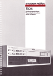
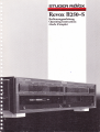
Revox 8250-5
Bedienungsanleitung
Operating Instructions
Mbde d'emploi
Vorsicht:
Attention:
Warning:
Attenzione:
Precaucidn:
Das Gerät ist in ausgeschaltetem Zustand (STANDBY) nicht von der Stromzuführung getrennt.
Cet appareil n'est pas s6par6 du r6seau lorsqu'il est d6clench6
(STANDBY)
This unit is not separated from the mains supplywhen switched off (STANDBY).
Ouesto apparecchio non ö separato dalla rete quando l'interruttore ö spento (STANDBY).
Este aparato no estä separado de la red cuando estä apagado (STANDBY).
Waarschuwing: ln uitgeschakelde toestand (STANDBY) is het apparaat niet gescheiden van de netspanning
Advarsel:
Huomio:
Forsiktig:
Varning:
Apparaten er ogsaa hvis lukket (STANDBY) under strom.
Huolimatta siitä, että virta on katkaistu laitteesta (STANDBY), sitä ei ole eristetty sähköstä.
Selvom strtmmen ikke er pa i apparatet (STANDBY), sa er det ikke skilt fra strom,
Oaktat om strömmen är avbruten iapparaten (STANDBY). sa är den ända kopplad med ström.
_
Bed ienungsanleitung
REVOX 8250
WICHTIGE
I(APITEL
HINWEISE
1
KAPEEL 2
18250-5 ' Verstärker
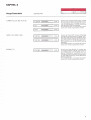
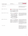
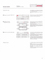
Zum besseren Verständnis ist diese Bedienungsanleitung in die
folgenden fünf Kapitel unterteilt:
tnbetriebnahme
Beinhaltet die grundlegendsten lnformationen für die lnstallation
und lnbetriebnahme des Verstärkers.
Haupt-Tastenfeld
Beinhaltet Erklärungen zu sämtlichen Hauptfunktionen des Verstärkers.
I(APITEL 3
Neben-Tastenfeld (unter der Abdeckklappe)
Beinhaltet Erklärungen zu allen Hilfs- und Sonderfunktionen, die in
Kapitel 2 nicht beschrieben sind, wie zum Beispiel SPEAKERS
A/8, PRE-OUT und MAX VOLUME.
I(APITEL 4
Technischer Anhang
Beinhaltet Wissenswertes über den Betrieb des Verstärkers, Fehlermeldungen und deren Behebung sowie die technischen Daten
und Abmessungen,
KAPITEL
5
Liste der Tastenfunktionen
ienungsanleitung fü r versierte und professionelle Anwender und gibt einen schnellen Uberblick über alle
Tastenf unktionen.
Bei nha ltet ei ne Kurzbed
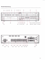
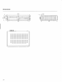
Übersichtszeichnung
Am Ende dieses Buches finden Sie eine ausklappbare Seite mit
einer indexierten Gerätezeichnung. Die im Textverwendeten lndizes in eckigen Klammern stimmen mit denjenigen auf der Zeichnung überein.
Subject to change.
Printed in Switzerland by WILLI STUDER AG
Order number 10.30 1230 (Ed 1188)
Copyright by WILLI STUDER AG
CH-8105 Regensdorf-Zurich
REVOX is a registered trade mark of
WILLI STUDER AG Regensdorf.
Schützen Sie lhr Gerät vor übermässiger Hitze und Feuchtigkeit.
Stellen Sie es so auf, dass die Lüftungsschlitze nichtverdecktwerden.
GARANTIE
Den Geräten, welche in der Bundesrepublik Deutschland verkauft
werden, liegt eine spezielle Garantieanforderungskarte bei. Entweder befindet sich die Karte in derVerpackung oder in einer Plastiktasche an derVerpackungsaussenseite. Sollte diese Karte fehlen, wenden Sie sich an lhr REVOX-Fachgeschäft oder an lhre
EVOX- La n d esve rtretu n g
Für in der Schweiz und Osterreich gekaufte Geräte gibt der Fachhändler die Garantiebescheinigung ab,
R
Bitte beachten Sie, dass die Garantie nur im Verkaufsland gültig
ist. Ausserdem machen wir Sie darauf aufmerksam, dass die Garantie erlischt. wenn am Gerät unsachgemässe Eingriffe oder
nicht fachmännische Reparaturen vorgenommen worden sind.
VERPACKUNG
Bewahren Sie die Originalverpackung auf. Bei einem Transport ist
diese Spezialverpackung der beste Schutz für lhr wertvolles Gerät.
lnhaltsverzeichnis
KAPFEL
Seite
1
lnstallation
lnbetriebnahme
Aufstellen
S icherheitsbestimmungen
4
4
4
Netzspannung
5
Packungsinhalt
Ä
Signalquellen anschliessen
Ausgänge a nschliessen
6
7
Einschalten
I(APITEL 2
Haupt-Tastenfeld
U
Signalquellen
10
Lautstärke
KAPffEL 3
Neben-Tastenfeld
Abdeckklappe
Signal-Ausgänge
Stereo-Balance
1
1
Klangsteller
Aufnahmen
Tonabnehmer-System (MM, MC)
Vor-/Endverstä rker trennen
2
2
J
4
5
Einstellungen:
- MAX VOLUME
- PWR-ON VOLUME
- SENSITIVITY: SPEAKERS,
- SENSITIVITY: INPUT
o
7
PRE-OUT
B
q
KAPFEL 4
Fehlermeldungen
OVERLOADED I I
BREAKDOWN I!I
I
21
21
21
Fehlerquellen
Mögliche Fehler und deren Behebung
22
Technischer Anhang
lR-Fernbed ienung REVOX B2OB
Netzspannung
Netzsicherung
Technische Daten
Abmessungen
24
26
26
27
zö
Kurzbeschreibung aller Funktionen
ndexierte Gerätezeichnung
Aud io-B lockscha ltbild
29
32
33
KAPFEL 5
Liste der Tastenfu nktionen
I
KAPFEL
1
T-rrTT-r-m [---r----l
.IIEE
-tt---
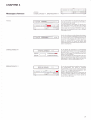
lnstallation
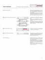
Packungsinhalt
E
;hl
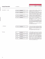
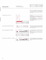
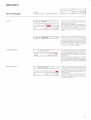
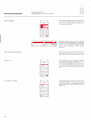
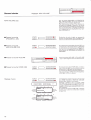
Packungsinhalt, Aufstellen
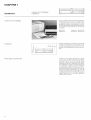
Nebst dieser Bedienungsanleitung, einem Gesamtschaltbild und dem Gerät
enthält die Pak-
kung auch ein der Landesnorm entsprechen
des Netzkabel. Bei Unstimmigkeiten wenden
Sie sich bitte an lhren Fachhändler
Die vorliegende Bedienungsanleitung ist auch
in den folgenden Sprachen erhältlich:
ENGLISH:
FRANCAIS:
Order No.: 10.30.0720
No. comm.: 10.30 0730
Aufstellen
Stellen Sie das Gerät so auf. dass die Lüftungsschlitze nicht verdeckt werden und dass
zu anderen Geräten, Mauern und Möbeln ein
Lüftungsabstand von mindestens 10 mm eingehalten wird.
Sicherheitsbestimm ungen
Schliessen Sie das Gerät nur mit dem beigepackten Netzkabel am Stromnetz an.
Halten Sie das Gerät stets trocken und ver
wenden Sie es nie in Nassräumen (Badezimmer Waschküche, Keller, etc.).
Das Gerät ist im ausgeschalteten Zustand
(Standby) nichtvon der Stromzufuhr getrennt.
Teile im Gerät führen immer Netzspannung!
Das Gerät ist für den Betrieb in Normallage
(waagerecht liegend) konzipiert.
Bei Fehlfunktion oder Defekt ist sofort der
Netzstecker zu ziehen und das Gerät einem
REVOX-Fachhändler zur Kontrolle zu übergeben.
L____l-EE--El
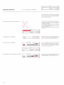
lnbetriebnahme
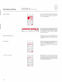
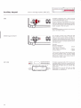
N
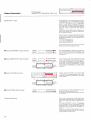
etzspannungs-Kontrol le
I
lLl
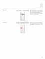
Netzspannung,
Signalquelle anschliessen
e
----
"8^8u
:
({E)
888@888888Q
o
.
t@CIo@lm
@
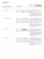
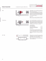
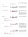
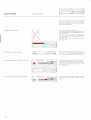
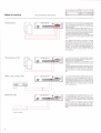
Signalquellen anschliessen
-.
o
Bo
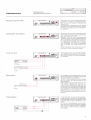
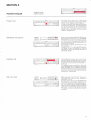
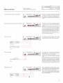
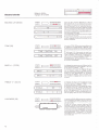
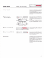
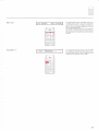
Uberprüfen Sie. ob der aufgedruckte Spannungswert unterhalb des Netzanschlusses
[56] mit der vorhandenen Netzspannung
übereinstimmt.
Das Gerät kann nötigenfalls auf eine andere
Netzspannung umgeschaltet werden. Lassen
Sie diese Umschaltung von lhrem Fachhändler ausführen.
Vergewissern Sie sich, dass alle Zusatzgeräte
lhrer Anlage zumindest ausgeschaltet. besser
aber vom Netz getrennt sind.
Verbinden Sie nun die Audio-Ausgänge
(OUTPUT) dieser Geräte (Signalquellen) wie
Tuner. CD-Spieler und Tape Deck mit den da
für vorgesehenen Eingängen des Verstärkers.
Am Hilfseingang AUX [43] kann ein zusätzlicher CD-Spieler, ein drittes Tonbandgerät
oder ein zweiter Tuner angeschlossen wer
den.
Achten Sie darauf, dass die Kanäle links
und rechts (R) nicht vertauscht werden.
o
Tuner CD,
----
@
^+
o
rFl
tU
o
(L)
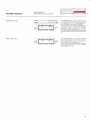
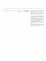
Die Ausgänge eines Tuners (Radio Empfängers) oder CD-Spielers sind mit den Eingängen TUNER [46] oder CD l42l des Verstärkers
zu verbinden.
Tuner
o
Plattenspieler
:-::-
@
^+
@
Eo
Die Ausgänge eines Plattenspielers sind mit
den entsprechenden Eingängen PHONO [38/
401 des Verstärkers zu verbinden.
VerfLigt lhr Plattenspieler über eine Erdungslitze, so ist diese am Masse-Anschluss [39]
anzusch iessen.
Plattenspieler mit einem herkömmlichen "moI
ving magnet" Abtastsystem sind am
An-
schluss mit der Bezeichnung MM [40] und
solche mit einem "moving coil" Abtastsystem
am Anschluss mit der Bezeichnung N/C [38]
anzuschliessen. Für einen Betrieb mit MC-Abtastsystemen muss der Verstärker mit dem
MC-Vorverstärker nachgerüstet worden sein
(Option).
Phono
Tonbandgeräte
o
E-:-
@
-+
o
Eo
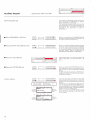
An den Verstärker können zwei Tonbandgeräte angeschlossen werden. Die Ausgänge der
Tonbandgeräte sind mit den Eingängen TAPE
'1
bi
[45] und TAPE 2 [44] des Verstärkers zu vernden.
Um mit den Tonbandgeräten auch Aufnah
men machen zu können. sind deren Eingänge
noch mit den entsprechenden Ausgängen
TAPE 1 [50] und TAPE 2 [49] des Verstärkers
zu verbinden.
Tape
1
5
r-rn-|-_r-m
lnbetriebnahme
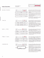
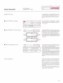
Lautsprecher
r---r--r fl
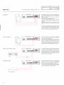
Ausgänge anschliessen
@ '.'i
o
1r-l
Uo
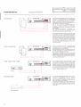
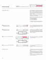
Zwei Lautsprecherpaare können an den vergoldeten Lautsprecherklemmen SPEAKERS
A [54] und SPEAKERS B [55] des REVOX
8250 ' Verstärkers angeschlossen werden.
Lautsprecherboxen mit einer lmpedanz von 4
oder BOhm sind zu bevorzugen.
Nur in der Farbe korrespondierende Anschlüsse zwischen Verstärker und Lautsprecherboxen miteinander verbinden (korrekte
Phasenlage).
Die
Masse-Verbindungen (schwarze An-
schlüsse) der einzelnen Lautsprecher dÜrfen
nicht miteinander verbunden werden.
Um Leistungsverluste der Lautsprecher möglichst klein zu halten. verwenden Sie die den
Lautsprecherboxen beigepackten Spezialkabel oder solche mit einem möglichst grossen
Ouerschnitt. Kabel bis zu einem Durchmesser
von 4mm \--12mm2) können an den Klemmen bequem angeschlossen werden. Handelsübliche Bananenstecker (Q 4mm) sind direkt einsteckbar.
Aktive Lautsprecherboxen (mit eingebautem
Verstärker) sind am Ausgang PRE-AMP [53]
Aktrv-Lautsprecher
des Verstärkers anzuschliessen.
Dieser Ausgang wird durch Druck auf die Taste PRE-OUT [34] im zweiten Tastenfeld (un-
ter der Abdeckklappe) aktiviert.
Bei aktiven Lautsprechern ist die maximale
Kabellänge nur auf die in der entsprechenden
Bedienungsanleitung empfohlenen Werte limitiert. solange gut abgeschirmte Audio-Kabel verwendet werden.
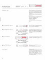
TAPE 1 [50], TAPE
2149)
o
tm
ILJJ
o
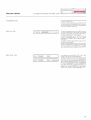
Die Ausgänge TAPE 1 [50] und TAPE 2 [49]
sind für die Aufnahmezweige derTonbandgeräte TAPE 'l und TAPE 2 reserviert. BeiWiedergabe ab einem derTonbandgeräte ist derAufnahme-Ausgang.für dieses Gerät abgeschal-
tet, damit eine Uberspielung (TAPE COPY)
ohne Rückkoppelung von einem Tonbandgerät zum andern möglich ist.
Am Ausgang N/ONITOR [48] können ein zusätzliches Tonbandgerät oder ein weiterer
Verstärker angeschlossen werden, die von
der Lautstärke-. Klangsteller- und Balance-
MONITOR
Stellung unbeeinflusst bleiben.
Uber diesen Ausgang ist immer diejenige Signalquelle hörbar, die auch über die Verstärker-Ausgänge (SPEAKERS A/8, PRE-AMP) zu
hören ist.
Power Amplifier
T-rnT-r-m [---r--_-l
lnbetriebnahme
E
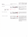
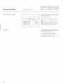
Ausgänge anschliessen,
Einschalten
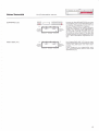
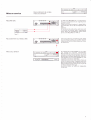
Am Ausgang RECORD [51] kann zum Beispiel
der Aufnahmezweig eines zusätzlichen Tonbandgerätes angeschlossen werden.
RECORD [51]
Dieser Ausgang führt immer das mit RECOUT [19] gewählte oderdas REC:lN [23] Auf-
nahmesignal.
Vorsicht:
Bei derVerwendung dieses Ausganges ist darauf zu achten. dass keine Audio-Schleife
(Rückkopplung) entsteht (TAPE 1 abspielen
und gleichzeitig über den Ausgang RECORD
auf TAPE 1 aufnehmen.
Tape 3
Netz anschliessen
o:
@
o
t(
o
Do
Wenn alle Audio-Verbindungen gemacht sind
(Signalquellen und Lautsprecher angeschlossen), darf der Verstärker mit dem beigepackten Netzkabel ans Netz angeschlossen werden.
t
Gerät einschalten
r--T-l_rr-r-m
-IIEE
.ll---
[---l----l I
Drücken der Taste POWER Ul auf der Geräte-
front schaltet den REVOX 8250 ' Verstärker
ein. die beim letzten Ausschalten aktivierte Si-
gnalquelle wird wieder gewählt. Nochmaliges Drücken der Taste POWER [1] schaltet
den Verstärker wieder aus (Standby).
Das ausgeschaltete, aber mit dem Netz verbundene Gerät befindet sich im Standby-Mo-
dus(: 3"t"',."haft). Dadurch
kann das Gerät
auch mit der Infrarot-Fernbedienung bequem
vom Hörplatz aus ein- und ausgeschaltetwerden.
Der Stromverbrauch in Standby ist vernachlässigbar gering (ca.'l 0 Watt).
KAPITEL 2
Haupt-Tastenfeld
TUNER
1121,
Signalquellen
Drücken der entsprechenden Taste schaltet
CD t8l, AUX tel
den jeweiligen Eingang zum Verstärker durch.
Die Signalquelle wird im Display [']51 zusam-
men mit der aktuellen VOLUME-Einstellung
und BALANCE-Stellung angezeigt.
Der Verstärker kann mit Auswahl der Signalquelle auch direkt eingeschaltet werden.
TAPE 1 [11]. TAPE
2
[10]
i i ii:::!i:: r:
i i ia 1- .a
.!ii i
::!.
Drücken derTasteTAPE'1 ['11] oderTAPE 2 [10]
schaltet den entsprechenden Eingang TAPE 1
[45] oder TAPE 2 l44l zum Verstärker durch.
Die eingeschaltete Signalquelle wird im Display [15] zusammen mit der aktuellen VOLUME-Einstellung und der BALANCE-Stellung
angezeigt.
Der Verstärker kann mit Auswahl der Signal
quelle auch direkt eingeschaltet werden.
PHONO l7l
Drücken der Taste PHONO l7l schaltet den
am Eingang PHONO l3?l40) angeschlossenen Plattenspieler zum Verstärker durch. lm
Display ['15] wird die Signalquelle mit dem
Schriftzug PHONO zusammen mit der aktuellen VOLUME-Einstellung und der BALANCEStellung angezeigt.
Der Verstärker kann mit Auswahl der Signalquelle auch direkt eingeschaltet werden.
Haupt-Tastenfeld
voLUME
+l-
- 20 dB [5]
Hinweis
l2l3l
==
Lautstärke
f
] ::=-::
Drücken der Taste VOLUME + [2] erhöht die
Lautstärke, Drücken derTaste VOLUME - [3]
hingegen senkt die Lautstärke ab.
Die Einstellung kann mit zwei Geschwindigkeiten vorgenommen werden. Drücken der
Tasten unterhalb der Markierungen ( und )
verändert die Lautstärke langsam in kleinen
Schritten ('1 dB). Drücken unterhalb der Markierungen ( und )verändert die Lautstärke rasch in grösseren Schritten (3 dB).
lm Display [15] wird anstelle der BALANCEStellung das Symbol der betätigten VOLUMETaste ((. ) oder <<, >>) angezeigt.
Während der Einschaltphase des Verstärkers
kann das Volumen verringert, nicht aber erhöht werden.
Die maximal erreichbare Lautstärke richtet
sich nach dem für die eingeschaltete Lautsprechergruppe eingestellten MAX VOLUME.
Sind beide Lautsprechergruppen eingeschaltet, so ist die kleinere maximale Lautstärke
massgebend.
Der Verstärker kann mit den VOLUME{asten
auch eingeschaltet werden.
rücken d ieser Taste verringert d ie Lautstärke
auf einmal um 20d8. Nochmaliges Drücken
verringert die Lautstärke wiederum um 20 dB
und so fort. bis das Lautstärke-Minimum erreicht ist.
Durch Drücken derTasteVOLUME + [2] kann
die Lautstärke wieder erhöht werden.
D
lhr REVOX
8250' Verstärker ist für zukünftige
Anwendungen bereits gerüstet. Zusammen
mit dem REVOX 8200 ' Controller, der unter
den Verstärker montiertwird, kann mitderTaste VIDEO [6] auf die Zweitfunktionen TV,
VCR 1, VCR 2 und DISC zugegriffen werden.
Damit ist es möglich, die Audio-Signale eines
Fernsehers (TV), zweier Videorecorder
(VCR1, VCR2) und eines Bildplattenspielers
(DISC) mit der HiFi-Anlage zu verbinden. Zu-
sätzlich können die Video-Signale der vier
Ouellen mit dem Controller analog zur Schal-
tung der Audio-Signale zu einem Monitor
(Fernsehed geschaltet werden.
10
KAPITEL 3
r-T-fff-r-fn
Neben{astenfeld
Abdeckklappe
S ignal-Ausgä nge,
SPEAKERS AIB
oc
Abdeckklappe
f-ilTr-r-fn [---r--l E
:
l35l37l
t---r--__..l fl
:l==. r::==::
EEE EOTI
ECf r--r----1 EO
-EE
f-rn-rT-m r--T----l tI
Die Rauchglas Abdeckung des zweiten Tastenfeldes wird durch Druck auf die Taste
OPEN [4] geöffnet, das LC-Display 124)wird
beleuchtet.
Zum Schliessen wird die Klappe einfach wie
der bis zum Einrasten hochqeschoben. Dabei
erlischt die Beleuchtung des Display und jeder im zweiten Tastenfeld vorgenommene
aber noch nicht beendete Programmier-Vorgang wird abgebrochen und der vorherige
Zustand wieder hergestellt.
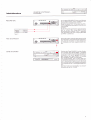
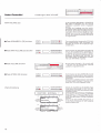
Drücken der Taste SPEAKERS A [35] schaltet
die Lautsprechergruppe A ein und aus, Drükken derTaste SPEAKERS B [37] die Lautsprechergruppe B. Um beim Schalten störende
Geräusche zu vermeiden. blendet der Mikro
prozessor die Lautstärke schnell aus und wieder ein.
Beide Lautsprechergruppen können gleichzeitig ein- oder auch ausgeschaltet sein (PHONES)
Rechts. neben dem Display[15] signalisierteine gelbe LED 117l die eingeschaltete Laut
sprechergruppe SPEAKERS A [54] und eine
LED [16] die eingeschaltete Lautsprecher-
gruppe SPEAKERS B 1551.
PHONES [18]
f-T_Tl-f-r-fn
I
fl
Kopfhörer-Betrieb ist immer möglich. Dazu isl
lediglich ein Kopfhörer in die dafürvorgesehene Buchse an der Gerätefront einzustecken.
Die Lautstärke ist mlt den Tasten VOLUME
[2/3] einstellbar.
+/
lst keine Lautsprechergruppe eingeschaltet,
so ist das für PHONES gesetzte l\1AX VOLUME
für die maximaleinstellbare Lautstärke massgebend. Andernfalls ist das für die eingeschal
tete Lautsprechergruppe oder, wenn beide
Lautsprechergruppen eingeschaltet sind, das
tiefere MAX VOLUMF gültig
PRE-OUT [34]
-EE
r-TT-|-r-r-fn
EOOFEEC]
DEf---r-lE
---r----l E
Durch Drücken der Taste PRE-OUT l34l wird
der Vorverstärker Ausgang PRE-AMP [53]
des Verstärkers ein- und ausgeschaltet.
Wie bei den Lautsprecher-Ausgängen SPEAKERS A/B t54l551 blendet der Mikroprozessor die Lautstärke beim Umschalten schnell
aus und ein.
Dieser Ausgang kann unabhängig von den
beiden Lautsprechergruppen A und B geschaltet weden.
Links. neben dem Display [15] signalisierteine
grüne LED [13] den eingeschalteten Vorver
stärkerAusgang.
11
f-TTfT-T--fn
Neben-Tastenfeld
Stereo-Balance,
Klangsteller
Mit den beiden Tasten BALANCE L [30] und
tt
BALANCE LIR l30l32l
E
---T-----l
BALANCE R [32] lässt sich das stereophone
Klangbild zugunsten des einen oder anderen
Kanals an eine asymmetrische Hörposition
anpassen.
!............................................i1..................................::::......i:::'
Beide Kanäle können in + 9 dB Stufen verändert werden. Beim Drücken einer der Tasten
zeigt ein Leuchtbalken im Display [15] die ak
tuelle BALANCE Einstellung für ein paar Sekunden automatisch an.
Der Balance Ausgleich lässt sich wie folgt
wieder einstellen:
Die Taste des abgeschwächten
Kanals
dauernd drücken. die Einstellung stoppt automatisch in Balance-M ittenstellung.
TONE [29]
-DEIDOO
E-r--r r--rcf -
E T]E
Die Taste TONE [29] schaltet den Klangsteller
(BASS, TREBLE) ein und aus. Damit ist ein
Vergleich zwischen linearem (unbeeinflusstem) Frequenzgang und einer vorgenomme
nen Klangkorrektur möglich.
lm Display [15] wird für ein paarSekunden der
aktuelle Status dieser Funktion angezeigt.
TONE CONTROL ON/OFF und im LC-Display
[24] erscheinen bei TONE CONTROL ON die
Balkensymbole für BASS und TREBLE.
Das Einschalten dieser Funktion hebt die
Funktion LOUDNESS auf.
BASS
IIE-DE-Df----'l l----r-E
+/- l27l25l
-EE
TREBLE
+l-
l33l31l
tt
EDEI
i lr
l'
--)f----rf----r-cf
l';i
Mit dem Bass Steller können tiefe Frequenzen
in 4 Stufen angehoben (BASS + [27]) oderabgesenkt (BASS - [25]) werden.
Beim Drücken einer Taste des Bass-Stellers
wird die aktuelle Einstellung im Display [15]
für ein paar Sekunden angezeigt. und im LCDisplay [24] erscheinen die Balkensymbole
fur BASS und TREBLE. Jeder weitere Tastendruck verändert die Einstellung in der entsprechenden Richtung.
Mit dem Treble Steller können hohe Frequen
zen in 4 Stufen angehoben (TREBLE + [33])
oder abgesenkt (TREBLE - [31]) werden.
Beim Drücken einer Taste des Treble Stellers
wird die aktuelle Einstellung im Display ['15]
für ein paar Sekunden angezeigt, und im LCDisplay [24] erscheinen die Balkensymbole
fur BASS und TREBLE Jeder weitere Tastend ruck verändert d ie E nstel lu ng n der entsprechenden Richtung.
i
LOUDNESS [28]
E)
EEE-T]FO
o!r----r--cf
Die Taste LOUDN l28l schaltet die lautstär
keabhängige Klangregelung, welche der natürlichen Charakteristik des Gehörs angepassl
ist. ein resp. aus.
odB
Ausgehend von der mit MAX VOLUME gepRE our
setzten maximalen Lautstärke bewirkt sie eine
SeEAKERS Anhebung der tiefen Frequenzen bei abge
EE
vol
PHONES
SPEAKERS
PWR ON
i
-1m
NPUI
LOUDNESS
PHONO
MC
PROGRAM
SEPARATED
senkter Lautstärke (1 Korrekturschritt pro
10 dB VOLUIV E-Absenkung).
Beim Aktivieren der LOUDNESS-Funktion
wird der manuell einstellbare
Klangsteller
(BASS. TREBLE) automatisch ausgeschaltet.
Andererselts hebt Drücken der Taste TONE
[29] die LOUDNESS-Funktion auf
12
r-TTff-r-fn
Neben-Tastenfeld
Aufnahmen
---r--__l fl
Aufnahmen (REC:lN, REC-OUT)
Aufnahmen können auf zwei verschiedene
Arten gemacht werden.
Entweder kann die gehörte Signalquelle zugleich auch Aufnahmequelle sein, oder die
gehörte Signalquelle und die Aufnahmequelle
können sich voneinander unterscheiden.
REC:IN [23]
Diese Aufnahmeart ist bei Auslieferung des
Verstärkers eingestellt. Das Display [15] zeigt
das bis anhin beschriebene Bild mit angewählter Signalquelle. Volumen-Stellung und
Ba lance-Einstellung.
Dabei ist die gehörte Signalquelle gleichzeitig
auch die bei den Ausgängen RECORD [15],
[50] und TAPE 2 [49] ausgegebene
TAPE 1
Aufnahmequelle.
Hinweis:
Die Ausgänge TAPE 1 [45] undTAPE 2l44l
sind gegenseitig verriegelt.
lst beispielsweise TAPE '1 Signalquelle, so ist
der eigene Aufnahme-Ausgang TAPE 1 [50]
gesperrt, um eine Rückkopplung zu vermeiden. Mit TAPE 2 kann jedoch das Signal aufgenommen werden.
REC-OUT [19]
Drücken der Taste REC-OUT 119l verändert
sofort die Anzeige im Display ['15].
Nach dem Wort lN: steht die gerade gehörte
Signalquelle (2. B.: TUNER). Für den Aufnahmezweig kann nun hinter REC: eine Signalquelle angewähltwerden (2. B.: PHONO). Dies
hat zur Folge, dass über die Ausgänge SPEAKERS A [54], SPEAKERS B t55], PRE_AMP
[53] und MONITOR [48] die
Signalquelle
TUNER gehört und über die Ausgänge TAPE 1
[50],TAPE 2 [49] und RECORD [51] die Signalquelle PHONO aufgezeichnet werden kann.
13
[-ffff-r-fn [---r--__l f]
Neben-Tastenfeld
Tonabnehmer-System (MM, MC)
Plattenspieler mit einem MM (moving ma-
N/ N/
gnet) Abtastsystem sind am Eingang PHONO
Ni N/ [40] anzuschliessen.
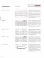
Für eine optimale Wiedergabe der Schallplatten ist die korrekte Anpassung des PHONOEinganges von g rund legender Bedeutu ng, d ie
Eingangs Kapazitätmussmitdem SchalterPF
[41] auf der Geräte-Rückseite dem Abtastsystem angepasst werden.
Ausnahme:
Beim Anschluss eines Plattenspielers REVOX
8291 ist immer die Stellung 150 pF zu wählen.
Für die Abtastsysteme Elac EMM 150 und
Shure V15V sind 150 pF einzustellen. Der Ein
stellwert f ür andere Systeme ist entsprechend
dem folgenden Beispiel errechenbar. Die Ka-
Einstellung:
pazitäts-Werte müssen den technischen Da-
tenblättern der Hersteller von Plattenspieler
und Abtastsystem entnommen werden.
Einstell-Beispiel:
om ina l-Kapazität
des Tonabnehmers:
N
375 pF
Kapazität des PlattenspielerAusganges (Kabelkapazität)
Einstellwert:
:
-225pF
150pF
Kann der Wert nicht exakt eingestellt werden,
so ist der nächstmögliche Wert einzustellen.
Ein kleinerer Einstellwert bewirkt eine Anhebung der (extremen) Höhen, ein grösserer
Wert bewirkt Verluste im (extremen) Höhenbereich
MC l20l
tt
IEvoL
-r0o
! I I r ls! r l;
PHONES
SPEAKERS
PWR ON
- äts$ +
V
PHONO
14
Plattenspieler mit einem MC (moving coil)Abtastsystem sind am Eingang PHONO MC [38]
-Er----rr--EE
anschliessbat wenn der Verstärker mit der
o dB
Option MC-Vorverstärker bestückt ist.
Durch Drücken der Taste N/C t20l wird der
1 ! r !&!! r ! |
- ffinlllf I pREour MC-Vorverstärker ein und der MM-Vorver
SPEAKERS stärkerauSgeschaltet.
11
INPUT
MC
PROGRAM
SEPARATED
-[rrr-r-m r---r---r E
NebenTastenfeld
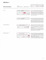
SEPARATED [21]
Vor-/Endverstä rker trennen
EEEEEEE
ECf r-1 r-EI
EID
voL
PHONES
-10o
dB
75
rrrilENli,
tliltsiltr
- BASS + - TRSSLE +
SPEAKERS
V
PWR ON
PHONO
MC
PRE.OUT
SPEAKERS
INPUT
PROGRAM SEPARATED
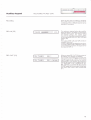
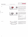
D rücken derTaste SEPARATED [21] trennt den
Vorverstärker intern vom Endverstärker ab. lm
LC-Display l24l wnd dies mit dem Pfeil auf
den Schriftzug SEPARATED angezeigt.
Mit dieser Funktion ist es möglich. beispielsweise einen Equalizer in den Signalweg zu
schalten. Am Ausgang PRE-AMP [53] (mit
der Taste PRE-OUT [34] schaltbar) kann das
Vorverstärker-Signal abgenommen, über den
Equalizer geführt und am Eingang PWR-AMP
l47l in den Endverstärker eingespiesen wer-
den.
PWR-AMP [47]
voL
PHONES
SPEAKERS
PWR ON
-100
tlllt8tttl
* ts&SS *
ltNttxtill
* TR€BLE +
V
PHONO
MC
PROGRAM SEPARATED
PRE-OUT
SPEAKERS
INPUT
Der Eingang PWR-AMP [47] führt ein angelegtes Signal direktzum Endverstärker und ist
mit den VOLUME-Tasten nicht mehr beeinf
lussbar.
Dieser Eingang ist nur eingeschaltet, wenn
Vor- und Endverstärker getrennt sind (Taste
SEPARATED [21]).
15
r-[rr-r-m r---l----l E
Neben-Tastenfeld
Einstellungen: MAX VOLU
ME
Für die Ausgänge SPEAKERS A, SPEAKERS B,
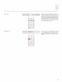
MAX VOLU\AE 122]
PRE-AMP und PHONES kann die maximal
einstellbare Lautstärke einzeln eingegeben
werden.
Für jeden der Ausgänge muss der nachfolgend beschriebene Einstellvorgang durchlaufen werden. Die anderen Ausgänge sind auszuschalten. Wenn mehrere Ausgänge eingeschaltet sind, wird die Einstellung automatisch für die Lautsprechergruppe SPEAKERS
A vorgenommen.
o
Taste SPEAKERS
A i35l
drücken E-
EEEEEIC]
EE r--1 r---1 EE
-u-
O Taste MAX VOLUMEI22I drücken
cfElEEECSCf
EEI
EEr---1
r--1
EE
Den einzustellenden Ausgang durch Drücken
der entsprechenden Taste einschalten (für
PHONES [']Bl müssen alle Ausgänge ausgeschaltet sein).
Durch Drücken der Taste MAX VOLUME [22]
wird in den Eingabe-Modus geschaltet. lm
LC-Display 12fl wnd dies mit einem Balkensymbol für die aktuelle Einstellung und dem
blinkenden Schriftzug MAX VOLUME und
den beiden Pfeilen auf PROGRAIV und PHONES oder SPEAKERS angezeigt.
O Taste VOLUME drücken
o
Taste sToRE [36] drücken
Werks-Einstellung
Mit den Tasten VOLUME + [2] und VOLUIVE
- [3] kann nun die gewünschte maximale
Lautstärke eingestellt werden.
ft======IE
trlc-
r----lc=
EE!
VOL
1M
VOL
Durch Drücken derTaste STORE [36] wird die
eingestellte Lautstärke als für diese Lautsprechergruppe maximal zulässige Lautstärke abgespeichert.
Eine höhere Lautstärke lässt sich erst wieder
einstellen, wenn mit obigem Vorgang ein höheres MAX VOLUIVE eingestellt wurde.
T]EEC]EEE
EEr-1 r-1 Dl
Die bei der Auslieferung des Gerätes eingestellte Werks-Einstellung für MAX VOLUME
und PWR ON-VOLUIVE kann jederzeitwieder
dB
-75
llllll]]Ir I I ]] | l
PHONES
SPEAKERS
PWR ON
EEEEEEE
EEE-EI
tIII|!
I
PRE-OUT
< MAX VOLUME
SPEAKERS
INPUT
Y
PHONO
MC
1m
-75
PROGRAM SEPARATED
-50
-25
0
dB
l]tlrlll! I r Lr r r I I I I I I I I r
PHONES
SPEAKERS
PWR ON
PRE OUT
< MAX VOLUME
V
PHONO
16
MC
NOMINAL
PROGRAM SEPARATED
SPEAKERS
INPUT
eingestellt werden:
Die Taste MAX VOLUME [22] so oft betätigen,
bis im Display [15] der Schriftzug RESTORE
NOMINAL? und im LC-DisplaV 124) der blinkende Schriftzug MAX VOLUME NOIVINAL
erscheint.
Wird nun die Taste STORE [36] gedrückt, so
ist die Werks-Einstellung für alle Ausgänge
wieder programmiert.
Tt-t-tT-r-fn [---r--_-l
Neben-Tastenfeld
Einstellungen: PWR-ON VOLUME
t]
o
Mit PWR ON-VOLUIVE (POWER ON_VOLUME) wird die Lautstärke bezeichnet, mit der
das Gerät eingeschaltet wird, egal mit wel-
PWR-ON VOLUME
cher VOLUME-Einstellung das Gerät ausgeschaltet wurde.
Auch diese Einstellung kann den persönlichen
Bedürf nissen angepasst werden. Es empf iehlt
sich aber diese Einstellung nicht zu hoch zu
wählen (Einschalten zu nächtlicher Stunde).
O Taste MAXVOLUMEI22I drücken
E-DEEEE
EEf---r r----rEf E
E E}I
VOL
dB
-75
-100
llllllllllt I I ilt | | | I I t, I t I I
PHONES
SPEAKERS
PWR ON
PRE OUT
<
&?lAX
VOIUMT
Y
PROGRAM SEPARATED
PHONO MC
vol
100
PHONES
SPEAKERS
PWR ON
o
Taste sToRE f36l drücken
Werks-Einstellung
r||r
rr,, i r I I I I I
0
dB
r
PRE OUT
{
MAX VüIIJME
PHONO
O Taste VOLUME drücken
-25
-s
-75
irlll|]ti
SPEAKERS
INPUT
!\'OMNI\I/\L
Y $t0M|l{;ll
MC
SPEAKERS
INPUT
PROGRAM SEPARATED
[Tfl-l--r-fn-n
DOEEEEO
C]DE
Die Taste MAX VOLUME [22] so oft drücken,
bis der Pfeil im LC-Display l24l auI PWR ON
zeigt.
Damitwird in den Eingabe-Modus für die Einschalt-Lautstärke (PWR ON-VOLUME) geschaltet.
lm LC-Display 124 wnd dies mit einem Balkensymbol für die aktuelle Einstellung und
dem blinkenden Schriftzug IVAX VOLUIVE
und den beiden Pfeilen auf PROGRAM und
PWR ON angezeigt.
oEf----1 f----1DI
Mit den Tasten VOLUME + [2] und VOLUN/E
- [3] kann nun die gewünschte EinschaltLautstärke eingestellt werden.
Durch Drücken derTaste STORE [36] wird die
ei ngestel lte La utstärke a ls Ei nscha lt-Lautstä rke (PWR ON-VOLUIV E) abgespeichert.
Eine andere Einschalt-Lautstärke lässt sich jederzeit neu programmieren.
Die bei der Auslieferung des Gerätes eingestellte Werks-Einstellung für MAX VOLUIVE
und PWR ON-VOLUME kann jederzeit wieder eingestellt werden:
Die Taste MAX VOLUME l22l so oft betätigen,
bis im Display ['15] der Schriftzug RESTORE
NOMINAL? und im LC-Display 124) der blinkende Schriftzug MAX VOLUN/E NOMINAL
erscheint.
Wird nun die Taste STORE [36] gedrückt. so
ist die Werks-Einstellung für alle Ausgänge
wieder programmiert.
17
f-rn-f-T--[n t---r----l
Neben-Tastenfeld
f_]
Einstellungen:
SENSITIVITY: SPEAKERS, PRE_OUT
Mit SENSITIVITY (Empfindlichkeit) kann der
sENSrrvrTY t26l
Ausgangspegel des Vorverstärker-Ausgan-
ges PRE-AMP gegenüber dem Ausgangspe-
gel der Lautsprecher-Ausgänge SPEAKERS
A/B verändert und der nominale Ausgangspegel der einen Lautsprechergruppe gegenüber der anderen angehoben oder gesenkt
werden.
Weiter kann die Verstärkung der Eingangsverstärker den Pegeln der einzelnen Signalquellen angepasst werden.
Wenn mehrere Ausgänge gleichzeitig eingeschaltet sind, so wird der nominale Ausgangspegel des Ausganges mit der höchsten Priori-
tät aktiviert:
'1
. Priorität: SPEAKERS A
2. Priorität: SPEAKERS B
Keine Priorität: PRE-OUT
Die Einstellung erfolgt schrittweise, für jeden
Eingang und jeden Ausgang einzeln.
O Taste SPEAKERS
A t35l drücken
O Taste SENSITIVITY 126l drücken
EEE
EEEC]EII
ncr-1 --rlcf
-l-u
ECI]OEEE
aof----r:oE
75
VOL
PHONES
SPEAKERS
PWR ON
-o+
O Taste VOLUME drücken
Nall!
v
PHONO
MC
I
SENSITIVITY >
PRE.OUT
SPEAKERS
75
-1m
PHONES
trltf -
t lli I I I I l
odB
I
V
tt
MC
angezeigt.
Mit den Tasten voLUME + [2] und VOLUME
- [3] kann der Ausgangspegel des eingeschalteten Ausganges angehoben oder abgesenkt werden.
SENSITIVITY >
SPEAKERS
PHONO
symbol für die aktuelle Einstellung und dem
blinkenden Schriftzug SENSITIVITY und den
beiden Pfeilen auf PROGRAM und SPEAKERS
INPL JT
-25
-o+
PWR ON
Durch Drücken der Taste SENSITIVITY [26]
wird in den Eingabe-Modus geschaltet. lm
LC-Display l24l wnd dies mit einem Balken-
PROGRAM SEPARATED
I I I I I I rl M'll
Werks-Einstellung
!III||II
f-T_ffr-r-mEE
voL
O Taste STORE 136l drücken
dB
-25
I t, I I ; I : I
Den einzustellenden Ausgang durch Drücken
der entsprechenden Taste einschalten. Die
anderen Ausgänge (PRE-OUT, SPEAKERS B)
ausschalten.
PRE.OUT
SPEAKERS
INPUT
PROGRAM SEPARATED
oEr---rr--rEl
Durch Drücken derTaste STORE [36] wird der
eingestellte Pegel abgespeichert.
Ein anderer Pegel lässt sich jederzeit neu programmreren.
Die bei der Auslieferung des Gerätes eingestellte Werks-Einstellung fur die Empfindlich-
keiten kann jederzeit wieder eingestellt wer-
den:
Die Taste SENSITIVITY [26] so oft betätigen,
bis im Display [15] der Schriftzug RESTORE
NOMINAL? und im LC-Display l24l der blinkende Schriftzug SENSITIVITY NOMINAL erscheint.
Wird nun die Taste STORE [36] gedrückt. so
ist die Werks-Einstellung für alle Ein- und Ausgänge wieder programmiert.
1B
T-T-n-r-r-m [---r----l
Neben-Tastenfeld
Einstellungen:
SENSITIVITY: INPUT
E
;t"ffi
Mit SENSITIVITY (Empfindlichkeit) kann die
Verstärkung der Eingangsverstärker den Pegeln der Signalquellen angepasst werden.
Die Einstellung erfolgt für jeden Eingang ein-
SENSTTTVTTY 126l
ze ln.
O Taste TUNER [12] drücken
r-rn--r-rn r--r--__l E
Die einzustellende Signalquelle (TUNER.
rAPE 112, AUX, CD. PHONO, TV, VCR 112,
DISC) durch Drücken der entsprechenden Ta-
ste anwählen.
O Taste SENSITIVITY 126l drücken
EDI]EEEE
IEf-] r---r-E
EDE}
VOL
]M
dB
-25
75
i,i!l!ii!it!t1!!MIM
PHONES
SPEAKERS
PWR ON
Y>
PHONO MC
VOL
1m
-75
PROGRAM
0
Empfindlichkeit der Eingänge geschaltet.
lm LC-Display l24l wtrd dies mit einem Bal-
PRE OUT
kensymbol für die aktuelle Einstellung und
SPEAKERS
NPUT
dem blinkenden Schriftzug SENSITIVITY und
den beiden Pfeilen auf PROGRAN/ und INPUT
SEPARATED
-25
DieTaste SENSITIVITY [26] so oftdrücken, bis
der Pfeil im LC Display 124) auI INPUT zeigt.
Dadurch wird in den Eingabe Modus für die
a
ngezeigt.
dB
tt
PRE OUT
PHONES
SPEAKERS
PWR ON
SPEAKERS
INPUT
PHONO
O Taste STORE [36] drücken
Werks-Einstellung
EIf E
tt
MC
PBOGRAM SEPARATED
OE}EEEEE
=----E
Durch Drücken der Taste STORE [36] wird ein
automatischer Pegel-Messvorgang des entsprechenden Einganges aktiviert.
Beim Loslassen derTaste STORE [36] wird die
Verstärkung des entsprechenden Eingangver
stärkers dem gemessenen Pegel angepasst
und abgespeichert.
Während der Messung erscheint im Display
['15] nach der Signalquelle die Meldung MEA
SURING. G ibt die Signalquelle kein oder ein zu
geringes Signal ab (ausgeschaltet), so erscheint die Meldung LOW LEVEL und die Verstärkung des Eingangverstärkers bleibt unverändert.
Die bei der Auslieferung des Gerätes eingestellte Werks-Einstellung für die Empfindlich
keiten kann jederzeit wieder eingestellt werden:
Die Taste SENSITIVITY [26] mehrmals betätigen, bis im Display [15] derSchriftzug RESTO-
RE NON/INAL? und im LC-Display 124) der
blinkende Schriftzug SENSITIVITY NON/ INAL
erscheint.
Wird nun die Taste STORE [36] gedruckt. so
ist die Werks Einstellung für alle Ein- und Ausgänge wieder programmiert.
19
KAPITEL 4
Fehlermeldungen
OVERLOADED
III,
BREAKDOWN !!!
f-TlTn--Tn [--t----r E
=II"''.?r r::::l:
Bei einer übermässigen
f-T-rfrT-rn r--___-] E
Temperatur-Erhö
hung der Leistungs-Endstufen wird die Lautstärke automatisch um 10dB abgesenkt.
Dieser Vorgang wird im Display ['15] mit dem
blinkenden Symbol(( anstelle der Balance-Stellung angezeigt. Die Lautstärke kann
mit den Tasten VOLUME noch abgesenkt, vor
aber nicht
dem Erlöschen der Anzeige ((
mehr erhöht werden.
Nach dem Abkühlen der Leistungs Endstufen
erscheint im Display [15] wieder die gewohnte Anzeige von Signalquelle und Aufnahmequelle oder Sionalquelle, Volumen- und Ba
lance-Einstellung. Die Lautstärke kann nun
wieder frei erhöht werden. Jedoch sollte die
Ursache für die Fehlermeldung (unzureichende Belüftung) abgeklärt und behoben werden.
OVERLOADED
!I
Kühlen sich die Leistungs-Endstufen nach der
Fehlermeldung
nicht ab, sondern er
wärmen sich weiter, so erscheint die Fehler-
((
I
EEOEEII
EDE
-Ef----1 f----rtrlE
meldung OVERLOADEDIII im Display [15]
und die Lautsprecher Ausgänge werden ab
gescha ltet
Nach erfolgterAbkühlung und dem Erlöschen
der Meldung sind die Lautsprechergruppen
wieder mit den Tasren SPEAKERS A [35] und
SPEAKERS B [37] einzuschalten.
BREAKDOWN III
Bei extremer Übersteuerung (2.8.. Manipulieren an den Steckern bei eingeschaltetem Ge-
f-TTI-f-rTn
---T----l I
rät und ganz geöffneter Lautstärke) werden
die Lautsprecher abgeschaltet. Dieser Störfall
wird im Display [15] mit dem Schriftzug
BREAKDOWN I ll angezeigt.
Das Gerät ausschalten, mögliche Fehler (gelöste Kabel und Stecker) beheben und das Ge
rät nach einer Ruhepause wieder einschalten.
21
T-TTl]-r-m
Mögliche Fehler
und deren Behebung
Fehlerquellen
---r----r
f_]
Bevor im Gerät ein Fehler vermutet wird. soll
ten Sie sich vergewissern. ob das Gerät korrekt angeschlossen ist, und ob die Bedienung
wie in der Anleitung beschrieben vorgenommen wurde.
Überprüfen Sie den Anschluss der Lautsprecherboxen.
lst die Lautsprechergruppe eingeschaltet (Ta
sten SPEAKERS A [35]. SPEAKERS B [37],
PRE-OUT i34l)?
lst der Endverstärker vom Vorverstärker getrennt (SEPARATED)? Die Taste SEPARATED
[21] nochmals drücken
lst die Signalquelle angewählt und diese auch
Lautsprecher tönen nicht
eingescha ltet?
Er---l---_-lfl
=Ill-?r
Un
gen ügende Verstä rke
rl
eistun g
Keine Wiedergabe bei PHONO
EtlI
l==1T::
Haben Sie versehentlich das MAX V,OLUME
tt
zu tief eingestellt? Speichern Sie zur Uberprüfung die Werks-Einstellung (RESTORE NON/ lNAL?) nochmals ab.
oEf----rr----1EI
o
o
o
tso
r-rn-r-r-m ---T----l fl
-tt---
lst der Plattenspieler am richtigen PHONOEingang (MN/ [40] oder MC [38]) angeschlossen?
lst das Abtastsystem am Verstärker richtig angewählt (Taste N/C [20] nur für eine MC-Tonzelle drücken)?
-IIEE
Aufnahmen auf TAPE nicht möglich
"ß$o
o
1--l
IU
o
22
Sind die Eingänge des Tonbandgerätes (lNPUT am Tonbandgerät) mit den Ausgängen
OUTPUTS TAPE 1 [50] oder TAPE 2 149) verbunden?
Das Gerät ist unbedienbar
EEEE
oEr-1 r---1 EE
OECf
a
EEE
lhr Verstärker wird durch einen Mikroprozessor gesteuert und überwacht. Beim Anlegen
der Netzspannung initialisiert der Mikropro-
zessor automalisch.
Durch Netzstörungen und andere Fehler kann
der Mikroprozessor in einen undefinierbaren
Zustand geraten. Das Gerät ist unbedienbar.
Durch Drücken derTaste RESET oberhalb der
Taste SEPARATED [21] mit einem spi?en Ge-
genstand (aufgebogene Büroklammer) wird
der Mikroprozessor neu gestartet.
Da bei diesem Vorgang die Schaltzustände
der Audio-Wege nicht überwacht werden
können, sind die Lautsprecherboxen vorzugsweise vom Verstärker zu trennen.
Wenn der Netzstecker gut zugänglich ist, sollte dieser anstelle einer Betätigung der RESETTaste kurz (für ca. 15 Sekunden) vom Netz getrennt werden.
Kurzes Aufleuchten einzelner Anzeige-Segmente des Displays ['15] während der lnitialisierung des Mikroprozessors ist systembedingt und ohne Schadengefahr für das Gerät.
23
,[ -__l\
/1"""""J
lllg:t=;l
Technischer Anhang
1""""""1
lR-Fernbed ienung
REVOX B20B
'
I
nnnnl
"n
t""""""1
11"..-l
Remote Control
Mit der lR-Fernsteuerung REVOX B20B kön-
REVOX B2OB
nen Sie die Hör-Funktionen lhrer
ganzen
REVOX HiFi-Anlage bequem von der Hörposi-
tion aus fernbedienen.
.IIEE
-ttoo-
Nebst den Funktionen des Haupt-Tastenfeldes
des Verstärkers REVOX 8250 können die Ausgänge SPEAKERS A. SPEAKERS B, PRE-OUT,
die BALANCE-Stellung und die Funktionen
des Klangstellers (TONE, BASS,
TREBLE)
fernbedient werden.
Bedienungsmerkmale
--I
Die Bedienung mit der lR-Fernsteuerung er-
folgt genau gleich wie am Gerät selbst. Die
nachfolgend aufgeführten Sonderfälle ausgenommen.
Einschalten
nur
mit den Ouellen-Wahltasten (TUNER, TAPE 1/
2, AUX, CD, PHONO) einzuschalten.
Drücken der Taste POWER OFF auf der lRFernsteuerung schaltet immer die gesamte
Anlage aus.
TV, VCR 112, DISC
Die zusammen mit der Ouellen-Erweiterung
REVOX B200 ' Controller verfügbaren zusätzlichen Signalquellen werden über die Fernbe-
M it der I R-Fernsteuerung ist der Verstärker
dienung durch Drücken der x-Taste und
gleichzeitiger Betätigung der entsprechenden
Ouel len-Wahltaste aktiviert.
24
Befindet sich der Verstärker im REC-OUTModus (Taste REC-OUT [19]), so kann durch
Drücken derTaste REC:MON auf derlR-Fernsteuerung die gerade gehörte Signalquelle
REC-OUT
auch als Aufnahmequelle eingestellt werden.
Durch anschliessendes Drücken einer Ouellen-Wahltaste kann nun eine andere Signalquelle gehört werden, ohne dass die Aufnahme-Ouelle umgeschaltet wird.
voLUME
+/-
Kuzes Antippen der VOLUME-Tasten auf der
lR-Fernsteuerung verändert die Lautstärke in
kleinen (1 dB-) Schritten, stetiges Drücken verändert die Lautstärke in grösseren (3dB-)
Schritten.
25
[-TTT-f-rTn [---r--__l
tf
-IIEE
-tl---
Technischer Anhang
Netzspannung einstel len
Netzspannung, Netzsicherung
<---
Die Umschaltung auf andere Netzspannungen soll von lhrem Fachhändler vorgenommen werdenl
Den Netzstecker ziehen!
Das obere Abdeckblech und die linke Seitenblende entfernen.
Die Schutzfolie anheben und die Netzspannung einstellen.
Bezeichnung220Y- unterhalb des Netzanschlusses an der Geräte-Rückseite ist mit
einem Schild für die eingestellte Netzspannung zu überkleben.
Die
Netzsicherung
Bei einer Veränderung der Netzspannung
muss die Netzsicherung überprüft und gegebenenfalls der veränderten Netzspannung angepasst werden.
1 00... 1 40VAC: T 6,3A/ 250V (SLOW)
200 ...240v AC.13,15 A/250V (SLOW)
Bevor das Gerät wieder mit dem Netz verbunden wird, muss es komplett montiert werden.
26
[rn]--T--m ---r----l
Technischer Anhang
E
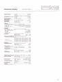
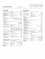
Technische Daten
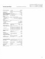
2x3O0W
an 4Ohm:
2x16OW
an SOhm:
1 kHZ-Signal; I Periode ein, 16 Perioden aus
2x2OO\N
Sinusleistung (DlN 45500): an 4 Ohm
2x120\N
an BOhm
Spitzenleistu ng:
Dämpfu ngsfaktor:
>100
bei 1 kHz an SOhm
Harmonische
Verzerrungen:
bei 1 kHz 1B0W an 4 Ohm:
Anstiegszeit:
bei 4Ohm Last
bei BOhm Last
<0.006%
4us
3ps
Eingänge
Empf indl ichköit/l mpedanz : (für l kHz bei 20OW an 4Ohm)
_ TUNER, TAPE 1, TAPE 2, AUX. CD:
250mVl4l kOhm. nominell 50OmV
_ PHONO MM:
2,5mYl47kOhm; 50. 150.450pF; nomrnell 5mV
140pV/10OOhm, nominell 0.5 mV
- PHONO MC (Option):
_ PWR AN/IP.
2.8Vt4t kOhm
Ausgänge
Pegel/lmpedanz:
(bei nomineller Eingangsspannung)
_ FEC, MONITOR, TAPE'1, TAPE 2
- ab Eingang PHONO MM:
PRE.AIVP:
500 mV/440Ohm
250 mV
2,8Y
_ PHONES:
/440Ohrn
9,BV/280 Ohm
28,3V/80 mOhm
_ SPEAKERS A/B:
(parametrisch in +4 Stufen)
BASS bei 40 Hz:
-12d8...+12d8
TREBLE bei 14kHz:
-12d8...+12d8
Fremdspannungsabstand: (bei nomineller Eingangsspannung)
_ TUNER, TAPE1, TAPE2, AUX, CD:
bei 200 W an 4Ohm.1 kOhm Abschluss: 98dB
bei 50mW an 4Ohm,1 kOhm Abschluss: 76dB
_ PHONO MM:
bei 200 W an 4Ohm.1 kOhm Abschluss: 76dB
bei 50mW an 4Ohm, 1 kOhm Abschluss: 75 dB
bei 200 W an 4Ohm. 1 kOhm Abschluss: 73 dB
- PHONO MC (Option)
bei 50mW an 4Ohm. l kOhm Abschluss: 70dB
Klangregler:
Maximale
Eingangsspannung:
IUNER. TAPE1. TAPE2, AUX.
PHONO MM:
PHONO MC (Option):
CD:
10V
200mV
10mV
Ubersprechen:
-
zwischen den Eingängen
Vor /Hinterband:
bei 10 kHz.
bei 10 kHz.
1
1
kOhm Abschluss
kOhm Abschluss
100 dB
BO dB
Kanaltrennung:
TUNER, TAPE
1,
TAPE 2 AUX, CD:
_ PHONO:
bei 1 kHz. 1 kOhm Abschluss:
bei 1 kHz. 1 kOhm Abschluss:
Frequenzgang:
20Hz...2akHz
+0
PHONO R|A,A-Entzerrung: 4 Zeitkonstanten, 20 Hz...20
Stromversorg u ng:
86 dB
55 dB
dB/
kHz
0.2 dB
t0.3
dB
intern einstellbar
100. 120.
140.200.220. 240V AC, + 5%l-10%
50 Hz...60 Hz
Netzsicherung:
100V
140VAC:
200v ...240v
Leistu ngsaufnah me:
maxrm
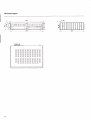
Abmessungen:
in Standby ca
(BxH xT):
Gewicht:
AC.
T6.3A/250v
(SLOW)
T3.15A/250V (SLOW)
BOOW
a l:
10w
450 x109
x
332 mm
15 kg
Anderungen vorbehalten.
27
Abmessungen
EE
28
_
EEEEEEE
EEEEEE
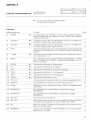
KAPITEL 5
f-rn-f-r-fn t---r--__l fl
Liste der Tastenfu n ktionen
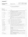
Ku
rzbesch reibung
aller Funktionen
.t))
Mit der lR-Fernbedienung REVOX B20B
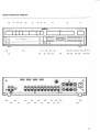
fernsteuerba re Funktionen
Frontseite:
Bed ienungselement
Seite
Funktion
t1l
PowER
it))
Ein-/Ausschalter. Der Verstärker wrrd im zuletzl gewählten BetriebsModus eingeschaltet. Ein weiteres Drücken schaltet den Verstärker
wieder aus (Standby).
l2l
VOLUME +
.r))
Lautstärke erhöhen. Mit ) in 1 dB-schritten und mlt
ten. Beim Programmieren Pegel erhöhen.
t3l
VOLUME
t4l
OPEN
t5l
t6l
10
Lautstärke absenken. Mit( in 1 dB-schritten und mit( in 3 dB-Schritten. Beim Programmieren Pegel absenken.
Empfänger. Die Klappe kann zum Schliessen einfach hochgehoben
werden.
-20d8
3t))
t8l
CD
tel
AUX
t10l
TAPE 2
TAPE
10
1
l12l TUNER
I13] PRE_OUT
+ [2].
10
Nur in Verbindung mit der Ouellen-Erweiterung REVOX 8200' Controller
aktiv. Ermöglicht das Anwählen zusätzlicher Signalquellen wie TV,
VCR\12 und DISC.
.r))
.t))
or))
1t))
.t))
.l))
11
Jedes Drücken dieserTaste senkt das Volumen um 20 dB ab. Rückstellen mir voLUME
VIDEO
PHONO
1l
.t))
in 3 dB-Schrit-
Offnet die Abdeckklappe zum zweiten Tastenfeld und beinhaltet den lR-
t71
t1
-
)
10
Signalquellen-Wahltaste für Plattenspieler.
Signalquellen-Wahltaste für CD-Spieler.
Signalquellen-Wahltaste für den Reserve-Eingang
Signalquellen-Wahltaste für Tonbandgerär2
Signalquellen-Wahltaste fürTonbandgerät
1
Signalquellen-Wahltaste fürTuner.
LED signalisiertden eingeschaltetenVorverstärker-Ausgang
PRE-OUT.
114)
REMOTE
LED signalisiert den Empfang von lR-Fernsteuer-Signalen
t15l
Display
20stelliges Vacuum-Fluoreszenz-Display. Zeigt den Betriebszustand
des Gerätes.
I16]
SPEAKERS B
1
1
24
LED signalisiert den eingeschalteten Lautsprecher-Ausgang
SPEAKERS B.
11
LED signal isiert den eingescha lteten La utsprecher-Ausgang
SPEAKERS A.
11
PHONES
Anschlussbuchse für Kopfhörer.
11
t19l
REC-OUT
Die Aufnahmequelle entspricht nicht der gehörten Ouelle. Das Display
l20l
MC
l21l
SEPARATED
l17l
tl
Bl
SPEAKERS A
[15] ändert die Anzeigeartz.B. auf: lN:TUNER
REC:TAPE1.
13
Wahl des Moving Coil-PHONO-Vorverstärkers bei vorhandener MCOption, ansonsten inaktiv.
14
Trennen von Vorverstärker und Endverstärker. um
dazwischen zu schalten.
1
z.
B. einen Equalizer
5
29
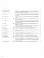
Seite
Bed ienungselement
Funktion
122]
Schaltet den Programmier-Modus für die Eingabe der maximalen Lautstärke (MAX VOLUME) der einzelnen Ausgänge und der EinschaltLautstärke (PWR ON-VOLUME).
17
Die Aufnahmequelle entspricht der gehörten Ouelle. Das Display [15]
ändert die Anzeigeart auf: Signalquelle, Lautstärke und Balance-Stellung.
13
Multifunktionales Anzeigefeld mit den Anzeigen für: BASS, TREBLE,
MAX VOLUME, SENSITIVITY usw.
11
Verringert den Anteil der tiefen Frequenzen. Beim erstmaligen Drücken
wird die aktuelle Einstellung angezeigt.
12
Schaltet den Programmier-Modus für die Eingabe einer LautstärkeVerschiebung zugunsten eines Ausganges und der Empfindlichkeit
(SENSITIVITY) der Signalquellen-Eingänge.
18
Erhöht den Anteil der tiefen Frequenzen. Beim erstmaligen DrÜcken
wird die aktuelle Einstellung angezergt.
12
Schaltet die lautstärkeabhängige Anhebung der tiefen Frequenzen bet
geringer Lautstärke (LOUDNESS-Funktion) ein und aus.
12
Schaltet den Klangsteller (BASS, TREBLE) ein und aus.
12
Verschiebt den Ausgangspegel zugunsten des linken Kanals
12
Verringert den Anteil hoher Frequenzen. Beim erstmaligen Drücken
wird die aktuelle Einstellung angezeigt.
12
Verschiebt den Ausgangspegel zu Gunsten des rechten Kanals.
12
Erhöht den Anteil hoher Frequenzen. Beim erstmaligen Drücken wird
die aktuelle Einstellung angezeigt.
12
Schaltet den Vorverstärker-Ausgang PRE-AMP ein und aus.
11
Schaltet die Lautsprechergruppe SPEAKERS A ein und aus
11
l23l
MAX VOLUME
REC:rN
l24l
LC-Display
l25l
BASS
-
o
r))
126l sENSrlvlrY
1r))
l27l
BASS +
l28l
LOUDN
l2s)
TONE
l30l
BALANCE L
t31l
TREBLE
l32l
BALANCE
t33l
TREBLE +
t34l
t35l
PRE-OUT
R
SPEAKERS A
.t))
.r))
1t))
3t))
3r))
3t))
.t))
Speichertaste. Sch liesst einen Prog rammiervorgang m it MAX VOLUM E
oder SENSITIVITY (ausser SENSITIVITY INPUT) ab. Durch Schliessen
136l sroRE
l37l
30
SPEAKERS B
ot))
der Abdeckklappe kann ein Programmier-Vorgang ohne Abspeicherung jederzeit abgebrochen werden.
16
Schaltet die Lautsprechergruppe SPEAKERS B ein und aus.
11
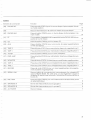
Rückseite:
Bed ienungselement
Funktion
t38l
Eingangs-Buchsen (CINCH) für einen Plattenspieler mit Moving CoilAbtastsystem (Option).
PHONO MC
Masse-Anschluss für
t3el
d
ie Plattenspieler-Erd ung.
Eingangs-Buchsen (CINCH)
für einen
Plattenspieler
mit
Moving
t40l
PHoNo MM
1411
PF
142)
CD
Eingangs-Buchsen (CINCH) für einen CD-Spieler.
t43l
AUX
Eingangs-Buchsen (CINCH) für eine zusätzliche
Eingang).
l44l
t45l
TAPE 2
Eingangs-Buchsen (CINCH) für die Wiedergabe ab Tonbandgerär2.
TAPE
Eingangs-Buchsen (CINCH) für die Wiedergabe ab Tonbandgerät
146l
rUNER
l47l
PWR-AMP
t48l
Magnet-Abtastsystem.
14
Schalter zur Anpassung der Eingangskapazität des PHONO MM-Einganges an die Kapazität des
Plattenspielers.
1
MONTTOR
14
S
14
rgnalquelle (Reserve-
1
Eingangs-Buchsen (CINCH) für einen Tuner (Empfänger).
Eingangs-Buchsen (CINCH) für eine direkte Einspeisung in die Lei-
stungs-Endstufen.
1
5
Ausgangs-Buchsen (CINCH) mit festem Pegel für einen zusätzlichen
Verstärker.
l49l TAPE 2
l50l TAPE
t51l RECORD
l52l SERTAL LrNK
1
Ausgangs-Buchsen (CINCH) für Aufnahmen mit Tonbandgerät 2.
Ausgangs-Buchsen (CINCH) für Aufnahmen mit Tonbandgerät
1.
Ausgangs-Buchsen (CINCH) für einen zusätzlichen Aufnahme-Kanal.
Serieller Steueranschluss für den Anschluss eines externen lR-Empfän-
gers REVOX 8206. Über diese Buchse kann auch der interne
lR-
Empfänger ausgeschaltet werden (Pin 1 mit Pin 2 und Pin 4 mit Pin 5 verbinden).
t53l
PRE-AMP
Ausgangs-Buchsen (CINCH) für den Anschluss von Aktiv-Lautsprecherboxen (Vorverstä rker-Ausgang).
l54l
SPEAKERS A
Lautsprecher-Klemmen der Lautsprechergruppe A
t55]
t56l
SPEAKERS B
Lautsprecher-Klemmen der Lautsprechergruppe
AC POWER
Netzanschluss
B
JI
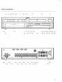
Übersichtszeichnung
E
REMOTE
tlet I t21l lt23l
t18t l2ol
t22l
I
SYSTEM
t251 t27l t2el t31l t33l t35l t37l
t26l
t28)
t3ol
t32l
t34l t36l
32
_
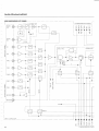
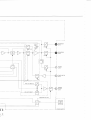
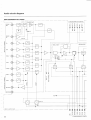
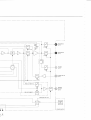
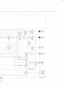
Audio-Blockschaltbild
AUDIO BLOCKDIAGRAM ITEFT CHANI{ELI
L __
I
r
r
PHONO
I
[
--l
--_pp1gNö
f----;l r:f----l-'ll
t\
I
ul,rril
TO IV]ICROCOMPUTER CONIROL
J
F
l
L
Mt\i
z
E
F
l
L
z
E
L
U
F
a
?
V
I
I
V
J
U
2l
<t
co
TI
OI
lLl
lz
loz
IF
J
zzU
T
t<
l--
l(J
I
O
'E
f,
u
J
</)
F
f
oF
l
O
RECORD
t\40NtTOR
I
Lr\PUr -ouTPUT
UNrl_
I
*las:<zt
<(-)O
!lFl=OFC)
JJ
TO I\4ICROCOIV]PUTER CONTRI
_l
SPEAKERS B
(LrFT)
PHONES
(LEn-)
POWER AMP IN
(LEFT)
L1---l--------------J
i_.--.
et
ru_
1
PRE OUT WITH TC
SPEAKERS PRE OUT
POWER
FAIL
DETECT
ENGLISH
O
perating nstructions
I
REVOX 8250
18250-5 ' Amplifier
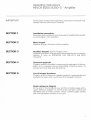
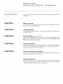
IMPORTANT
For the sake of clarity these operating instructions have been subdivided into the following 5 Sections:
SECTION
nstal lation proced u re
Describes the procedures to be followed for installing the amplifier and putting it into operation.
1
I
SECTION 2
Main keypad
sEcTroN 3
Auxiliary keypad (behind hinged cover)
SECTION 4
Technical appendix
Explains all main functions of the amplifier.
Explains all auxiliary and special functions that are not covered in
Section 2, such as SPEAKERS AlB, PRE-OUT, and MAX
VOLUME.
Contains useful information concerning the operation of the amplifier, error messages and corresponding corrective action, as
well as technical data and dimensions.
SECTION 5
List of keypad functions
Contains a quick-reference operating guide for experienced and
professional users and a summary of all keypad functions.
O.uick-reference d iag ram
At the end of this handbook you will find a foldout page with a
quick-reference diagram on which all the operator controls are
identified with an index number. These numbers agree exactly
with the bracketed numbers in the text
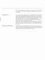
Protectyour amplifierfrom exposure to excessive heat and moisture. lnstall it in a position where the ventilation louvers are not
obstructed.
WARRANTY
PACKING MATERIAL
A special warranty request card is included with all equipment
sold within the Federal Republic of Germany. This card is located
either inside the packing or in a plastic pouch attached to the outside of the packing. Should this card be missing, please consult
your REVOX dealer or your national REVOX distributor.
Warranty cards for equipment sold in Switzerland or Austria are
issued directly by the authorized dealer.
Please note that the warranty is only valid within the country in
which the equipment has been sold. The warranty becomes null
and void if unauthorized modifications or unprofessional repairs
are made.
Please retain the original packing material for reuse in case your
unit ever needs to be transported. The packing in which you received it has been especially designed to protect your valuable
equipment from mechanical shock in transit.
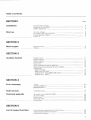
Table of contents
SECTION
Page
1
lnstallation
Accessories included
Setting up the amplifier
Safety regulations
Staft-up
AC Llne voltage
Connecting the stgnal sources
Connecting the outputs
Power on
sEcroN
2
Main keypad
(l
Signal sources
Volume
10
Hinged cover
Signal outputs
Stereo balance
Tone control
Recording
11
11
SECTION 3
Auxiliary keypad
12
12
13
Phono cartridge systems (MM,MC)
Separating the preamplifier/power amplifier
Adjustments:
_ MAX VOLUME
_ PWR-ON VOLUME
- SENSITIVITY:
-
SPEAKERS, PRE-OUT
SENSITIVITY: INPUT
14
1R
16
17
1B
19
SECTION 4
Error messages
OVERLOADED ! !
BREAKDOWN III
!
21
21
21
Fault sources
Troubleshooting
22
Technical appendix
lR remote control REVOX B20B
AC line voltage
24
26
26
Power fuse
sEcfloN
Technical data
Dimensions
27
Ouick-reference description of all functrons
ndexed quick-reference diagram
Audio block diagram
29
28
5
List of keypad functions
I
2)
33
SECTION
1
[rn-[rTn r---r--r E
lnstallation
Scope of supply
Accessories included.
setting up the amplifier
In addition to the amplifier itself, the package
should contain these operating insLructions
and a power cable with a plug of thetype used
in your country. lf the contents are incorrect,
please consult your dealer.
These operating instructions are also available in the following languages:
DEUTSCH:
FRANQAIS:
Setting up the amplifier
Bestellnummer:10.30.0710
No.
comm.:
10
30.0730
Set up your amplifier in a position where the
ventilation louvers are not obstructed. Allow a
ventilation clearance of at least 10 mm
(% inch) from other equipment. walls and furniture.
Safety precautions
Connect the amplifier to the AC outlet by
means of the enclosed power cable.
Always keep the amplifier in dry condition. lt is
extremely hazardous to operate it in moist
conditions (bathroom, laundry room, base-
ment, etc.).
The amplifier is NOT disconnected from the
AC power source when it is switched off
(standby). Certain components inside the unit
are always energized with line voltage!
The amplifier is designed to be operated in a
horizontal position.
ln case of a malfunction or a defect, immediately disconnect the power plug and have the
amplifier checked out by an authorized
REVOX dealer.
4
Ll::oo--l
::__
I
lL_l
Checking the line voltage,
connecting the signal source
Start-up
Checking the line voltage
E---
o
@
o
#
Do
E
Connecting the signal sources
oo
@
11
o
B
I
N/ake sure thatthe voltage rating inscribed be-
low the power inlet [56] agrees with your local
line voltage.
The amplifier can be switched to a different
line voltage but this work should be performed by your dealer.
Make sure that all components to be connected to the amplifier are switched off, or even
better disconnected from the AC power
source.
Connectthe audio outputs (OUTPUT) ofthese
components (signal sources) such as tuner,
CD player, and tape deck to the corresponding inputs of the amplifier.
An additional CD player, a third tape recorder,
or a second tuner can be connected to the auxiliary input AUX [43]
Do not confuse the channels left (L) and right
(R)
o
Tuner. CD,
E---
@;g
o
rn
tU
o
Connectthe outputs of a tuner (radio receiver)
or CD player to the inputs TUNER [46] or CD
142l
CD Player
Turntable
o
----
@
-+
o
l-t
tLJ
o
Connect the turntable outputs to the corresponding PHONO t3B/401 inputs of your amplifier.
lf your turntable is equipped with a stranded
wire, the latter sh ou ld be co n n ected to
the ground terminal [39]
Turntables with a conventional moving magnet cartridge system should be connected to
the terminal marked MM l40l while thosewith
a moving coilcartridge system should be connected to the terminal marked MC [38]. lf an
MC cartridge system is used the amplifier
must be retrofitted with an MC preamplifier
(option).
g ro u n d
Tape recorders
"
@^+
o
lr-l
TJ
o
Two tape recorders can be connected to the
amplifier. Connect the tape recorder outputs
to the TAPE 1 [45] and TAPE 2 [44] inputs of
the amplifier.
For making recordings, the tape recorder inputs must be connected to the corresponding
amplifier outputs TAPE 1 [50] and TAPE 2 [49]
tr
r-TTT[-r-m [---r----l
Start-up
t]
Connecting the outputs, power-on
Speakers
/-l
o
IU
o
Two speaker pairs can be connected to the
goldplated speaker terminals SPEAKERS A
[54] and SPEAKERS B [55] of the REVOX
8250 ' amplifier.
Speakers with an impedance of 4 Ohm or B
Ohm should preferably be used.
Connect only the terminals of like color between the amplifier and the speakers (correct
phasing).
The ground terminals (black terminals) of the
individual speakers must not be interconnect
ed.
ln order to minimize power loss to the speakers. Use cables with a large conductor crosssection. 12 gauge wire can be easily connected to the terminals. Conventional banana plug
(diam.4mm) can be connected directly.
Active speakers
I
:---
@-+
o
r-l
LU
o
Active speakers (with built-in amplifiers)
should be connected to the PRE-AMP [53]
output of the preamplifier.
This output is activated when you press the
PRE-OUT [34] key (behind the hinged cover).
When connecting active speakers, limit the
maximum cable length to the value recommended in Lhe relevant operating instructions
and use only well-shielded audio cables.
TAPE 1 [50], TAPE
2l4s)
o
E
MONITOR
"
Power Amplifier
C)
@^*
o
Eo
The outputs TAPE 1 [50] and TAPE 21491 are
reserved forthe recording paths ofthe recorders TAPE 1 and TAPE 2. When a tape recorder
operates in play mode, the record output of
the corresponding unit is disabled so that
TAPE COPY from one recorder to another is
possible without leedback.
An additional tape recorder or an additional
amplifier can be connected to the MONITOR
l48l output. These units will not be affected by
the volume, tone, and balance controls.
This output always carries the signalfrom the
source that is also audible via the amplifier
outputs (SPEAKERS A/8, PREAMP).
t--Tr-Tr-T-r-n
r--T----l fl
Connecting the signal source,
Start-up
power on
The input of an additional tape recorder, for
example. can be connected to the RECORD
RECORD [51]
[5'1 ] output.
This output always carries the recording signal selected with REC-OUT [19]
Caution:
When you use this output make sure that no
audio loop is created (feedback), (e. g. play
TAPE 1 and simultaneously record on TAPE
via the RECORD output).
1
Tape 3
Power connection [56]
Switching on the amplifier
o
E:::
@
:g
o
Eo
l--rnT-r-m [---r----l I
When all audio connections have been established (signal sources and speakers connected), you can connect the amplifier to an AC
power outlet by means of the enclosed power
cable.
When you press the POWER [1] button on the
front panel. the REVOX 8250 ' Amplifier
switches on and the signal source thatwas ac
tive when the amplifier was switched off the
last time is automatically selected. Pressing
the POWER [1] button a second time switches
lhe amplilier oll (slandby).
When the amplifier is switched off but stlll
connected to the AC power source, it operates in standby mode which means that
it
can
by
be conveniently switched on and off
means of an infrared remote controlfrom your
llstening position.
The power consumption in standby is negligible (approx.'10W).
SECTION 2
EE_
Main keypad
TUNER
1121,
CD t8l, AUX tgl
TAPE 1 [1 1], TAPE
PHONO [7]
Signal sources, volume
2l10l
When you press one of these keys the corresponding input is connected to the amplifier.
The selected signal source together with the
current VOLUME and BALANCE setting are
indicated on the display [15].
The amplifier can also be switched on directly
by selecting a signal source.
When you press one of these keys the corresponding TAPE 1 [45] or TAPE 2 [44] input is
connected to the amplifier. The selected signal source together with the currentVOLUME
and BALANCE setting are indicated on the
display l15l
The amplifier can also be switched on directly
by setting a signal source.
When you press one of these keys the turntable is connected to the amplifier. The select-
ed signal source identified by the word
PHONO together with the current VOLUME
and BALANCE setting are indicated on the
display [15].
The amplif ier can also be switched on directly
by selecting a signal source.
Main keypad
voLUME
+l-
l2l3l
Volume
When you press the VOLUME + [2] key the
volume increases while VOLUME - [3] de-
creases the volume.
The volume can be changed at two different
speeds. lf you press the key below the marking ( and ), the volume changes slowly in
small steps (1 dB). lf you press the key below
the markings (and ), the volume changes
rapidly in larger steps (3 dB).
The actuated VOLU N/E key ((, ) or(, )) is
shown on the display [15] in place of the
BALANCE setting
During the power on phase the volume can be
decreased but not increased.
The maximum achievable volume depends
on the MAX VOLUME set for the corresponding speaker group.
lf both speaker groups are activated, the lower
of the two preset maximum volumes is applicable.
-
20dB tsl
When you press this key the volume is decreased by 20dB in a single step. Press this
key again and the volume is decreased by
another 20 dB. etc. until the minimum volume
is reached.
The volume can be increased by pressing the
VOLUME + [2] key
Note:
'Amplifier is equipped for
future applications. In conjunction with the
REVOX 8200 ' Controller which to can be installed below the amplifier the VIDEO [6] key
can be used to access the secondary func
tions TV. VCR 1. VCR 2, and DISC.
Your REVOX B25O
In this way you can connect the audio signals
of a television set (TV). two video cassette re-
corders (VCR
1, VCR
2J and a DISC player to
your hi-fi system Corresponding video signals of these four sources can be connected
to a monitor (television set) by means of the
controller.
10
SECTION 3
f-rn-rT-fn [---r---_] E
Auxiliary keypad
f-frrr*rTn
l-_---r---l fl
l::3T::
= lLT .
Hinged cover
SPEAKERS AIB
Hinged cover,
signal outputs
l35l37l
EETf EOEI
rlEr--ir-rEO
EOE
f-rrfr-r-rn [--T----l f]
The tinted acrylic glass cover of the second
keypad can be opened by pressing the OPEN
[4] key The LC display l24lwill light up.
In order to close the cover simply push it back
up until it locks into place The illumination of
the display switches off. Any programming
operation left incompleted in the secondary
keypad will be cancelled and the previous
condition reestablished.
When you press the SPEAKERS A 135l key the
speaker group switches on or off. The SPEAKERS B [37] key controls the speaker group B.
ln order to prevent annoying switching clicks
the microprocessor briefly switches the volume off and on again.
Both speaker groups can be switched on or ofi
concurrently.
The green LED [17] to the right of the display
[15] lights up when SPEAKERS A [54] are
switched on; LED [16] indicates the state of
SPEAKERS B [55]
PHONES [18]
f-rrT-f-r-m-E
-IIEE
-ttDo-
PRE-OUT t34l
lume can be controlled with the VOLU ME +/
[2/3] keys
lf no speaker group is switched on, the maximum adjustable volume is determined by the
MAX VOLUIVE set for PHONES. Otherwise
the MAX VOLUME setforthe activated speaker group (or the lower value if both groups are
switched on) ls applicable.
EED-EOC]
--f----1 r----rIE
- Et-
f-TT]-r-r-rn
The headphones can be used in any mode.
Simply plug the headphones into the corresponding socket on the front panel. The vo
---r----l E
-tt-- looo
'I
a l.l ö
When you press the PRE-OUT [34] key the
PRE-AN/P [54] output of the amplifier is
switched on or off
As is the case for the outputs SPEAKERS A/B
1541551, the microprocessor switches the volume off forthe duration of the switching process. This output can be switched independently of the two speaker groups A and B. The
green LED on the left hand side of the display
[15] lights up when the preamplifier output is
activated.
11
Auxiliary keypad
[-rTfr-r-fn ---T----r
Stereo-Balance,
Tone Control
BALANCE LIR 130132)
f_]
With the two keys BALANCE L [30] and BAL-
tt
ANCE R [32] you can match the stereophonic
sound pattern to an asymmetric listening po-
sition by emphasizing one or the other channel
Both channels can be adjusted in steps of
+9
dB. When you press one of these keys, the
current BALANCE setting is automatically displayed for a few seconds by a bargraph on the
display [1 5]
The true balance can be restored as follows:
Continuously press the key of the de-emphasized channel. The adjustment stops automatically in the center position.
The TONE [29] key switches the tone controls
(BASS. TREBLE) on or off so that the sound
can be compared between linear (unin
fluenced) and corrected frequency response.
The current status of this function is shown on
the display ['1 5] for a few seconds: TONE
CONTROL ON/OFF, and the bar symbols for
BASS and TREBLE light up on the LC display
TONE f29l
124)
The LOUDNESS function is automatically
cancelled when this function is selected.
BASS
+l-
TREBLE
l27l25l
+l- l33l31l
T]EE
IIEEEÜEEr-1 f--1EE
EEEIIOE
tlrlr-- r--r-E
With the treble control you can emphasize
E EI-
EEEEEDE
-lr---r--rEE
The LOUDNFSS [28] key activates or deacti
vates the tone compensated volume control
which is matched to the natural characteristics of the human ear.
Based on the maximum volume set with MAX
VOLUN/E, lhe bass lrequencies are accentuated at reduced volumes (1 correction step
per'10 dB of VOLUME decrease).
When the LOUDNESS function is activated,
the manualtone controls (BASS, TREBLE) are
automatically switched off. Conversely the
LOUDNESS function is cancelled when you
press the TONE l29l key.
LOUDNESS [28]
VOL
PHONES
SPEAKERS
PWR ON
dB
-1m
PRE OUT
SPEAKERS
LOUDNESS
PHONO
12
MC
PROGRAM SEPARATED
INPI ]T
With the bass control you can emphasize
(BASS + [27]) or de-emphasize (BASS t25l)
frequencies in 4 steps.
When you press one of the bass control keys
the current setting is shown on the display
l1 5l for a few seconds and the bar symbols for
BASS and TREBLE light up on the LC display
124). Each time you press one of these keys
the setting changes by an additional step in
the corresponding direction.
+ [33]) or de-emphasize (TREBLE 131l) in 4 steps.
When you press one of the treble control keys
the current setting is shown on the display
[1 5] for a few seconds and the bar symbols for
BASS and TREBLE light up on the LC display
1241. Each time you press one of these keys,
the setting changes by an additional step in
the corresponding direction.
(TREBLE
Auxiliary keypad
Record (REC:lN, REC-OUT)
Recording
There are two ways of making a recording.
The audible signal source can also be the re
cording source or a different source can be
selected for recording.
REC:rN [23]
This setting is selected before the amplifier
leaves the factory The display ['1 5] shows the
selected signal source. the volume control
and balance settings. The audible signal
source is also the recording source available
on the outputs RECORD [51],TAPE1 [50], and
TLPtr lLc)1
Note:
'
The outputs TAPE 1 f45l and TAPE 2144) are
mutually interlocked.
If TAPE 1 is defined as the signal source, the record output TAPE 1 [50] is disabled in order to
prevent feedback. Howevet the signal can be
recorded via TAPE 2.
REC*OUT [19]
When you press REC-OUT [1 9] the content of
the display [15] changes immediately.
The word lN: isfollowed bythe currently audible signalsource (e. g TUNER) Forthe record
output a signal source can now be selected
following REC: (e. g PHONO) As a result you
will hear the signal source TUN ER via the outputs SPEAKERS A [54]. SPEAKERS B [55],
PRE-AMP [53], and MONITOR [48]. whilethe
PHONO signal can be recorded via the outputs TAPE 1 [50]. TAPE 2 149), and RECORD
t51 l
13
r-TTff-r-m [---r----r ff
Auxiliary keypad
Phono cartridge system (MM, MC)
a MM (moving
rnagnet) cartridgesystem must be connected
to the PHONO MM [40] input.
Correct matching of the PHONO input is es
sential for optimum reproduction of records.
The input capacitance must, therefore, be adjusted to the cartridge system with the PF [41]
switch located on the rear panel.
Turntables equipped with
N/M
Exception:
When a REVOX 829'1 turntable is used, always
select the 150 pF setting
For cartridge systems Elac EMM 150 and
Matching procedure:
Shure V15V the correct setting is 150pF The
setting of other systems can be computed according to the example given below. The capacitance rating can be found in the technical
specifications of the turntable and the phono
cartridge system.
Example:
Nominal capacitance
of phono cartridge:
Capacitance of turntable
output (cable capacitance)
Correct setting:
375 pF
:
-225pF
150pF
lf the correct value cannot be set exactly. use
the closest possible value. A lower setting
causes accentuation of the (extreme) treble
frequencies, a higher value causes losses in
the (extreme) treble range.
MC t20l
r----rc=
EEEEEEE
IDO
EEr----lr---loE
PHONES
SPEAKERS
PWR ON
!rt!r&!rrr ilrrig'lrl
* aÄss + - TsrBL!:
"1-
V
PHONO
14
dB
25
VOL
MC
PROGRAM
SEPARATED
PRE OUT
SPEAKERS
NPUT
Turntables equipped with a MC (moving coil)
cartridge system should be connected to the
PHONO MC [38] input, but in this case the am-
plifier must be fitted with the optional
N/lC
preamplifier.
When you press the MC t20l key, the MC
preamplifier
is switched on and the MM
preamplifier is switched off
r-rnT-r-m [---r----l E
Auxiliary keypad
SEPARATED [21]
Separating the
preamplif ierlpower amplifier
E]ET--IT--TEI
EIE
vol
PHONES
-1m
odB
-75
ttttt$tit
* BASS
+
trrrletttl
-
TtlgBLE +
PFIE.OUT
SPEAKERS
INPUT
SPEAKERS
V
PWR ON
PHONO
MC
PROGRAM SEPARATED
The SEPARATED [21] key disconnects the
preamplifier from the power amplifier. This is
acknowledged on the LC display 124) by an
arrow pointing to the word SEPARATED.
This function can be used, for example. to
connect an equalizer into the signal path. The
preamplifier signal is available on the PREAMP [53] output (selectable with the PREOUT [34] switch) and fed via the equalizer and
the PWR-AMP [47] input to the power amplifier.
PWR-AMP [47]
voL
PHONES
SPEAKERS
PWR ON
-s
-1m
0
-25
raNrlxrril
rrNr!8rirr
_
_
BASS
+
TREBLE
+
V
PHONO
MC
PROGRAM SEPARATED
dB
PRE'OUT
SPEAKERS
INPTJT
The PWR-AM P [47] input connects the available signal directly to the power amplifier
which means that it can no longer be in-
fluenced with the VOLUME keys.
This input is only enabled when the preamplifier is separated from the power amplifier
(SEPARATED
[21] key).
15
rrn-|--l-fn ---r----l E
Auxiliary keypad
Adjustments: MAX VOLUME
The maximum adjustable volume can be de-
MAX VOLUME l22l
fined individually for SPEAKERS A,
SPEAK-
ERS B. PREAN/P and PHONES
The following procedure must be followed for
each of the outputs. The other outputs should
be switched off. lf more than one output is
switched on the adjustment is made for
SPEAKERS A
O Press SPEAKERS A [35] key
O Press the MAX VOLUME l22l kev
O Press the VOLUME key
O Press the STORE [36] key
Factory setting
OEf
E
EEI
EEE EE ID
tlE r-r r---1 cf cl
Switch on the output to be adjusted by pressing the corresponding key (for PHONES [18]
all outputs must be switched off).
EEECf EEE
EE r-- r--- E E
When you press the IVAX VOLUME l22l key,
the input mode is activated. This is signalled
on the LC display l2al bv a bargraph symbol
for the current setting and the message MAX
VOLUME flashes. The two arrows polnt to
PROGRAM and PHONES or SPEAKERS.
The desired maximum volume can now be set
with the VOLUI\4E + [2] and VOLUN/E [3]
keys.
E======-E
-
EEE
EEEEEEO
E-r---il-rEI
When you press the STORE [36] key, the volume setting is stored as the maximum avail
able volume for the corresponding speaker
group.
A higher volume can only be achieved by increasing the MAX VOLUI\4E according to the
foregoing procedure.
EOEEECf E
EEf----il--l OI
The MAX VOLUME and PWR ON VOLUIVIE
EEI
s
voL -rm
odB
lt{tllilllt I I il! I I * ! I I M I ;
PHONES
SPEAKERS
PWR ON
PRE OUT
< MAX VOLUME
PHONO
VOL
PHONES
SPEAKERS
MC
PROGRAM
SEPARATED
75
-lm
-25
-50
ililllNllt* ! t iti i ! | : ; I t M
0
dB
t
PRE OUT
< MAX VOLUME
V
PHONO
16
SPEAKERS
INPUT
V
MC
NOMINAL
PROGRAM
SEPARATED
SPEAKERS
INPUT
settings made by the factory prior to shipment
of the unit can be reestablished at any time as
follows:
Repeatedly press the MAX VOLUME l22lkey
until the message RESTORE NOMINAL? becomes visible on the LC display [15] and the
flashing message MAX VOLUIVE NON/INAL
appears on the LC display i241.
When you press the STORE [36] key at this
point. the factory settings are reprogrammed
for all outputs.
rrnt--rr-n r---r----l E
Auxiliary keypad
Adjustments: PWR-ON VOLUME
The POWER-ON VOLUME defines the vo-
PWR-ON VOLUME
lume setting at the time the amplifier
is
switched on, regardless of the volume setting
in effect when the amplifier was switched off.
The power-on voiume can also be adjusted to
personal requirements. However, this setting
should not be adjusted to high (power-on at
late hours of the night!).
E--EEOB
O Press MAX VOLUME [22] key
E-r----1 r----rcD
-EI
VOL
75
dB
25
lltl:l|tll| i I Lt I N I I t, I | ! t I
PRE OUT
PHONES
SPEAKERS
PWR ON
MÄX VALUMT
<
PHONO
VOL
MC
-1m
{
O Press STORE [36] key
Factory setting
-50
-25
; I I t lll I I t I | | ? |
0
Y
MC
dB
|
},14X 1IOLUME
PHONO
O Press VOLUME key
PROGRAM SEPARATED
-75
ttü]ll]
PHONES
SPEAKERS
PWR ON
SPEAKERS
INPUT
Y I\'&M'NAI
hl{:}Miru.Al
PRE'OUT
SPEAKERS
INPUT
PROGRAM SEPARATED
rrn-r-r-rnIE
EED
Repeatedly press the MAXVOLUIVE l22lkeV
until the arrow in the LC display f 24l points to
PWR ON. The input mode for entering the
PWR-ON VOLUME is now activated.
On the LC display [24] this is acknowledged
with a bargraph symbol and the flashing message MAX VOLUME. The two arrows pointto
PROGRAN/ and PWR ON.
EDDEEEO
o Df----r f----r-I
The desired power-on volume can now be
set by means of the VOLUME + [2] and
VOLUME
-
f3l keys.
When you press the STORE [36] key the
volume setting is stored as the PWR-ON
VOLUME
You can reprogram the power-on volume at
any time.
The factory settings for MAX VOLUME and
PWR-ON VOLUME can be reestablished at
any time:
Repetitively press the MAX VO LU N/ E l22l key
until the message RESTORE NOMINAL? becomes visible on the LC display [15] and the
flashing message N/AX VOLUME NOMINAL
appears on the LC display [24].
When you press the STORE [36] key at this
point, the factory settings are reprogrammed
for all outputs.
17
f-T-tl-rTr-n [---r--__l
Auxiliary keypad
L_]
Adjustments:
SENSITIVITY: SPEAKERS. PRE-OUT
With the SENSITIVITY key it is possible to adjustthe preamplifier output level relative to the
output level of the SPEAKERS A/B outputs
and to increase or decrease the nominal output level of one speaker group relative to the
other group.
In addition the gain of the input amplifier can
be matched to the levels of the individual signal sources.
sENSrTrVrrY t26l
lf several outputs are simultaneously active,
the nominal output level is governed by the
output with the highest priority:
1st priority: SPEAKERS A
2nd priority: SPEAKERS B
No priority: PRE-OUT
Each input and output can be adjusted individually.
O Press SPEAKERS A [35] key
EIEE
-ECf EEII
OEET-IE
Activate the output to be adjusted by pressing
the corresponding key. Switch-off the other
outputs (PRE-OUT. SPEAKERS B).
- -Et
EEEEEC]Tf
l Er----1 r----l-E
The SENSITIVITY [26] key activates the input
mode. On the LC display [24] this is acknowledged with a bargraph symbolforthe current
setting and the flashing message SENSITIVITY The two arrows point to PROGRAM and
O Press SENSITIVITY [26] key
VOL
lll]
iN,:l,lll
ttttttttr
o
PHONES
SPEAKERS
PWR ON
+
SENSITTVITY
PRE-OUT
>
V
PHONO
O Press VOLUME key
da
-75
-100
MC
PROGRAM SEPARATED
The level of the activated output can now be
increased or decreased by means of the
VOLUIVE + f2l and VOLUME - [3] keys.
[-rn-rr-mEE
loooooo
VOL
1M
odB
-75
!ll]
o
PHONES
SPEAKERS
PWR ON
O Press STORE 136l key
Factory setting
1B
EEE
tllttt!'tt
+
SENSITIVITY >
Y
PHONO
MC
SPEAKERS.
SPEAKERS
INPUT
PRE.OUT
SPEAKERS
INPUT
PROGRAM SEPARATED
EDE EEEE
clEr---lr-r-I
When you press the STORE [36] key the volume setting is stored.
You can reprogram the level at any time.
The factory sensitivity setting can be reestab-
lished at any time.
Repeatedly press the SENSITIVITY [26] key
until the message RESTORE NOMINAL? becomes visible on the LC display [15] and the
flashing message SENSITIVITY NOMINAL
appears on the LC display [24]
When you press the STORE 136l key at this
point, the factory settings are reprogrammed
for all inputs and outputs.
f-rTT[-r-rn r---r--_-l ff
Auxiliary keypad
SENSTTTVTTY
Adjustments.
INPUT SENSITIVITY
With the SENSITIVITY key it is possible to ad-
t26l
just the prea mplif ier output level relative to the
output level of the signal sources.
Each input is individually adjustable.
O Press TUNER [12] key
rrfl--r-rn
l--ll---Lrn-----l
E
---r--__l
O Press SENSITIVITY [26] key
voL
If iI t IxI l,]llI
PHONO MC
VOL
PHONES
!IIi,
-ü
I
PRE OUT
SPEAKERS
INPUT
PROGRAM
75
-Tm
l.
SPEAKERS
I I I t iI'
-ü*
PHONES
SPEAKERS
PWR ON
dB
-25
-10o
!ll't!
O Press STORE [36] key
EEE
tt
to be adjusted
(TUNER, TAPE 112, AUX,CD,PHONO. TV, VCR
1/2. DISC) by pressing the appropriate key
Repeatedly press the SENSIIIVITY [26] key
until the arrow on the LC display [24] points to
INPUI This activates the mode for entering
the sensitivity of the inputs. On the LC display
[24] this is acknowledged with a bargraph
symbol for the current setting and the flashing
rnessage SENSITIVITY The two arrows point
to PROGRAM and INPUT.
SEPARATED
-25
It I:Il I1
0
dB
PRE OUT
SPEAKERS
iNPUT
PWR ON
PHONO
Select the signal source
MC
PROGRAM SEPARATED
OOEET]EE
=----a
When you press the STORE [36] key the level
measurement is automatically activated for
the corresponding input. When you release
the STORE [36] key the gain of the corresponding input amplifier is matched to the
measured level and stored.
During the measurement operation the mes
sage MEASURING appears on the display
l'1
5l behind the signal source. lf the signal
source does not supply a signal or if the signal
is too low (switched off), the message LOW
LEVEL appears and the gain of the input amplifier is not changed
Factory setting
The factory sensitivity setting can be reestab-
lished at any time:
Repeatedly press the SENSITIVITY [26] key
until the message RESTORE NOMINAL? becomes visible on the LC display [15] and the
flashing message SENSITIVITY NOMINAL
appears on the LC display [24].
When you press the STORE [36] key at this
point, the factory settings are reprogrammed
for all inputs and outputs.
19
SECTION 4
f-T-I-T-Tr-n [---r----l
Fault messages
OVERLOADED
!I!,
f]
BREAKDOWN !!I
The volume is automatically decreased by
10 dB if the temperature of the output power
stages becomes too high.
This process is indicated on the display ['1 5]
symbol in place of the
by the flashing ((
ba lance setting. The volume can be f urther decreased with the VOLUME keys, but not in
indication disapcreased until the ((
pea rs.
After the output power stages have cooled off
the display [15] returns to the usual format.
i. e. the signal source and the recording
source, or the signal source. volume and balance settings are shown. The volume can now
be increased as desired. However, the cause
for the fault message (possibly insufficient
ventilation) should be investigated.
,
OVERLOADED
II
I
E r]f]EEIT
EEE
EEf----1
r----
lf the output power stages do not cool off after
message has been displayed and
the ((
their temperature continuous to increase, the
fault message OVERLOADED !!l is shown on
the display [1 5] and the speaker outputs are
switched off
After the output power stages have cooled off
and the message has disappeared. the speakers can be switched on again by pressing the
keys SPEAKERS A i35l and/or SPEAKERS B
137)
BREAKDOWN !!!
In the event of severe overloading (e. g. manipulation of the connectors while the amplifier
is switched on and the volume is all the way
up), the speakers are muted. This fault is indicated by the message BREAKDOWN lll on
the display [15].
To remedy this fault, switch the amplifier off,
check that all cables and connectors are firmly seated. and switch the amplifier back on aJter a reasonable pause.
a1
LI
r-T_fff-r-m r-T--__l Ll
-ll-- looa
'I
Fault control
Troubleshooting
Before you suspect a fault in the amplifier,
make sure that the unit is correctly installed
and that it is being operated in accordance
with these instructions.
Check the speaker connections.
Speakers are deaci
Has the speaker group been switched on
(with SPEAKERS A [35], SPEAKERS B [37],
PRE-OUT [34])?
Has the power amplifier been SEPARATED
from the preamplifier? Press the SEPARATED
[21] key again
Has any signal source been selected and
switched on?
lnsufficient output power
-r--r----ln
r--'r
rl-'l
DEI
Tf
if EE-EE
r-rEI
Has the MAX VOLU N/E been inadvertently set
too low? You can check this bV reestablishinq
the factory setting (RESTORE NOMINAL?).
EE)r---1
No reproduction in PHONO mode
@
l-]
IU
o
E
Has the turntable been connected to the cor
rect PHONO input (MM [40] or MC [38])?
Has the correct cartridge system been select-
ed on the amplifier (press N/lC [20] key for an
MC cartridge)?
[-rn-rT-m [---r---]
Recording on TAPE not possible
'
@-+
B
11
n
o
Bo
Are the INPUTS of the tape recorcier connected to the OUTPUTS TAPE 1 [50] or TAPE 2
l4el?
The amplifier cannot be operated
t-lE
!
EEE
EEEEEEE
EEr---il-] ECI
Your amplifier is controlled and monitored by
a microprocessor. When Iine voltage is applied this microprocessor is automatically initia lized.
Faults in the AC supply system and otherfaults
can putthe microprocessor into an undefined
state. The amplifier can no longer be operated.
The microprocessor can be restarted by pressing the RESET button above the SEPARATED
121) key by means of a pointed object (bent
open paper clip).
Since the circuit conditions of the audio paths
cannot be monitored during the reinitialization
process, the speakers should preferably be
disconnected from the amplifier.
lf the power plug is readily accessible, it is better to disconnect it from the AC outlet for ap-
prox. 15 seconds rather than actuating the
RESET button.
During the initialization of the microprocessor
certain segments of the display [15] may
briefly light up. This is a normal process and
does not damage the amplifier.
23
if l\
ti"""""tl
lm::":l
Itrtr ntrtrl
.".-."1
Technical appendix
lR remote control
REVOX B20B ' Remote Control
nncaoal
."."."1
loEo-ll
with the REVox B20B infrared remote control
REVOX B2OB
you can conveniently control the audio functions of the complete REVOX hi{i system from
your listening position.
.IIUU
- I looo
In addition to the functions of the main keypad
of the REVOX 8250 amplifier, you can remote
control the outputs SPEAKERS A, SPEAKERS
B, PRE-OUT. the BALANCE setting and the
tone control functions (TONE, BASS.
TREBLE)
O
perating characteristics
--r
With the lR remote control the amplifier can
be operated in the same manner as on the unit
itself, except for the following special cases.
Power on
The amplifier can only be powered on with the
lR remote control by selecting a
(TUNER APE112, AUX. CD, PHONO)
source
lf you press the POWER OFF key on the lR re-
mote control, all REVOX lR-equipped components in the entire hi-fi system will be switched
off.
TV VCR 112, DISC
The additional signal sources accessible with
' Controller are activated
with the remote control by pressing the x key
the REVOX B2O0
together with the corresponding source se
lection key.
24
lf the
REC_OUT
amplifier is operating in REC-OUT mode
(REC-OUT [19] key). the signal source to
which you are currently listening can also be
the recording source by pressing the REC:
MON key on the lR remote control.
You can then press a source selection key for
listening
to
another signal source without
changing the recording source.
voLUME
+/-
When you briefly press the VOLUME key on
the lR remote control, the volume is changed
in small steps (1 dB), if you hold down this key
continuously the volume changes in larger
steps (3 dB).
25
|--rnTr-[n r--r----l
Technical appendix
Changing the line voltage
n
Line voltage, power fuse
The amplifier can be switched over to different line voltages but this work should be performed by your dealer!
Disconnect the power cordl
Remove the top cover and the left-hand side
panel.
Lift the protective foil and adjust the line voltage.
Glue a rating label that corresponds to the
new line voltage overthe 220V- marking below the power inlet on the rear panel.
Power fuse
lf the line voltage setting is changed, the power fuses must be checked and matched to the
new line voltage, if necessary.
100.. 140VAC: 6.3Ai250V (SLOW)
200...240v AC: 3.154/250V (SLOW)
Completely reassemble the unit before you reconnect it to the AC power outlet.
26
f-TT]-r-n-n t---r--__l tl
r r ::"-:;;
Technical appendix
Technical data
IHF standards
IEG standards
Peak output power:
into 4Ohm:
into 8 Ohm:
'l kHz signal;
2x3O0W
2x160W
1
Harmonic distortion:
Rise
time:
into 8 Ohm
at 1 kHz into
I
Ohm
at 1 kHz, lBOW into 4 Ohm
for 4 Ohm load:
for B Ohm load:
Dynamic headroom:
> 100
<0 006%
4!rs
Frequency response:
3 !,s
(for l kHz at 200W into 4Ohm)
Sensitivity/impedance:
_ TUNER, IAPE 1, TAPE 2 AUX, CD:
250mY/41 kOhm. nominal 500mV
2.5mV/47kOhm; 50, 150.450pF; nominal 5mV
PHONO MM:
140pV/10OOhm. nominal 0.5mV
PHONO IVC (option):
_ PWR_AMP:
2.BY/41 kOhm
Outputs
(at nominal input voltage)
l/impedance:
REC, MONITOR, TAPE'1 TAPE2:
from PHONO MM input
500 mV/440 Ohm
250 mV
_ PRE_AMP:
_ PHONES:
2.BY/440Ohm
9.8V/2BO Ohm
28.3V/80 mOhm
SPFAKERS A/B:
Tone control response:
(parametnc in +4 steps)
BASS at 40 Hz:
TREBLE
Signal-to-noise-ratio:
-12d8...+12d8
-12d8...+12d8
aI14k1z
linear(atnominalinputvoitage)
_ TUNER, TAPEl, TAPF2, AUX, CD:
-
PHONO MM:
PHONO MC {option)r
at 200 W rnto 4Ohm, l kOhm termination: 98dB
at 50mw rnto 40hm, l kohm termination: 76dB
at 200 w into 40hm. 1kohm termination; 76dB
at 50mW rnto 4 Ohm. 1 kOhm termination: 75 dB
at 2OO W into 4Ohm. l kOhrn termination: 73dB
at 50mW lnto 4Ohm. 1kOhm termination; 70dB
Maximum input voltage: TUNER.
10V
TAPE'1, TAPE 2, AUX, CD
200 mV
1O mV
PHONO MM:
PHONO IVC {option):
Crosstalk attenuation:
-
Between inputs:
Tape/source:
at 10 kHz. 1 kOhm termination:
at 1O kHz. 1 kOhm termination:
äö:;
Channel separation:
Sensitivity:
- PHONO:
at 1 kHz. 1 kOhm termination:
at 1 kHz. lkOhm termination:
Frequency response:
20Hz...20kHz
86 dB
55 dB
+0
dB/
0.2 dB
-
Power requirements:
internaily adjustable
100.120.140.200 220 240V AC, +50/o/-10%
50 Hz...60 Hz
Power fuse:
100v..140vAC
200v ...240v AC
Power consumption:
maxrmum:
in standby. approx
Dimensions:
Weight:
(WxHxD)
a
pp rox
+0
dBl- /0.2d8
+03dB
250 mV
2.5 mV
140pV
PHONO MM:
PHONO MC (option):
POWEFAMP:
2.av
A-weighted
Signal-to-noise-ratio:
refered to 100W at BOhm
AUX, CD:
103 dB
BO dB
75 dB
PHONO MM:
PHONO l\lC (option):
Maximum input signal:
_ TUNFR, TAPE 1, TAPE 2, AUX, CD
_ PHONO MM:
- PHONO MC (option):
10v
200 mV
10 mV
lnput impedance:
_ TUNER, TAPE 1, TAPE 2, AUX, CD
PHONO MM:
- PHONO MC (option):
47 kOhm
47 kOhm; 50. 150, 450pF
100 Ohm
47 kOhm
POWERAMP:
Output impedance:
_ TAPE
1, TAPE
2, REC, MONITOR, PREAIVP
440 Ohm
280 Ohm
80 mOhm
_ PHONES:
_ SPEAKERS A/B:
Damping factor:
Tone-controlresponse:
at 1 kHz referenced to
Crosstalk:
Channel separation:
between inputs at
- ruNER,
rAPE
1.
-APF
I
Ohm
100
-12d8...+12d8
-12d8...+12d8
BASS at 40 Hz:
TREBLE at 14 kHz
1O
100 dB
kHz
2 AUX, CD:
at 1 kHz
at 1 kHz
86 dB
55 dB
Power supply:
internal switch for
100 120.140.20A.220 240V AC, +5%/ -10ya
Power fuse:
100v .140vAC
50Hz.60Hz
200v ...240v AC
PHONO RIAA equalization: 4 times constants. 20Hz...20kHz
1.9 dB
_ TUNER, TAPE"I, TAPE 2 AUX, CD:
Power
+0.3 dB
2 8dB
for 1O0W at SOhm
PHONO
TUNER, TAPE'1, TAPE 2, AUX, CD:
2x'1
at 4Ohm
at B Ohm
2OHz...2OkHz
High level inputs:
PHONO RIAA equalization:
_ TUNER, TAPE'1, TAPE
Leve
2x150W
00W
at 4Ohm:
at I Ohm:
2x200\N
2x120\l,l
lnputs
-
20H2...20kHz. THD <0 015%,
period on, 16 periods off
Continuous power output: into 4Ohm
(DlN 45500)
Damping factor:
Continuous average
Power output:
consumption:
max.
Standby mode
Dimensions:
Weight:
(WxH xD)
approx
T6 3A/250v (SLOW)
r315A/250V
(SLOW)
800w
approx. 10W
450 x 109 x 332 mm
(33 lbs) 15 ks
Subiect to change
A/250V (SLOW)
T3.15A/250V (SLOW)
T 6.3
BOOW
10w
450 x109
x
332 mm
l5 kg
Sublect to change
27
Dimensions
ol
IF
9l."l
tI
+-+
+
l-l
sf lFl
28
EEEEOEE
OEEEEE
--
, ,
ca.28
SECTION 5
f-rn-f-T--m
lndex of keypad functions
r---r--r ff
ick-reference description
of all functions
Ou
1,))
Functions that respond to the
REVOX B20B lR remote control.
Front panel:
Page
Function
Operating element
t1l
PowER
.t))
On/off switch. The amplifier is switched on in the last active mode. The
amplifier is switched off (standby) when this key is pressed again.
t2l
VOLUME +
.r))
lncreases the volume. With ) in 1dB steps, with
lncreases the level in programming mode.
)
t3l
VOLUME
Decreases the volume. With ( in 1dB steps, with
Decreases the level in programming mode.
(
l4l
OPEN
t5l
-20d8
t6l
VIDEO
-
.r))
.t))
in 3dB steps.
10
in 3dB steps.
10
Opens the hinged cover of the auxiliary keypad and contains the lR receiver. To reclose the cover simply push it up.
11
Decreases the volume by - 20 dB each time this key is pressed. Can be
reset with VOLUME + [2].
10
Only active in conjunction with the REVOX 8200 ' Controller. Can be
used for selecting additional signal sources such as TV, VCR 1l2 and
10
DISC.
17l
PHONO
t8l
CD
tel
AUX
t10l
TAPE 2
tl
1l
TAPE
1
3r))
Signal source selection key for turntable
.r))
.r))
.t))
3r))
.t))
Signal source selection key for CD player.
Signal source selection key for the auxiliary input.
Signal source selection key for tape recorder 2.
Signal source selection key for tape recorder
1.
Signal source selection key for tuner.
112)
TUNER
t13l
l14l
t15l
PRE-OUT
This pilot LED is lit when the preamplifier output PRE-OUT is activated.
11
REMOTE
This LED is lit when an lR signal is being received.
24
Display
20-position vacuum fluorescence display. lndicates the operating state
of the amplifier.
t16l
SPEAKERS B
This LED is lrt when the SPEAKERS B output is switched on.
11
1171 SPEAKERS A
This LED is lit when the SPEAKERS A output is switched on
11
Headphones socket.
11
tl
Bl PHONES
119l
REC-OUT
The recording source differs from the listening source. The display [1 5]
changes the indicating mode to
l20l
MC
121)
SEPARATED
e.
g.: lN :TUNER REC :TAPE
1.
1
3
Selects the moving coil PHONO preamplifier if the MC option is installed. otherwise this key is inactive.
14
Separates the preamplifier from the power amplifier so that
equalizer can be looped in.
1
e.
g. an
5
29
Page
Operating element
Function
122) MAX
Activates the mode for programming the MAX VOLUME of the indivldual outputs and rhe PWR-ON VOLUME.
17
The recording source is the same as the listening source. The display
[15] changes the indicating mode to: signal source, volume, and balance setting.
IJ
l23l
VOLUME
REC:rN
l24l
LC display
l25l
BASS
Multifunction display field with indrcators for: BASS, TREBLE, MAX
VOLUME, SENSITIVITY
-
3t))
126l sENSrrvlrY
l27l
BASS +
l2B1
LOUDN
.r))
l29l roNE
t30l BALANCE
t31l TREBLE -
1t))
.r))
.t))
l32l BALANCE R
l33l TREBLE +
.t))
.r))
t34l
t35l
i36l
.r))
o))
t37l
30
PRE-OUT
SPEAKERS A
sroRE
SPEAKERS B
etc.
11
Reduces the content of low frequencies. The current setting ls displayed when you press this key the first time.
12
Activates the mode for programming relative volume levels between all
audio inputs and between speakers pairs. Compensation in favor of an
output and the SENSITIVITY of the signal sources.
1B
lncreases the content of low frequencies. The current setting is displayed when you press this key the first time.
12
Switches the tone compensated volume control (LOUDNESS function)
on and off.
12
Switches the tone control (BASS, TREBLE) on and off
12
Shifts the output level in favor of the left channel
12
Decreases the content of high frequencies. The current setting is displayed when you press this key the first time.
12
Shifts the output level in favor of the right channel.
12
lncreases the content of high frequencies. The current setting is displayed when you press this key the first time.
12
Switches the preamplifier output PRE-AMP on and off.
11
Switches SPEAKERS A on and off
11
Stores the programmed MAX VOLU ME or SENSITIVITY setting (except
SENSITIVITY INPUT). A programming sequence can be cancelled at
any time without storing by simply closing the cover.
16
Switches SPEAKERS B on and off
11
Rear panel:
Function
t38l
lnput sockets (CINCH) for a turntable with moving coil cartridge system
PHONO MC
tQot
WI
t40l
PHoNo MM
l41l
PF
142)
CD
14
lnput sockets (CINCH) for a turntable with moving magnet cartridge
system.
14
Switch for matching the input capacitance of the PHONO MM input to
the capacitance of the turntable.
14
lnput sockets (CINCH) for a CD player.
l43l AUX
l44l TAPE 2
- l45l IAPE
1
-
(option).
Terminal for turntable ground.
LU
_
Page
Operating element
lnput sockets (CINCH) for an additional signal source (auxiliary input).
lnput sockets (CINCH) for playback from tape recorder 2.
lnput sockets (CINCH) for playback from tape recorder
1
146l
TUNER
lnput sockets (CINCH) for a tuner.
l47l
t48l
PWR-AMP
lnput sockets (CINCH) for direct feeding into the amplifier stage
MONTTOR
Output sockets (CINCH) with fixed level for an additional amplifier
t49l
t50l
TAPE 2
Output sockets (CINCH) for recording with tape deck 2.
rAPE
Output sockets (CINCH) for recording with tape deck
15t
I
1
RECORD
15
1
Output sockets (CINCH) for an additional recording channel (third tape
deck).
l52l
SERTAL LrNK
t53l
PRE-AMP
Serial control terminal for connecting an external REVOX 8206 lR receiver.
t54l SPEAKERS A
I55] SPEAKERS B
t56l AC POWER
Output sockets (CINCH) for connecting active speakers (preamplifier
output).
Speaker terminals for speaker group A
Speaker terminals for speaker group
B.
Power connection.
31
Ouick-reference diag ram
n1l tlot
tel
t]
REMOTE I SYSTEM
tlel I t21l lt23l
t18l l2ol
t22l
t25l t27l t2el t31l l33l t35l t37l
t26l
t28)
t3ol
I32l
t34l
136l
JL
Audio circuit diagram
AUDIO BLOCKDIAGRAM ILEFT CHANI{ELI
'lV oPTroN--r
L:.-_I
rl
ul
zt
^^
zILU
+l
(J
f,
U
)
Pl
tt
nux
Il
TAPE 2
fU
z.
z.
T
(J
TAPEl
f,
U
J
a
,
rNPU-r
-OuTPUr
UN|I_ _
itJ
Hla
s<OO
u
EIGA!E
lL
-
.)
=
O
TO IVIICROCOIV]PUTER CONTR(
I
SPEAKERS B
(LEFT)
PHONES
(LEFT)
POWER AMP IN
(LEn-)
l__j ,L__
lpurr
i
t_
PREAIV]P
OUTPUT
(LEFT)
PRE OUT DIRECT
I
_J
I
SPEAKERS PRE OUT
l_1
i
r!
-]3q',t*trttfi
-
FRAN9AIS
Mode d'emploi
REVOX
AVIS
IMPORTANT
8250i 8250-5 ' Amplificateur
Pour plus de clart6, le pr6sent mode d'emploi est partag6 en cinq
chapitres:
_
CHAPITRE
1
-
CHAPITRE
2
clavier principal
CHAPITRE
3
Second clavier (sous le cache)
Contient des explications sur toutes les fonctions auxiliaires et
sp6ciales non d6crites au chapitre 1, par exemple SPEAKERS A/8,
PRE-OUT et MAX VOLUME.
CHAPITRE
4
Annexe technique
rvlise en service
Contient les informations essentielles pour I'installation et la mise
en service de I'amplificateur.
Contient des explications sur toutes les fonctions principales de
l'amplificateur
Contient des informations int6ressantes sur I'utilisation de l'amplificateur, les messages et leur r6paration ainsi que les caract6ristiques techniques et les dimensions.
CHAPITRE
5
Liste des fonctions de touches
Contient un mode d'emploi abr6g6 et donne un rapide apergu de
toutes les fonctions de touches.
Dessin synoptique
A la fin du livre, vous trouverez une page ä ouvrir avec un dessin
rep6r6 de I'appareil. Les repöres dans le texte (entre parenthöses
carr6es) correspondent ä ceux du dessin.
Prot6gez votre appareil de la chaleur et de l'humidit6 excessives.
Montez-le de maniÖre que les fentes d'a6ration ne soient pas couvertes.
GARANTIE
Les appareils vendus en R6publique F6d6rale dAllemaqne sont
accompagn6s d'une cafte sp6ciale de demande de garantie.
Cette carte se trouve soit dans I'emballage, soit dans un sachet de
plastique ä I'ext6rieur de I'emballage. Si cette cafte manquait,
adressez-vous ä votre revendeur sp6cialis6 REVOX ou ä votre repr6sentation nationale REVOX.
Pour les appareils achet6s en Suisse et en Autriche, le certificat de
garantie est remis par le revendeur.
Veuillez noter que la garantie n'est valable que dans le pays de
vente. En outre, nous vous signalons que la garantie est caduque
si l'appareil a fait I'objet d'interventions ou de r6parations non conformes aux rögles de I'art.
EMBALLAGE
Veuillez conseryer I'emballage d'origine. En cas de transporl, cet
emballage sp6cial est la meilleure protection pourvotre pr6cieux
appareil.
Table des matiöres
CHAPITRE
Page
1
lnstallation
Contenu de l'emballage
lnstallation
Prescriptions de s6curit6
4
4
4
Mise en service
Tension du r6seau
Raccordement des SOUTCCS de signal
Raccordement des sorties
Mise sous tension
tr
Ä
b
7
CHAPITRE 2
Clavier principal
o
Sources de signal
Volume
10
Cache
11
11
CHAPITRE 3
Second clavier
Sorties de signal
Balance st616o
R6glage de tonalit6
12
12
13
Enregistrements
Phonocapteur (MM, MC)
S6paration pr6ampl ificateu r/amplif icateu r
14
f
ina
I
15
R6glages:
- MAX VOLUME
- PWR_ON VOLUME
- SENSITIVITY: SPEAKERS,
- SENSITIVITY: INPUT
16
17
PRE-OUT
1B
19
CHAPITRE 4
Messages d'erreurs
OVERLOADED ! I
BREAKDOWN !!I
I
21
21
21
Sources d'erreurs
Erreurs possibles et r6paration
22
Annexe technique
T6l6commande lR REVOX B20B
24
26
26
Tension r6seau
Fusible r6seau
Caract6ristiques techniques
Dimensions
27
28
CHAPITRE 5
Liste des fonctions
Description succincte de toutes les fonctrons
Dessin rep6r6 de l'appareil
Sch6mabloc audio
29
0/_
33
CHAPITRE
1
|--rnT-r-fn [---r----l f]
lnstallation
Contenu de l'emballage
.IIEE
-tt---
Contenu de l'emballage,
installation
Outre le pr6sent mode d'emploi et l'appareil.
l'emballage contient encore un cäble r6seau
correspondant ä la norme nationale. En cas de
problömes, veuillez vous adresser ä votre revendeur sp6cialis6. Le pr6sent mode d'emploi
est 69alement disponible dans les langues
su
ivantes:
ENGLISH:
DEUTSCH
lnstallation
Order No.: 10.30.0720
Bestell-Nr.: 10.30.07'1 0
lnstallez l'appareil de maniÖre que les fentes
d'a6ration ne soient pas couvertes et qu'il y ait
un 6cart de ventilation d'au moins'10 mm par
rapport aux autres appareils. aux murs et meubles.
Prescriptions de s6curit6
Veuillez ne raccorder I'appareil au r6seau
qu'au moyen du cäble rÖseau joint. Maintenez
l'appareil toujours sec et ne l'utilisez jamais
dans des Iocaux humides (salle de bains,
buanderie, cave, etc.). [appareil mis hors tension (Standby) n'est pas coup6 de l'alimentation 6lectrique. Certaines parties ä l'int6rieur
de l'appareil sont toujours sous tension de 16seaul llappareil est congu pour fonctionner en
position normale (horizontale). En cas de
mauvais fonctionnement ou de d6fauts, ilfaut
imm6diatement retirer la fiche du r6seau et re-
mettre l'appareil ä un revendeur sp6cialis6
REVOX pour contröle
4
Mise en service
Contröle de la tension de rdseau
Tension r6seau,
raccordement des sources
E:--
o
E
@
-+
o
Do
V6rifiez que la tension indiqu6e au dessous
du raccord de r6seau [56] correspond ä celle
du r6seau. Si n6cessaire, l'appareil peut ötre
commute sur une autre tens;on. Veuillez confier cette commutation ä votre revendeur sp6cialis6.
Raccordement des sources de signal
@ tffiFf
" E--"8S' ft8pl88la8q @ E
Tuner. CD,
o
Eo
Assurez-vous que tous le sappareils suppl6mentaires de votre chaine hautefid6lit6 sont
mis hors tension ou. mieux encore, coup6s du
rösea u.
Raccordez maintenant les sorties audio (OUTPUT) de ces appareils (sources de signal)
comme le tuner, le lecteur CD et le magn6tophone aux entr6es pr6vues de l'amplificateur.
A l'entröe auxiliaire AUX [43], on peut raccoTder un lecteur CD suppl6mentaire, un troisiÖ
me magn6tophone ou un second tuner.
Veillez ä ce que les canaux gauche (L) et droit
(R) ne soient pas intervertis.
Les sorties d'un tuner (r6cepteur radio) ou lec-
teur CD doivent ötre reli6es aux
TUNER
entr6es
[46] ou CD 142) de l'amplificateur.
Tuner
Tourne-d isque
o
E
Les sorties d'un tourne-disque doivent ötre
raccord6es aux entr6es correspondantes
PHONO t3e/40) de l'amplificateur
Si votre tourne-disque est 6quip6 d'un f il de
masse, celui-ci doit ötre raccord6 ä la masse
t3el
Les tourne-disques ä phonocapteur magn6ti
que doivent ötre branch6s au raccord marqu6
MM
1401. ceux 6quip6s d'un phonocapteur
dynamique (bobine mobile) au raccord MC
[38] Pour cette entr6e l'utilisation avec les
systÖmes de lecture MC. I'amplificateur doit
ötre 6quip6 du pr6amplificateur MC (option).
Magn6tophones
lfl
o
tui
o
Deux magn6tophones peuvent ötre raccord6s ä l'amplif icateur. Les sorties des magn6tophones sont ä raccorder aux entr6es TAPE
[45] et TAPE 2l44l de l'amplificateur.
Pour pouvoir faire 69alement des enregistrements, leurs entr6es doi ötre reli6es aux sorties correspondantes TAPE 1 [50] et TAPE 2
1
[49] de l'amplificateur.
Tape
1
-rm--r-m [---r----l E
Mise en service
Raccordement des sorties
Deux paires de haut-parleurs peuvent ötre
raccord6s aux bornes dor6es SPEAKERS A
l54l et SPEAKERS B [55] de l'amplificateur
Haut-parleurs
REVOX B25O
ll est prö1örable d'utiliser des enceintes acous
tiques d'une imp6dance de 4 Ohm ou B Ohm.
Ne relier entre eux que les raccords de couleur
correspondante entre l'amplificateur et les en-
ceintes acoustiques (phase correcte).
Les raccords wde masse (noirs) des diff6rents
haut-parleurs ne doivent pas ötre reli6s entre
eux.
Pour r6duire les pertes au minimum, utilisez
les cäbles joints aux haut-parleurs ou des
cäbles sp6ciaux de section aussi grande que
possible. Les cäbles jusqu'au diamötre de
4 mm
(
-
12 mmz 1 peuventtacilement ötre rac-
cord6s aux bornes. Les fichesbananes du
commerce l@4mm) peuvent ötre enfich6es
directement.
Haut-parleurs actifs
o
0
o
Les enceintes actives (ä amplificateur incorpor6) doivent ötre branch6es ä la sortie PRE-
AN/P t53l de I'amplificateur.
Cette sortie est activ6e en actionnant la touche PRE-OUT [34] du second clavier (sous le
cache).
Pour les haut-parleurs actifs. la longueur maxi-
male du cäble n'est limit6e qu'aux valeurs recommand6es au mode d'emploi correspondanttant que l'on n'utilise que des cäbles blind6s.
TAPE 1 [50], TAPE
2l49l
o
Bo
Les sorties TAPE 1 [50] et TAPE 21491sont 16serv6es aux circuits d'enregistrement des ma
gn6tophonesTAPE 1 etTAPE 2.Pourla lecture.
la sortie d'enregistrement est coup6e pour cet
appareilafin de permettre une copie de bande
(TAPE COPY) d'un magnötophone ä I'autre
sans interf6rence.
MONITOR
o
:---
@
^+
o
Eo
Un magn6tophone suppl6mentaire ou un second amplificateur peut etre branch6 ä la sortie MONITOR [48], ces appareils n'6tant pas
influenc6s par les 16glage volume, tonalit6 et
balance.
A cette sortie correspond le signal
6cout6
avec l'amplificateur (SPEAKERS A/8, PRE-
AMP) la source de signal audible sur les sorties de l'amplificateur (SPEAKERS A/8, PREAN/ P).
Power Amplifier
6
[-rTl-f-r-m [---r----l E
:Il??r
Raccordement de sorties,
mise sous tension
Mise en service
RECORD [51]
t==1-==
tFr
[5'1 ], on peut raccorder pour I'enregistrement un magn6tophone
LLJJ
suppl6mentaire.
o
o
A cette sortie RECORD
Cette sortie fournit toujours le signal s6lectionn6 par REC-OUT [1 9] ou le signalREC:lN
1231.
l-lEnffr|
Attention:
En se servant de cette sortie, veiller ä ce qu'il
n'y ait pas de boucle audio (interf6rence)
(jouer TAPE 1 et enregistreren möme temps
par la sortie RECORD surTAPE 1)
-ntl
Tape 3
Une fois toutes les connexions audio faites
Raccordement au r6seau [56]
(sources et haut-parleurs raccord6s) l'amplificateur peut Ötre raccord6 au r6seau au moyen
du cäble joint.
t
Mise sous tension
r-rn-f-r-m r---r---_l I
-tt-- | lEoa
0rÄln
En pressant la touche POWER [1] sur la pla-
que frontale de l'appareil,
l'amplificateur
REVOX 8250 est mis sous tension. la source
activ6e au moment de la derniöre mise hors
tension est ä nouveau s6lectionn6e. Une nouvelle pression sur la touche POWER ['1 ] met
l'appareil hors tension (Standby).
[appareil hors tension mais reli6 au r6seau se
trouve ä l'etat de veille. Lappareil peut alors
Ötre mis sous tension et hors tension commod6ment depuis la place d'6coute au moyen de
la t6l6commande infrarouge.
La consommation en veille est n6gligeable
(10W env.).
7
CHAPITRE 2
Clavier principal
TUNER
1121,
CD l8l, AUX tgl
TAPE 1 [1 1], TAPE
2l10l
o
Sources de signal
En pressant une de ces touches. on commute
I'entr6e correspondante.
La source de signal est indiqu6e ä l'affichage
[15] avec le 169lage actuel de VOLUME et la
position de BALANCE.
llamplificateur peut 69alement 6tre enclench6 directement en s6lectionnant la source.
En pressant la touche TAPE 1 [1
'1
] ou TAPE 2
[10], on commute l'entr6e correspondante
2l44l.La source enclench6 est indiqu6e ä l'affichage ['1 5] avec le 16glage actuel de VOLUME et de BALANCE.
llamplificateur peut 6galement ötre enclench6 directement en s6lectionnant la source.
TAPE 1 f45l ou TAPE
PHONO [7]
Commute la table de lecture raccord6e ä l'entr6e PHONO l3B/401.
La source de signal est ;ndiqu6e ä l'affichage
[15] avec le 169lage actuel de VOLUME et la
position de la BALANCE.
llamplificateur peut 69alement Ötre enclench6 directement en selectionnant la source.
Clavier principal
voLUME
-
+l-
20 dB [5]
l2l3l
Volume
Une pression sur la touche VOLUME + [2]
augmente levolume, latoucheVOLUME - [3]
le fait diminuer.
Le r6glage peut se faire ä deux vitesses. En
pressant les touches sous les marques ( et ),
le volume varie lentement par petits pas (1 dB).
En pressant sous les touches ( et )), le volume varie rapidement par grands pas (3 dB).
A I'affichage [15], la position BALANCE est
remplac6e par le symbole de la touche
VOLUME actionn6e ((, ) ou <<, >>)
Durant la phase d'enclenchement de l'amplificateur, le volume peut Ötre r6duit mais non
augment6.
Le volume maximai possible d6pend de la position de IVAX VOLUME pour le groupe de
haut-parleurs enclench6. Si les deux groupes
sont enclench6s. le volume maximal inf6rieur
est d6terminant.
Lamplificateur peut 6galement ötre enclench6 avec les touches VOLUME.
En pressant cette touche, on r6duit le volume
d'un seul coup de 20d8. Une nouvelle pres-
sion r6duit le volume encore une fois
de
20dB, etc. jusqu'au minimum de volume.
En pressant la touche VOLUN/E + i2l. on peut
r6augmenter le volume.
lndication
Votre amplificateur REVOX 8250 est 6quip6
pour une expansion d'entr6es. Avec Ie contröleur REVOX B200 qui se monte sous l'amplificateur, la touche VIDEO [6] donne accös aux
fonctions secondaires TV, VCR1, VCR2 et
DISC
Cela permet de raccorder les signaux audio
d'un t6l6viseur (TV). de deux magn6toscopes
(VCR 1, VCR 2) et d'un lecteur de disque vid6o
(DISC) ä la chaine haute fid6lit6. En outre, les
signaux vid6o des quatre sources peuvent
Ötre commut6s avec le contröleurvers un moniteu r (t6l6viseur) de ma niöre analogue aux si-
gnaux audio.
10
CHAPITRE 3
f-rn-r-r-fn r---r--__l E
Second clavier
Cache
l--T-fn--r-T-l t--T--_-l
I=:
SPEAKERS AIB I35I37I
o
Cache, sorties de stgnaux
EEE)
E
-- =l;=r-
OOE EO-I
E O r-l r---r E D
[-rrrf-r]-n ---l-----l tl
Le cache en verre fum6 du second clavier
s'ouvre en pressant sur la touche OPEN [4].
l'affichage LC l24l est illumin6.
Pou r fermer, il suff it de relever le couvercle jus
qu'au d6clic. L6clairage s'6teint et toute programmation en cours mais non termin6e au
second clavier est coupöe et l'6tat ant6rieur
est r6tabli
A [35], on
enclenche et d6clenche le groupe de hautEn pressant la touche SPEAKERS
parleurs A, en pressant la touche SPEAKERS
B [37] le groupe B Pour 6viter des bruits gönants ä la commulalion. le microprocesseur
coupe en douceur le volume et le r6tablit.
Les deux groupes peuvent ötre enclench6s ou
d6clench6s simultan6ment (PHONES)
A droite, ä cöt6 de I'affichage [15], une LED
verte [17] signale
le
groupe
SPEAKERS A [54] et une LED
enclench6 SPEAKERS B [55]
PHONES
f-TT-rI--r-mIE
[1
enclenchÖ
6] le groupe
L6coute au casque est en touttemps possibie.
ll suff it d'enficher un casque dans la prise p16vue sur la face f rontale. Le volume se rögle au
moyen des touches VOLUIVIE +/- l2l3l
Si aucun groupe de haut parleurs n'est en-
clench6,
Ie MAX VOLUIVIE
16916 pour
PHONES d6termine le volume maximal 169lable. Autrement, c'est le MAXVOLUME pour le
groupe enclench6 qui est valable ou, si les
deux groupes sont enclench6s, le MAX
VOLUN/E inf6rieur.
PRE-OUT l34l
EEE
EEIEOEEI]
oElf----1 f----rIE
f-T-rff-r-fn r---r----l E
=II3-?r l::=T::
En pressant la touche PRE-OUT [34], la sortie
de pr6amplificateur PRE-AMP [53] de l'am-
plificateur est enclenchöe ou d6clench6e.
Comme pour les sorties SPEAKERS A/B [54l
551, le microprocesseur coupe et r6tablit le
volume ä la commutation
Cette sortie peut ötre commutöe ind6pendamment des deux groupes de haut-parleurs
AetB.
A gauche. ä cöt6 de l'affichage [1 5]. une LED
verte ['1 3] signale la sortie de pr6amplificateur
enclench6e.
11
f-T_frT-T--fn r---r--__l
Second clavier
BALANCE LIR l30l32l
Balance st616o,
a
r6glage de tonalit6
Avec les deux touches BALANCE L [30] et
tl
EEE
BALANCE R [32], le son st616ophonique peut
Ötre adapt6 ä une position d'6coute asym6trique en favorisant l'un ou l'autre des canaux.
Les deux canaux peuvent ötre 169l6s de + 9 dB
pas. En pressant l'une des touches. une barre
lumineuse ä l'affichage [1 5] indique automatiquement le 169lage actuel de BALANCE pen
E-II-E
i............................................ii..................................::::......!:::'
roNE [29]
fl
EEEIEEE
--f----r f----'r-fl
E-O
dant quelques secondes.
La compensation de balance peut Ötre 169l6e
ä nouveau comme suit:
Presser continuellement la touche du canal att6nu6, le 16glage s'arrÖte automatiquementen
position m6diane.
La touche TON E [29] enclenche et d6clenche
le 169lage de tonalitö (BASS, TREBLE). Cela
permet une comparaison entre l'6coute lin6aire (sans influence) et une correction 6ventuelle.
A l'affichage [15], l'6tat actuel de cette fonction est affichö pendant quelques secondes:
TONE CONTROL ON/OFF et, ä l'affichage LC
1241, les symboles pour BASS et TREBLE apparaissent pour TONE CONTROL ON.
llenclenchement de cette fonction supprime
la fonction LOUDNESS
BASS
+/-
127
t25)
TIt]OEEE
EE)f----1 E-E
E I]E
Le 169lage des graves permet d'6lever les fr6quences basses ä 4 niveaux (BASS + l21l ou
de les diminuer (BASS - t25l).
En pressant une touche du 169lage des graves, Ie 169lage actuel est indiqu6 pendant
quelquessecondesä I'affichage[1 5] etä l'affi
chage LC [24] apparaissent les symboles
pour BASS et TREBLE. Toute nouvelle pression modifie le r6glage dans les sens coTres-
ponda nt.
TREBLE
+l-
133131)
OOO'IEE
-Er----1 r----rE-
DOC
Le 169lage des aigus permet d'6lever les fr6quences hautes ä 4 niveaux (TREBLE + [33])
ou de les diminuer (TREBLE - t31l)
En pressant une touche du 169lage des aigus.
le 169lage actuel est indiqu6 pendant quelques secondes ä l'affichage [1 5] et ä l'afficha'
Se LC [24] apparaissent les symboles pour
BASS etTREBLE. Toute nouvelle pression modifie le r6glage dans le sens correspondant.
touche LOUDN [28] enclenche et d6clenche le r6glage de tonalit6 en fonction du volume, avec adaptation ä la caract6ristique natu
LOUDNESS l28l
La
VOL
odB
1M
PRE.OUT
SPEAKERS
PHONES
SPEAKERS
PWR ON
LOUDNESS
PHONO
12
MC
PROGRAM
LNPUT
SEPARATED
relle de l'oreille.
A partir du volume maximal
16916 par MAX
VOLUME. cela donne une 6l6vation des fr6quences basses ä volume r6duit ('1 pas de correction par 10 dB de r6duction de VOLUME).
En activant la fonction LOUDNESS, le 169lage
manuel de tonalit6 (BASS, TREBLE) est coup6
automatiquement. Autrement, la fonction
LOUDNESS est supprim6e en pressant la touche TONE f291.
f-rl-]-r-r-fn
Second clavier
Enregistrements
REC:rN t23l
---r--__l f:l
Enregistrements (REC:lN, REC-OUT)
Les enregistrements peuvent se faire de deux
maniöres diff6rentes.
Ou bien la source entendue peut 6tre en möme temps source d'enregistrement, ou bien la
source entendue et la source d'enregistrement peuvent Ötre distinctes.
Ce type d'enregistrement est 169l6 ä la livraison de l'amplificateur. [affichage [1 5] indique
la möme image avec la source s6lectionn6e,
le 169lage de volume et de balance.
La source entendue est en mÖme temps la
source d'enregistrement sur les sorties
RECORD [51], TAPE 1 [50] et TAPE 2 [49]
lnd ication:
[45] et TAPE 2 l44l sontverrouill6es mutuellement.
Si par exemple TAPE 1 est la source, la propre
entr6e d'enregistrement TAPE 1 [50] est bloqu6e pour öviter toute interf6rence. Le signal
peut cependant Ötre enregistr6 avec TAPE 2.
Les sorties TAPE 1
REC-OUT [19]
En pressant la touche REC-OUT [19], l'affichage ['1 5] change imm6diatement.
Aprös le mot lN: on a la source entendue (par
exemple:TUNER) Pour le circuit d'enregistrement, une source (par exemple: PHONO) peut
ötre s6lectionn6e derriöre REC:. De cette maniöre, on peut entendre la source TUNER par
les sorties SPEAKERS A 1541, SPEAKERS B
[55]. PRE-AMP [53] et N/ONITOR l48l et en
registrer la source PHONO par les sorties
TAPE 1 [50], rAPE 2l49l et RECoRD [51].
13
f-TTff-T--[n r---r---t f_]
Second clavier
Phonocapteur (MM, MC)
Les tourne disques 6quip6s d'un phonocap
teur ä aimant mobile MM (moving magnet)
MN/
doivent ötre raccord6s ä l'entr6e PHONO N/N/
t40l
Ladaptation corTecte de l'entr6e PHONO
a
une importance capitale pour une reproduction optimale des disques, la capacit6 d'entr6e doit ötre adaptöe au moyen du commutateur PF [41] ä l'arriöre de l'appareil.
Exception.
En raccordant un lecteur REVOX 8291, il faut
toujours s6lectionner la position 150 pF
Pour les phonocapteurs Elac et EMM 150 et
Shure V15V, il faut r6gler 150pF Le r6glage
Rdglage:
pour d'autres systÖmes est ä calculer selon
l'exemple suvant. Les valeurs de capacit6 doi-
vent etre emprunt6es aux fiches techniques
des fabricants de tourne-disques et phonocapteu rs.
Exemple:
375 pF
Capacit6 nominale du lecteur:
Capacit6 de la sortie
de tourne-disque
(capacit6 du cäble ä soustraire): -225pF
R6glage:
1
50 pF
Si la valeur ne peut ötre 169l6e exactement, on
choisira la valeur la plus proche. Un 169lage
plus bas r6hausse les aigus (extrömes), un 16glage plus haut provoque des pertes dans la
plage (extröme) des aigus.
MC t20l
EEEEEEE
-E r----1 r-r E D
IEE
VOL
s
75
-100
dB
! I I titcl t,1
PHONES
SPEAKERS
PWR ON
t, I I ls,, I I
- 8ÄSS + - T*r$Lr I
V
PHONO
14
MC
PROGRAM
SEPARATED
PRE-OUT
SPEAKERS
NPUT
Les tourne-disques 6quip6s d'un phonocapteur ä bobine mobile MC (moving coil) peu-
vent se raccorder ä I'entr6e PHONO N/C [38]
si l'amplificateur est 6quip6 de l'option
de
pr6amplificateur MC.
En pressant la touche MC [20], le pr6amplificateur MC est enclench6 et le pr6amplificateur MM est mis hors circuit.
r-TT-[r-r-m
Second clavier
SEPARATED [21]
[---r--r
t_]
S6paration du pr6amplificateur
et de l'amplificateur final
EEE-Tf EE
E-r-rr--rol
nlEt
voL
PHONES
SPEAKERS
odB
-1m
lrrilsilil
rrrrlsiilr
_ B,qs$ + - TR€EL€
MC
PROGRAM
le
p16amplificateur est s6pa16 de l'amplificateur
final au niveau interne. Cela est indiqu6 ä
l'affichage LC 124) par la flöche sur le mot
SEPARATED.
+
V
PHONO
En pressant la touche SEPARATED 121),
PRE.OUT
SPEAKERS
LNPUT
SEPARATED
Cette fonction permet par exemple de placer
un correcteur dans le trajet du signal. A la sortie PRE-AMP [53] (commutable avec la touche PRE-AMP l34l). on peut prendre le signal
de pr6amplificateur pour le faire passer par le
correcteur et le r6introduire ä l'entr6e PWRAMP [47] ä l'amplificateur final.
PWR-AMP [47]
vol
PHONES
SPEAKERS
dB
-100
,i!,ldrrrl :!rrlsrlll
* B,qS$ + * TR€BLF +
Y
PHONO
MC
PROGRAM
PREour
:::Yt*"
[entr6e PWR-AIVP [47] applique le signal directement ä I'amplificateur final et n'est plus
influencable avec les touches VOLUME.
Cette ehtröe n'est enclench6e que lorsque le
pr6amplificateur et I'amplificateur final sont
s6par6s (touche SEPARATED [21]).
15
r-rrrr-r-m [---l--__l E
Second clavier
R6glages: MAX VOLUME
Pour les sorties SPEAKERS A, SPEAKERS B.
PRE-AMP et PHONES. le volume maximal 16glable peut ötre introduit s6par6ment.
Pour chacune des sorties, il faut observer Ia
proc6dure de 169lage ci-dessous. Les autres
sorties doivent 6tre coup6es. Si plusieurs sorties sont enclench6es, le 169lage est effectu6
automatiquement pour le groupe de haut-parleurs SPEAKERS A.
MAX VOLU\AE 122]
O Presser la touche
SPEAKERS
A t35l
O Presser la touche
MAX VOLU\AE l22l
EEEEETE
E-E
clEr-1
EIEI
EEECf EEE
E]EEEEE
-clcf
Enclencher la sortie ä 169ler en pressant la
touche correspondante (pour PHONES [18]
totes les sorties doivent ötre d6clench6es).
En pressant la touche MAX VOLUME 1221, on
commute en mode d'introduction. Iaffichage
LC l24l donne une barre pour le r6glage actuel, les mots clignotants MAXVOLUME et les
deux flöches sur PBOGRAM et PHONES ou
SPEAKERS
O Presser la touche VOLUME
tl
E ======
I
l3-?
::.:::
---r
=
O Presser la touche STORE 136l
r----.ll_1
-
R6glage d'usine
EEE
EEETf EBE
ECf T--TEBI
trtEt
EEEEEEE
ED r---r r-1 E !
Avec les touches VOLUME + [2] et VOLUME
- [3], on peut 169ler le volume maximalvoulu.
En pressant la touche STORE [36]. on m6morise le volume 169l6 comme volume maximal
permis pour ce groupe de haut-parleurs.
Un volume plus 6lev6 ne peut ötre 16916 ä nouveau que lorsqu'un MAX VOLUIVE sup6rieur
a 6t6 16916 comme ci-dessus.
Les 169lages d'usine ä la livraison de I'appareil
pour MAX VOLUME et PWR ON-VOLUME
peuvent Ötre refaits en tout temps:
la touche MAX
VOLUME [22] jusqu'ä ce qu'apparaisse ä l'affichage [15] RESTORE NOMINAL? et ä l'affichage LC [24] le signe clignotantMAXVOLU
ME NOIVINAL
En pressant la touche STORE [36], le r6glage
d'usine pour toutes les sorties esi ä nou"veau
Actionner plusieurs fois
voL
-s
-r0o
llill]tilt
PHONES
SPEAKERS
PWR ON
-100
3::^t-ä"
rNPUr
MC
PROGRAM
-75
-50
SEPARATED
-25
| llt ! | I i I I I I i I
0
dB
I
PRE OUT
< MAX VOLUME
V
PHONO
16
i
V
ill]llllll,
PHONES
SPEAKERS
PWR ON
odB
< MAX VOLUME
PHONO
VOL
-25
N, ]It I I I ; I I t I I I
MC
NOMINAL
PROGRAM SEPARATED
SPEAKERS
INPUT
PrOgramme'
r-lr-ft--T--m r---r----l
Second clavier
fl
R6glages: PWR-ON VOLUME
PWR_ON VOLUME (POWER ON_VOLUME)
PWR-ON VOLUME
indique
le
volume auquel l'appareilest enclen-
ch6, quel que soit le 169lage deVOLUME auxquel il a 6t6 d6clench6.
Ce 169lage peut 6galement ötre adapte aux
besoins individuels. ll est recommand6 de ne
pas le choisir trop haut (enclenchement pendant la nuit).
O Presser la touche
MAX VOLUME l22l
EEC]DE-C]
EFr----r-EE
-Et
illltIillli'
PHONES
SPEAKERS
PWR ON
N
lrt ! I I I I N I I I |
|
PRE-OUT
MÄX VOLIjMä
<
SPEAKERS
INPUT
? t\ioM,NAt
PHONO
VOL
dB
-25
VOL
*1m
MC
PROGRAM
-75
-50
ll,ftltl'lt tMilt
SEPARATED
-25
0
{
tl
Presser la touche VOLUME
O Presser la touche STORE 136l
Y tlSMrtrlAL
MC
PROGRAM SEPARATED
-rrl-|-r-m-E
:ll--l=
EOE
le volume ä I'enclenchement (PWR ONVOLUME).
Ceci est indiqu6 ä I'aff ichage LC l24l par une
barre pour le 169lage actuel et le slgne clignotant MAX VOLUIVE et les deux flöches sur
PROGRAM et PWR ON.
PRE-OUT
SPEAKERS
INPUT
MAX VOLUM€
PHONO
Cela commute en mode d'introduction pour
t,IM!]|
PHONES
SPEAKERS
dB
Presser plusieurs fois la touche MAX VOLUMEl22)jusqu'ä ce que la flöche de l'affichage
LC l24l indique PWR ON.
Avec les touches VOLUME + [2] etVOLUN/E
- [3] on peut alors r6gler le volume d'enclen-
------l
OC]DFEEDOT- T:E]I
chement voulu.
En pressant la touche STORE [36] le volume
169l6 est m6moris6 comme volume d'enclenchement (PWR ON-VOLUN/E)
On peut en tout temps programmer un autre
volume d'enclenchement.
R6glage d'usine
Les 169lages d'usine ä la livraison de l'appareil
pour MAX VOLUME et PWR ON-VOLUME
peuvent Ötre refaits en tout temps:
Actionner plusieurs fois la touche MAX
VOLUME [22] jusqu'ä ce qu'apparaisse ä l'affichage [15] RESTORE NOIVINAL? et ä l'affichage LC [24] le signe clignotant MAX VOLUME NOMINAL
En pressant la touche STORE [36]. le 169lage
d'usine pour toutes les sorties est ä nouveau
programm6.
17
rrrrr-T--[n t---r--r
Second clavier
f_]
R69lages:
SENSITIVITY: SPEAKERS, PRE-OUT
Avec SENSITIVITY (sensibilit6) on peut faire
varier le niveau de la sortie de pr6amplifica-
sENStrvrrY 126)
teur PRE-AMP par rapport au niveau des sorties de haut-parleurs SPEAKERS A/B et augmenter ou diminuer le niveau nominal de sortie de l'un des groupes de haut-parleurs par
rapport ä l'autre.
En autre, l'amplification des amplificateurs
d'entr6e peut ötre adapt6e aux niveaux des
diff6rentes sources de signal.
Si plusieurs sorties sont enclench6es simultan6ment, le niveau nominal de la sortie de plus
haute priorit6 est activ6:
priorit6: SPEAKERS A
2e priorit6: SPEAKERS B
Pas de priorit6: PRE-OUT
1re
Le 169lage se fait pas ä pas. individuellement
pour chaque entr6e et pour chaque sortie.
O Presser la touche
SPEAKERS
A t35l
EEEEEII
EEr----lElE
OEIE
La sortie ä r6gler est enclench6e en pressant
la touche correspondante. Les autres sorties
(PRE-OUT, SPEAKERS B) doivent ötre mises
hors circuit.
O Presser la touche
SENSTTTVTTY 126)
EEECf EEE
I-f----r r----r-E
E-E
dB
-75
VOL
IIIMIii!]]INIiNMI
PHONES
SPEAKERS
PWR ON
-0+
V
PHONO
O Presser la touche VOLUME
SENSITIMTY >
MC
PROGRAM SEPARATED
[-rrrf-r]-nEE
:Il;;f
vol -lm
Il
PHONES
SPEAKERS
PWR ON
O Presser la touche STORE [36]
R6glage d'usine
EEEI
l;;:;;;
Avec les touches VOLUME + [2] et VOLUME
- [3] on peut relever ou diminuer le niveau de
la sortie enclench6e.
oda
r I' I I ilNt' I
-0+
Nr!
i I;II
I
PRE OUT
SENSITIVITY >
Y
PHONO
PRE.OUT
SPEAKERS
INPUT
En pressant la touche SENSITIVITY [26] on
commute en mode d'introduction. A l'affichage LC 124) cela est indiqu6 par une barre pour
le 169lage actuel et le signe clignotant SENSITIVITY ainsi que les deux flöches sur PROGRAM et SPEAKERS.
MC
SPEAKERS
INPUT
PROGRAM SEPARATED
EEE EEED
cEf---rr---1 -I
En pressant la touche STORE [36] on m6mori'
se le niveau 169lö
Un autre niveau peut Ötre programm6 ä tout
moment.
Le 169lage d'usine ä la livraison de l'appareil
pour les sensibilit6s peut Ötre refait en toul
temps:
Actionner plusieurs fois la touche SENSITIVITY [26] jusqu'ä ce qu'apparaisse ä I'affichage [15] RESTORE NOMINAL? et ä I'affichage
LC 124) le signe clignotant SENSITIVITY NOMINAL
En pressant la touche STORE [36], le r6glage
d'usine pour toutes les entr6es et sorties est ä
nouveau programm6.
1B
f-ITrT-T--fn [---r--___l f_]
Second clavier
R69lages:
SENSITIVITY: INPUT
Avec SENSITIVITY (sensibilit6) on peut adapter I'amplification des amplificateurs d'entr6e
aux niveaux des sources.
Le 169 lage se f ait s6par6ment pour chaque en-
SENSTTTVTTY 126)
tr6e.
O Presser la touche TUNER t12l
O Presser la touche
SENSTTTVTTY t26l
r]-r[-r-rn
E
--]---__l
E-T]EEEE
I--C]E-
EOE
voL -rm
[24] indique
!i:M!li!]],N]Ittt*I
PRE OUT
PHONES
SPEAKERS
PWR ON
Si:i!SlTiVlTY
PHONO MC
VOL
PHONES
SPEAKERS
R69lage d'usine
EET]
PROGRAM
!MIi!!!!11]IN!llll
-*+
tt
MC
SEPARATED
-25
75
-1m
PHONO
O Presser la touche STORE [36]
SPEAKERS
INPUT
v>
0
pressant la touche correspondante.
Presser plusieurs fois la touche SENSITIVITY
[26] jusqu'ä ce que la flöche ä l'affichage LC
dB
-25
S6lectionner ia source ä 169ler (TUNER, TAPE
112. AUX, CD, PHONO. TV, VCR 1/2, DISC) en
NPUT.
Cela commute en mode d'introduction pour la
sensibilit6 des entr6es.
Cela est indiqu6 ä I'affichage LC l24l par une
barre pour 169lage actuel et le signe clignotant
SENSITIVITY ainsi que les deux flöches sur
PROGRAM et INPUT.
dB
{
PRE OUT
SPEAKERS
INPUT
PBOGRAM SEPARATED
T]OEEI]EE
En pressant la touche STORE [36] on active
une mesure automatique de niveau de l'entr6e
correspondante.
En lächant la touche STORE [36] l'amplification de l'amplificateur d'entr6e est adapt6e au
niveau mesu16 et m6moris6e.
Pendant la mesure, N/EASURING apparait ä
I'affichage [1 5] aprös la source de signal. Si la
source de signal ne donne pas de signal ou un
signal faible (coup6) le message LOW LEVEL
apparait et I'amplification de l'amplificateur
d'entr6e reste inchang6e.
Le 16glage d'usine ä la livraison de l'appareil
pour les sensibilit6s peut Ötre refait en tout
temps:
Actionner plusieurs fois la touche SENSITI-
VITY [26] jusqu'ä ce qu'apparaisse ä l'affichage LC 124) le signe clignotant SENSITIVITY
NOMINAL
En pressant la touche STORE 1361. le 169lage
d'usine pour toutes les entr6es et sorties est ä
nouveau programm6.
10
CHAPITRE 4
f-TTff-r-fn
-tt!!
'I
Messages d'erreurs
OVERLOADED
I!!,
E
---r---r
looo
BREAKDOWN II!
En cas d'6chauffement excessif des 6tages fi-
f-TTrr-r-rn r-----_l
E
-IILU
-tt-oo
nals de puissance. le volume est diminu6 automatiquement de 10 dB.
Ceci est indiqu6 ä l'affichage [15] par le symbole clignotant <<<< ä la place de l'indication de balance. Le volume peut encore ötre
r6duit avec les touches VOLUME, mais ne
peut plus ötre augmentö avant que s'6teigne
l'aff ichage
Aprös refroidissement des ötages de puissance, on a ä nouveau l'affichage normal [15] de
la source et de la source d'enregistrement ou
la source et les 169lages de volume et de balance. Le volume peut ä nouveau ötre augment6 ä volont6. La cause du d6faut doit
cependant ötre examin6e et supprim6e (ventilation insuffisante).
OVERLOADED
!I
Si les 6tages de puissance ne refroidissent
I
pas aprÖs le message
((
mais continuenl
de s'6chauffer. on a le message OVERLOA-
E
BREAKDOWN
E]-
EEEET]I'
-Er--"rr----1EE
I!I
DED
!!!ä
l'aff ichage [1 5] et les sorties de haut-
parleurs sont coup6es.
Aprös ref roidessement et disparition du message. les groupes de haut-parleurs doivent ä
nouveau 6tre enclench6s avec les touches
SPEAKERS A [35] et SPEAKERS B I37].
En cas de surmodulation extröme (par exem-
f-TT-[r-T--m [---r--__l
.IIEE
-tt--ö löl .
r
ple manipulation aux fiches ä l'appareil
enclench6 et volume ouvert ä fond) les haut
parleurs sont coup6s. Ceci est signal6 ä l'affichage [15] par BREAKDOWN I ll.
Mettre I'appareil hors tension. supprimer les
causes possibles (cäbles et fiches d6tach6s)
et remettre l'appareil sous tension aprös un
certain temps de repos.
21
T-rl-T-rT-m r---T----r r_l
Sources d'erreurs
Erreurs possible et r6paration
Avant de supposer un d6faut dans l'appareil, il
faut s'assurer qu'il est raccord6 correctement
et que la manoeuvre est conforme ä la proc6dure du mode d'emploi.
Contrölez le raccordement des enceintes.
Le groupe de haut-parleurs est-il enclench6
Pas de son dans les haut-parleurs
(touches SPEAKERS
A [35].
SPEAKERS
B
PRE-OUT l34l)?
[amplificateur final est il s6pa16 du pr6amplificateur (SEPARATED)? Presser ä nouveau la
touche SEPARATED 1211.
Une source signal est elle s6lectionn6e et en1371.
clench6e?
Amplification insuffisante
Pas d'6coute du PHONO
C]ODEEEE)
-Ef----r f----'rEI
DEI
o
@
E
B
@
MAXVOLUME a-t-il6t6 16916 trop bas par m6garde? M6moriser ä nouveau le 169lage d'usine pour contröle (RESTORE NON/INAL?)
Le tourne-disque est-il raccord6e ä l'entr6e
correcte PHONO (MN/ l40l ou MC [38])?
Est-il correctement s6lectionn6 ä l'amplificateur (presser la touche IVC t20l seulement
pour un phonocapteur MC)?
r-T-f[rT-m [---r--_-l f]
Enregistrement impossible sur TAPE
Les entr6es du magn6tophone (INPUT sur le
magn6tophone) sont-elles reli6es aux sorties
OUTPUTS TAPE 1
22
[50] ou TAPE 2 l49l?
[appareil ne peut ötre command6
r---rE
I
EEE
EECIEEEO
EEr---il-] ECI
llamplificateur est command6 et surveil16 par
un microprocesseur. En appliquant la tension
du r6seau. le microprocesseur s'initialise au-
tomatiquement.
Des perturbations du r6seau peuvent mettre
le microprocesseur dans un 6tat ind6fini et
l'appareil ne peut plus ötre command6.
En pressant la touche RESET au-dessus de la
touche SEPARATED [21] au moyen d'un objet
pointu (agrafe de bureau) on fait red6marrer le
rocesseu r.
Etant donn6 que les 6tats des circuits audio ne
peuvent ötre surveill6s, il est pr6f6rable de
m rc rop
couper les enceintes de I'amplificateur.
S i la fiche r6seau est bien accessible, il est p16f6rable de la retirer de la prise de courant briÖvement (15 secondes environ) au lieu d'actionner la touche RESET.
Si certains segments de l'affichage [1 5] s'allu-
ment briövement pendant l'initialisation du
microprocesseur, cela est d0 au systÖme et ne
pr6sente aucun danger pour l'appareil.
23
Annexe technique
REVOX B2OB
T6l6commande
REVOX B2OB
.
IR
Remote Control
Avec la t6l6commande lR REVOX B208, vous
pouvez t6l6commander confortablement depuis votre position d'6coute les fonctions de
toute votre chaine haute fid6lit6 REVOX.
Outre les fonctions du clavier principal de
l'amplificateur REVOX 8250. les sorties
SPEAKERS A, SPEAKERS B, PRE-OUT, le 16glage BALANCE et lesfonctions de 169lage de
ronalit6 (ToNE, BASS. TREBLE) peuvent Ötre
t6l6command6s.
Caract6ristiques de commande
Mise sous tension
La t6l6commande lR se fait exactement
com-
me sur l'appareil möme. Les cas particuliers
suivants font exception.
Avec la t6l6commande lR, l'amplificateur ne
peut ötre
m is
sous tension qu'avec les touches
de s6lection de sources (TUNER, TAPE 1/2,
AUX, CD, PHONO).
En pressant la touche POWER OFF sur la t6l6commande lR, on coupe toujours toute l'installation.
TV VCR 112, D|SC
Les sources suppl6mentaires disponibles
avec l'extension de source REVOX 8200 '
Controller sont activees par la t6l6commande
en pressant la touche x et en m6me temps Ia
touche correspondante de s6lection de source.
24
Si l'amplificateur est en mode REC-OUT (tou-
REC-OUT
che REC-OUT [19]), on peut en pressant la
touche REC:MON sur la t6l6commande 16gler la source 6cout6e 6galement comme
sou rce d'enregistrement.
En pressant ensuite une touche de s6lection
de source, on peut entendre une autre source
de signal sans commuter la source d'enregis-
trement.
voLUME
+/-
En pressant briövement les touches VOLUME
sur la t6l6commande lR, on fait varier le volu-
me par petits pas de 1 dB, en pressant plus
longtemps par grands pas de 3 dB.
25
|_-I-rff-T-l-n
Annexe technique
R6glage de la tension de r6seau
[---r---r f]
Tension de r6seau, fusible r6seau
La commutation sur d'autres tensions de 16seau doit ötre effectu6e par votre revendeur
sp6cialis6!
Retirer la fiche du r6seaul
Retirer la plaquette sup6rieure et le panneau
lat6ral gauche soulever la feuille de protection
et 169ler la tension de r6seau.
La d6signation 220V- au-dessous du raccord r6seau ä l'arriöre de l'appareil doit ötre
recouverte d'une plaquette portant la tension
de r6seau s6lectionn6e.
Fusible de rdseau
Si la tension de r6seau a 6t6 modifi6e, il faut
contröler et 6ventuellement adapter le fusible
de r6seau.
100... '140VAC: T 6,3A/250V (SLOW)
200...240v AC:r 3,15A1250V (SLOW)
Avant de brancher l'appareil ä nouveau au 16seau. il faut le remonter complÖtement.
26
r-rTn--r-fn
---r----l E
-ll---EEOUUUU
-tt---
Annexe technique
Puissance maximale:
Caract6ristiques techniques
sur 4Ohm:
sur 8 Ohm:
Signal 1 kHz;
2x3O0W
2x160W
1
p6riode en. 1 6 p6rrodes hors
sur 4 Ohm:
Puissance sinus:
(DrN 45500)
sur SOhm:
Facteur d'affaiblissement: ä 1 kHz sur 8 Ohm:
2x200W
2x120W
Distorsion harmoniques: ä 1kHz, 1B0W sur 4Ohm:
pour charge 4Ohm
Temps de mont6e:
<0.006%
>100
4ps
3us
pour charge 8 Ohm
Ent16es
Sensibilit6/imp6dance:
(pour
_ TUNER, TAPE 1, TAPE 2, AUX,
_ PHONO MM:
-_ PHONO MC (option):
PWR_AMP:
'l kHz ä
CD:
200W sur 4 Ohm)
25OmYl47kOhm, nominal 500mV
2,5mYl47kOhm; 50, 150,450pF; nominal 5mV
140pV/100Ohm, nominal 0,5 mV
2,8Y/47 kOnm
Sorties
(ä tension nominale d'entr6e)
iveau/imp6dance:
_ REC, MONITOR, TAPE"I, TAPE 2
500 mV/440 Ohm
250 mV
-_ depuis entr6e PHONO MM:
2,8Y/44OOhm
PRE_AMP:
_ PHONES:
9,8V/280 Ohm
_ SPEAKERS A/B:
28.3V/80 mOhm
(param6trique par pas de -F4 niveaux)
R6glage de tonalit6:
BASS ä 40 Hz:
-12d8 ...+12d8
N
TREBLE ä 14
kHz:
-12d8 ...+12d8
Rapport signaUbruit:
(ä tension nominale d'entr6e)
_ TUNER, TAPE 1, TAPE 2 AUX, CD:
pour 200 W ä 4Ohm, bouclage l kOhm:
pour 50mW ä 4Ohm, bouclage lkOhm:
pour 200 W ä 4Ohm, bouclage'l kOhm:
- PHONO MM:
pour SOmW ä 4Ohm, bouclage'1 kOhm:
pour 200 W ä 4Ohm, bouclage 1 kOhm:
- PHONO MC (option):
pour 50mW ä 4Ohm. bouclage l kOhm:
Tensions maximale
d'ent16e:
98dB
76dB
76dB
75dB
73dB
70dB
10v
TUNER, IAPE1, TAPE2, AUX, CD
200 mV
10 mV
PHONO MM:
PHONO MC (option):
Diaphonie:
- entre les entr6es:
- avant/aprÖs bande
a 10 kHz, bouclage
a 'lO kHz, bouclaoe
1
1
kOhm
kOhm
100 dB
BO dB
Sdparation des canaux:
_ TUNER. TAPE
1, TAPE 2.
PHONO
Courbe de r6ponse:
AUX, CD:
pour 1 kHz, bouclage
pour 1 kHz, bouclage
20Hz...20kHz:
1
1
86 dB
kOhm:
kOhm:
55 dB
+
0
dB/
0,2 dB
Correction PHONO RIAA: 4 constantes de temps, 20Hz...20kH2 +0,3 dB
Alimentation:
169lable au niveau interne
100. 120, 140, 200, 220, 240V AC, +
5%l
10%
5O Hz...6O Hz
Fusible de r6seau:
100v
140vAC
200v. 240vAC
Consommation:
maxrmale:
en veille env.:
Dimensions:
(LxHxP)
Poids:
M odif ications 16serv6es.
env
r 6,3A/250V (SLOW)
T3,15A/250V (SLOW)
BOOW
10w
450 x109
x
332 mm
15 ks
27
Dimensions
ol
IF
+ln
9l
t+
'ol
I
28
oE-EOO
CHAPITRE 5
[-rn-f-T--[n
Liste des fonctions
de touches
Description succincte
de toutes les fonctions
ot))
---r--_-l f]
-tt!!
- I looo
Fonctions t6l6commandables avec
t6l6commande lR REVOX B20B
la
Face avant:
Element de commande
t1l
PowER
Page
Fonction
o
t))
lnterrupteu r principa l. [amplif rcateur est enclench6 au dernier mode de
service s6lectionn6. Une nouvelle pression sur la touche met l'amplifica-
teur ä nouveau hors tension (veille).
12)
VOLUME +
t3l
VOLUME
l4l
OPEN
t5l
-20d8
t6l
VIDEO
-
o
t))
.r))
Augmentation de volume. Avec ) par pas de 1 dB et avec ) par pas de
3 dB. Augmentation de volume ä la programmation.
10
Diminution de volume. Avec ( par pas de 1dB et avec (
3dB. Diminution de volume ä la programmation.
10
par pas de
Ouvre le cache du second clavier et contient le r6cepteur lR. Le cache
peut ötre simplement relev6 pour fermer.
o
r))
Toute pression sur cette touche
voLUME +
[2]
d im
inue le volume de 20 dB. Rem ise pa r
10
N'est actif qu'avec l'expansion de sources REVOX 8200 ' Controller.
Permet la s6lectron de sources suppl6mentaires comme TV VCR 1/2 et
10
DISC.
17l
PHONO
tBl
CD
tel
AUX
t10l
TAPE2
t1
1l
TAPE
1
l12l TUNER
t13l PRE-OUT
l14l REMOTE
l15l Display
t16]
l17l
tl
Bl
t19l
SPEAKERS B
.t))
1r))
.r))
.t))
.t))
.t))
Touche de s6lection de source pour tourne-disque.
Touche de s6lection de source pour lecteur CD.
Touche de sdlection de source pour entree de r6serve.
Touche de s6lection de source pour magn6tophone 2
Touche de s6lection de source pour magn6tophone
1.
Touche de s6lection de source pour tuner.
La LED signale la sortie enclench6e de pr6amplificateur
PRE-OUT.
La LED signale la r6ception des signaux de t6ldcommande
lR
11
24
Affichage fluorescent ä 20 chiffres. lndique l'6tat de service de l'appareil.
La LED signale l'enclenchement de la sortie des haut-parleurs
SPEAKERS B.
SPEAKERS A
11
11
La LED signale l'enclenchement de la sortie des haut-parleurs
SPEAKERS A
11
PHONES
Prise de raccordement pour casque.
11
REC-OUT
La source d'enregistrement ne correspond pas ä la source 6cout6e. Iaffichage [15] change le mode d'affichage par exemple ä: lN:TUNER
REC TAPE 1
13
56lection du pr6amplificateur PHONO pour bobine mobile lorsque l'option MC est installde, autrement inactrf.
14
S6paratio du prdamplificateur et de l'ampliftcateur final, par exemple
pour intercaler un correcteur.
15
l20l
MC
121)
SEPARATED
29
Page
El6ment de commande
Fonction
l22l
Commute en mode de programmation pour l'introduction du volume
maximal (MAX VOLUME) des diff6rentes sorties et du volume d'enclenchement (PWR ON-VOLUME).
MAX VOLUME
La source d'enregistrement correspond ä la source 6cout6e. Iaffichage
[1 5] change le mode d'affichage ä: source de signal, volume et r6glage
123) REC:rN
124) Affichage
LC
.r))
-
125)
BASS
126)
SENSTTTVTTY
.r))'
l27l
BAS +
l2gl
LOUDN
l29l
TONE
I3O]
131l
BALANCE
TREBLE
L
-
132) BALANCE R
t33l
TREBLE +
t34l
l35l
t36l
PRE-OUT
t37l
30
SPEAKERS A
.t))
or))
. r))
ir))
.t))
.t))
.t))
sroRE
SPEAKERS B
.t))
17
de balance.
1Q
IU
multifonctions pour BASS, TREBLE, MAX VOLUME, SENSIAffichage
-etc.
TlVlTY.
11
Diminue la part de fr6quences basses. A la premiÖre pression, le 169lage actuel est affich6.
12
Commute en mode de programmation pour l'introduction d'un d6clage
de volume en faveur d'une sortie et de la sensibilit6 (SENSITIVITY) des
entr6es de sources.
1B
Augmente la part de fr6quences basses. A la premiÖre pression, le 16glage actuel est affich6.
12
Enclenche et d6clenche l'6l6vation des fr6quences basses en fonction
du volume ä faible volume (fonction LOUDNESSI
12
Enclenche et d6clenche le 169lage de tonalit6 (BASS, TREBLE)
12
D6cale le niveau de sortie en faveur du canal gauche.
12
Diminue la part de fr6quences 6lev6es. A la premiÖre pression, le 169lage actuel est affich6.
12
D6cale le niveau de sortie en faveur du canal droit.
12
Augmente la part de fr6quences dlevees A la premiÖre pression, le
glage actuel est affich6.
16-
Enclenche et d6clenche la sortie de pr6amplificateur PRE-AMP
Enclenche et d6clenche le groupe des haut-parleurs SPEAKERS
12
11
A.
11
Touche de m6morisation. Termine une programmation avec MAX
VOLUME ou SENSITIVITY (sauf SENSITIVITY lNPUI. En fermant le
couvercle, on peut interrompre ä tout moment une programmation
sans m6morisation.
16
Enclenche et d6clenche le groupe de haut-parleurs SPEAKERS
11
B.
Arriöre:
Fonction
t38l
Prises d'entr6e (CINCH) pour un tourne-drsque ä phonocapteur ä bobi-
PHONO MC
ne mobile
(option).
14
Raccord de masse pour la mise ä Ia masse du tourne-disque.
t3el
_
Page
El6ment de commande
t40l
PHoNo MM
141)
PF
Prises d'entr6e (CINCH) pour un tourne-disque ä phonocapteur ä ai-
mant
mobile.
14
Commutateur d'adaptation de la capacit6 d'entr6e PHONO MM ä la capacit6 du tourne-disque.
Prises d'entr6e (CINCH) pour un lecteur CD
l42l cD
l43l AUX
Prises d'entr6e (CINCH) pour une source de signal supplementaire
(entr6e de r6serve).
_ l44l rAPE 2
t45l
TAPE
146l
TUNER
Prises d'entr6e (CINCH) pour reproduction depuis le magn6tophone 2
Prises d'entr6e (CINCH) pour reproductton depuis le magn6tophone
1
1.
Prrses d'entr6e (CINCH) pour un tuner (r6cepteur).
- l47l PWR-AMP
Prises d'entr6e (CINCH) pour alimentation directe aux 6tages de puis-
t48l MONTTOR
- t49l TAPE 2
- t50l TAPE
t51l RECORD
Prises de sortie (CINCH) ä niveau fixe pour amplif rcateur supp16mentaire.
SERTAL LINK
- l52l
Raccord s6riel de commande pour raccordement d'un r6cepteur lR
externe REVOX 8206. Par cette prrse, on peut 6galement couper le
recepteur lR interne (relier la broche 1 ä la broche 2 et la broche 4 ä la
broche 5).
sance.
Prises de sortie (CINCH) pour enregistrements avec magn6tophone
1.
ment (troisiöme magn6tophone).
Prises de sortie (CINCH) pour raccordement d'enceintes actives (sortie
de pr6amplificateur).
1541 SPEAKERS A
AC POWER
5
Prises de sortie (CINCH) pour un canal suppldmentaire d'enregistre-
- t53l PRE-AMP
- t55l SPEAKERS
1
Prises de sortie (CINCH) pour enregistrements avec magn6tophone 2.
1
t56l
14
B
Bornes des haut-parleurs pour le groupe A
Bornes des haut-parleurs pour Ie groupe
B.
Raccord r6seau
31
Dessin synoptique
E
FEMorEl sYsrEM
tlet lt21l lt23l
t18l l20l l22l
251 t27l t2el t31l t33l t35l t37l
:'261
Qel
t3ol
t32l
t34l
136l
ÖL
Sch6ma-bloc audio
Ni,ffi^i,T-
I
I
TO IV]ICROCOMPUTER CONTROL
ao
++
PHONO
IV]C
Edr
ul
Tlco
<t
TI
ol
f,
U
J
?t
ft
F I nrcono
rl
ol
t\40NtTOR
r-
;
INPUT-OUTPUT UNIT
L-_
r
li
tlasYzE
'<()o
Eld^Jt
IJFIF()F(-)
TO IV]ICROCOMPUTER CONTR(
I
SPEAKERS B
(LEFT)
POWER AIV]P IN
(LEFI)
li J
t-_
__
lerrur
PREAMP
OUTPUT
(LEn")
I
_J
SPEAKERS PRE OUT
POWER
FAIL
DETECT
n
i1
[-
llq,,r*
rrrrrl
sruDER nd/ox
Manufacturer
Willi Studer AG
CH-8 105 Regensdorf/Switzerland
Althardstrasse 30
Studer Revox GmbH
D -l 827
Löflingen/Germany
Tälstrasse 7
Worldwide Distribution
Revox Ela AG
CH-8 105 Regensdorf/Switzerland
Althardstrasse 146