1
Operator's
Manual
CRRFr MRN
28" SNOW THROWER
Model No. 247.985380
,, SAFETY
o ASSEMBLY
OPERATION
MAINTENANCE
PARTS LIST
o ESPANOL
CAUTION" Before using this
product, read this manual and
follow all safety rules and operating
instructions.
Sears Brands
Management
Corporation,
Visit our website:
Hoffman
www.craftsman.com
Estates,
IL 60179, U.S.A.
FormNo. 769-08201B
(August3, 2012)
Warranty
Statement....................
SafeOperationPractices..............
Assembly.........................
Operation........................
Service&Maintenance
..............
Off-Season
Storage...................
Page2
Pages3-6
Pages8-13
Pages14-17
Pages18-23
Page24
Troubleshooting
......................
Page25
PartsList.........................
Pages26-40
RepairProtection
Agreement
............
Page45
Espa_ol
.............................
Page46
ServiceNumbers...................
BackPage
CRAFTSMANTWOYEAR FULL WARRANTY
FOR
TWOYEARS
fromthedateofpurchase,
thisproduct
iswarranted
against
anydefects
inmaterial
orworkmanship.
Defective
product
will
receive
freerepair
orfreereplacement
ifrepair
isunavailable.
Forwarrantycoverage details to obtain repairor replacement,visit the website: www.craftsman.com
This warranty covers ONLYdefects in material and workmanship. Warranty coverage does NOT include:
•
Expendableitemsthat can wearoutfrom normalusewithin thewarrantyperiod,including
but not limitedto augers,auger paddles,drift
cutters,skid shoes,shaveplate, shearpins, spark plug,air cleaner,belts,and oil filter.
•
Standardmaintenanceservicing,oil changes,or tune-ups.
•
•
•
Tire replacementor repaircausedby puncturesfrom outsideobjects,such as nails,thorns,stumps,or glass.
Tireor wheelreplacementor repairresultingfrom normalwear,accident,or improperoperationor maintenance.
Repairsnecessarybecauseof operatorabuse, includingbutnot limitedto damagecausedby over-speedingthe engine,or from impacting
objectsthat bendthe frame,auger shaft,etc.
Repairsnecessarybecauseof operatornegligence,includingbut not limitedto, electricaland mechanicaldamagecausedby improper
storage,failureto usethe propergradeand amountof engineoil, or failureto maintainthe equipmentaccordingto the instructionscontained
in the operator'smanual.
Engine(fuelsystem)cleaningor repairscausedbyfuel determinedto be contaminatedor oxidized(stale).In general,fuel shouldbe used
within30 daysof its purchasedate.
Normaldeteriorationand wearof the exteriorfinishes,or productlabel replacement.
This warrantyis void if this productis ever usedwhileprovidingcommercialservicesor if rentedto anotherperson.
This warrantygivesyou specificlegal rights,and you mayalso haveotherrightswhich vary from stateto state.
Sears Brands
Management
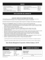
EngineOil Type:
EngineOil Capacity:
FuelCapacity:
SAE5W-30
37 ounces
Approx.5 Quarts
SparkPlug:
SparkPlug Gap:
F6RTC(951-10292)
.020"to .030"
Corporation,
Hoffman
Estates,
IL 60179
Model Number.................................................................
Serial Number .................................................................
Date of Purchase .............................................................
Recordthe modelnumber,serialnumber
and dateof purchaseabove
© Sears Brands,LLC
2
This machinewas builtto be operatedaccordingto the safeoperation practicesin this manual.As with anytype of powerequipment,
carelessnessor error on the partof the operatorcan resultin serious
injury.This machineis capableof amputatingfingers,hands,toes
and feet and throwingdebris.Failureto observethe followingsafety
instructionscouldresultin seriousinjuryor death.
This symbolpointsout importantsafetyinstructionswhich,if not
followed,couldendangerthepersonalsafetyand/orpropertyof
yourselfand others. Readand followall instructionsin this manual
beforeattemptingto operatethis machine.Failureto complywith
these instructionsmay resultin personalinjury.Whenyou seethis
symbol,HEEDITS WARNING!
CALIFORNIA
PROPOSITION
65
Your Responsibility--Restrict the use of this powermachineto
personswho read,understandand follow thewarningsand instructions in this manualand on the machine,
EngineExhaust,someof its constituents,and certainvehicle
componentscontainor emit chemicalsknownto Stateof California
to cause cancerand birthdefects or otherreproductiveharm,
SAVE THESE INSTRUCTIONS!
TRAiNiNG
PREPARATION
•
Thoroughlyinspectthearea wherethe equipmentisto be used.
Removeall doormats,newspapers,sleds,boards,wires and other
foreignobjects,whichcouldbe trippedoveror thrownby the auger/
impeller.
•
Alwayswear safetyglassesor eyeshieldsduringoperationand
while performingan adjustmentor repairto protectyoureyes.
Thrownobjectswhich ricochetcancause seriousinjuryto the
eyes.
Donot operatewithoutwearingadequatewinteroutergarments.
Donot wearjewelry,long scarvesor otherlooseclothing,which
could becomeentangledin movingparts.Wearfootwearwhich
will improvefooting on slipperysurfaces.
Usea groundedthree-wireextensioncordand receptaclefor all
machineswith electricstartengines.
•
•
Read,understand,and followall instructions
on the machineand
in themanual(s)beforeattemptingto assembleand operate.
Failureto do socan resultin serious injuryto the operatorand/
or bystanders.Keepthis manualin a safe placeforfuture and
regularreferenceand for orderingreplacementparts.
Be familiarwith all controlsand their properoperation.Knowhow
to stop the machineand disengagethemquickly.
Neverallowchildrenunder 14 yearsof age to operatethis
machine.Children14and over shouldreadand understandthe
instructionsand safe operationpracticesin this manualand on
the machineand be trainedand supervisedby an adult.
Neverallowadultsto operatethis machinewithoutproper
instruction.
•
•
Thrownobjectscan causeseriouspersonalinjury. Planyour
snow-throwingpatternto avoiddischargeof materialtoward
roads,bystandersand the like.
Keepbystanders,pets and childrenat least75 feet from the
machinewhile it is in operation.Stopmachineif anyoneenters
the area.
Disengageall controlleversbeforestartingthe engine.
Adjust collectorhousingheightto cleargravelor crushedrock
surfaces.
•
Exercisecautionto avoidslippingor falling,especiallywhen
operatingin reverse.
3
Neverattemptto make anyadjustmentswhileengineis running,
exceptwherespecificallyrecommendedin the operator'smanual.
Letengineand machineadjustto outdoortemperaturebefore
startingto clearsnow.
Safe Handling of Gasoline
Toavoidpersonalinjuryor propertydamageuseextremecare in
handlinggasoline.Gasolineis extremelyflammableand the vaporsare
explosive.Seriouspersonalinjurycan occurwhengasolineis spilled
on yourselfor yourclotheswhichcan ignite. Washyour skin and
changeclothesimmediately.
•
•
•
Neverremovegas capor add fuel whilethe engineis hot or
running.
•
•
Allowengineto coolat leasttwo minutesbeforerefueling.
Neveroverfill fueltank. Fill tankto no morethan1/2inchbelow
bottomof filler neck to providespace forfuel expansion.
Replacegasolinecapand tighten securely.
Exerciseextremecautionwhenoperatingon or crossinggravel
surfaces.Stay alertfor hidden hazardsor traffic.
Exercisecautionwhenchangingdirectionand whileoperatingon
slopes.Do notoperateon steep slopes.
Planyoursnow-throwingpatternto avoiddischargetowards
windows,walls,cars etc. Thus,avoidingpossibleproperty
damageor personalinjurycausedby a ricochet.
Neverdirect dischargeat children,bystandersand petsor allow
anyonein front of the machine.
Use onlyan approvedgasolinecontainer.
Extinguishall cigarettes,cigars,pipesand other sourcesof
ignition.
Neverfuel machineindoors.
•
•
•
Donot overloadmachinecapacityby attemptingto clearsnowat
too fastof a rate.
Neveroperatethis machinewithoutgoodvisibility or light. Always
be sureof yourfootingand keepa firm hold on the handles.Walk,
neverrun.
Disengagepowerto theauger/impellerwhentransportingor not
in use.
If gasolineis spilled,wipe it off theengineand equipment.Move
machineto anotherarea.Wait5 minutesbeforestartingthe
engine.
Neverstorethe machineor fuel containerinsidewherethereis an
openflame,spark or pilotlight(e.g. furnace,waterheater,space
heater,clothesdryeretc.).
Neveroperatemachineat high transportspeedson slippery
surfaces.Lookdownand behindand usecare whenbackingup.
If the machineshouldstart to vibrateabnormally,stop the engine,
disconnectthe spark plugwire and groundit againstthe engine.
Inspectthoroughlyfor damage.Repairanydamagebefore
startingand operating.
•
•
Allowmachineto cool at least 5 minutesbeforestoring.
Neverfill containersinsidea vehicleor on a truckor trailerbed
with a plasticliner.Alwaysplacecontainerson the groundaway
fromyour vehiclebeforefilling.
•
If possible,removegas-poweredequipmentfrom the truckor
trailerand refuelit on the ground.If this is not possible,then refuel
such equipmenton a trailerwith a portablecontainer,ratherthan
froma gasolinedispensernozzle.
Keepthe nozzlein contactwith the rimof the fuel tank or
containeropeningat all times untilfuelingis complete.Do not use
a nozzlelock-opendevice.
Disengageall controlleversand stop enginebeforeyouleave
the operatingposition(behindthe handles).Wait untilthe auger/
impellercomesto a completestop beforeuncloggingthechute
assembly,makingany adjustments,or inspections.
Neverput yourhand in the dischargeor collectoropenings.Do
not unclogchuteassemblywhileengineis running.Shutoff
engineand remainbehindhandlesuntilall movingparts have
stoppedbeforeunclogging.
•
•
•
Useonly attachmentsand accessoriesapprovedby the manufacturer (e.g.wheelweights,tire chains,cabsetc.). Forinformation
concerningthese items,call 1-800-469-4663.
Whenstartingengine,pull cord slowlyuntilresistanceis felt, then
pull rapidly.Rapidretractionof startercord(kickback)will pull
hand and armtowardenginefasterthan youcan let go. Broken
bones,fractures,bruisesor sprainscould result.
If situationsoccur whichare notcoveredin this manual,use care
and good judgment.
Toorder parts or scheduleservicefor this product,call 1-800469-4663.
OPERATION
•
Do not puthandsor feet near rotatingparts,in the auger/impeller
housingor chuteassembly.Contactwith the rotatingpartscan
amputatehandsand feet.
•
Theauger/impellercontrol leveris a safetydevice.Neverbypass
its operation.Doingso makesthe machineunsafeand may cause
personalinjury.
Thecontrol leversmustoperateeasilyin bothdirectionsand
automaticallyreturnto the disengagedpositionwhenreleased.
•
•
•
•
•
CLEARING
A CLOGGED
DISCHARGE
CHUTE
Handcontactwith the rotatingimpellerinsidethe dischargechute
is the mostcommoncauseof injuryassociatedwith snowthrowers.
Neveruse yourhand to cleanout thedischargechute.
Toclear thechute:
Neveroperatewith a missingor damagedchuteassembly.Keep
all safetydevicesin placeand working.
Neverrun an engine indoorsor in a poorlyventilatedarea. Engine
exhaustcontainscarbonmonoxide,an odorlessand deadlygas.
Do notoperatemachinewhileunder the influenceof alcoholor
drugs.
Mufflerand engine becomehotand can causea burn.Do not
touch.Keepchildrenaway.
1.
SHUTTHE ENGINEOFF!
2.
Wait 10secondsto be surethe impellerbladeshavestopped
rotating.
Alwaysusea clean-outtool, not yourhands.
3.
4
MAINTENANCE
& STORAGE
•
Nevertamperwith safetydevices.Checktheirproperoperation
regularly.Referto the maintenanceand adjustmentsectionsof
this manual.
•
Beforecleaning,repairing,or inspectingmachinedisengageall
controlleversand stop the engine.Wait untilthe auger/impeller
cometo a completestop.Disconnectthe sparkplug wireand
groundagainsttheengine to preventunintendedstarting.
Checkboltsand screwsfor propertightnessat frequentintervals
to keepthe machinein safe workingcondition.Also, visually
inspectmachinefor anydamage.
Do notchangetheengine governorsettingor over-speedthe
engine.Thegovernorcontrolsthe maximumsafeoperatingspeed
of the engine.
Snowthrowershaveplatesand skid shoesare subjectto wear
and damage.Foryoursafetyprotection,frequentlycheckall
componentsand replacewith originalequipmentmanufacturer's
(OEM)parts onlyas listed in the Partspagesof this operator's
manual.Useof parts which do not meetthe originalequipment
specificationsmay leadto improperperformanceand compromise safety!
Checkcontrolleversperiodicallyto verifythey engageand disengage properlyand adjust,if necessary.Referto the adjustment
sectioninthis operator'smanualfor instructions.
Maintainor replacesafetyand instruction
labels,as necessary.
Observeproperdisposallawsand regulationsfor gas, oil,etc. to
protectthe environment.
Priorto storing,run machinea few minutestoclear snowfrom
machineand preventfreezeup of auger/impeller.
Neverstorethe machineor fuel containerinsidewherethereisan
open flame,spark or pilot lightsuch as a waterheater,furnace,
clothesdryer etc.
Alwaysreferto the operator'smanualfor properinstructions
on
off-seasonstorage.
Checkfuelline,tank, cap,and fittings frequentlyfor cracksor
leaks.Replaceif necessary.
Do notcrank enginewith spark plug removed.
Accordingto the ConsumerProductsSafetyCommission(CPSC)
and the U.S.EnvironmentalProtectionAgency(EPA),this product
hasan AverageUsefulLifeof seven(7) years,or 60 hoursof
operation.At the end of theAverageUsefulLifehavethe machine
inspectedannuallybyan authorizedservicedealer to ensurethat
all mechanicaland safetysystemsare workingproperlyand not
wornexcessively.Failureto do so can resultin accidents,injuries
or death.
DO NOT MODIFY
ENGINE
Toavoidseriousinjuryor death,do not modifyengine in any way.
Tamperingwith the governorsettingcanlead to a runawayengineand
cause it to operateat unsafespeeds.Nevertamperwithfactory setting
of engine governor.
NOTICE
REGARDING
EMiSSiONS
Engineswhich are certifiedtocomplywith Californiaand federal
EPAemissionregulationsfor SORE(SmallOff RoadEquipment)are
certifiedto operateon regularunleadedgasoline,and mayinclude
the followingemissioncontrol systems:EngineModification(EM),
OxidizingCatalyst(OC), SecondaryAir Injection(SAI)and ThreeWay
Catalyst(TWO)if so equipped.
SPARK
ARRESTOR
This machineisequippedwith an internalcombustionengineand
shouldnotbe usedon or nearany unimprovedforest-covered,
brush-coveredor grass-coveredland unlessthe engine'sexhaust
systemisequippedwith a sparkarrestormeetingapplicablelocalor
statelaws (if any)
If a sparkarrestoris used, it shouldbe maintainedin effectiveworking
order by theoperator.Inthe State of Californiathe aboveis required
bylaw (Section4442 of the CaliforniaPublicResourcesCode). Other
statesmayhavesimilarlaws. Federallawsapplyon federallands.
A spark arrestorfor the muffleris availablethroughyournearestSears
Partsand RepairServiceCenter.
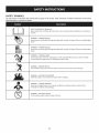
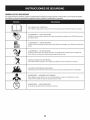
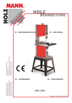
SAFETY
SYMBOLS
This pagedepictsand describessafetysymbolsthat mayappear on this product. Read,understand,and followall instructionson the machine
beforeattemptingto assembleand operate.
.i
+
i
READ THE OPERATOR'S MANUAL(S)
Read, understand,
and follow
all instructions
in the manual(s) before
attempting
to assemble
and
operate
WARNING--
ROTATING BLADES
Keep hands out of inlet and discharge openings
inside
WARNING--
machine is running. There are rotating
blades
while
machine is running. There are rotating
blades
ROTATING BLADES
Keep hands out of inlet and discharge openings
inside
WARNING--
ROTATING AUGER
Do not put hands or feet near rotating
Contact
while
with the rotating
parts, in the auger/impeller
parts can amputate
housing
or chute assembly.
hands and feet.
"JIp
WARNING--THROWN
This machine
OBJECTS
may pick up and throw objects
WARNING--GASOLINE
WARNING--
injury.
before refueling.
CARBON MONOXIDE
Never run an engine indoors
monoxide,
can cause serious personal
IS FLAMMABLE
Allow the engine to cool at least two minutes
WARNING--
which
or in a poorly ventilated
an odorless and deadly gas+
ELECTRICAL SHOCK
Do not use the engine's
electric starter in the rain
6
area. Engine exhaust contains carbon
Thispageleftintentionally
blank.
7
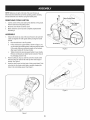
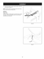
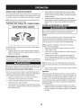
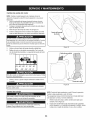
NOTE:Referencesto rightor left sideof the snowthrowerare
determinedfrom behindthe unit in the operatingposition(standing
directlybehindthe snow thrower,facingthe handlepanel).
t
Chute Control Head
REMOVING
1.
2.
3.
FROM CARTON
Cut the cornersof thecarton and lay the sidesflat on the ground.
Removeand discard all packinginserts.
Movethe snowthrowerout of thecarton.
Makecertainthe carton has beencompletelyemptiedbefore
discardingit.
ASSEMBLY
1.
Observethe lowerreararea of the snowthrowerto be sure both
cablesare alignedwith rollerguidesbeforepivotingthe handle
upward.
a. Placethe shiftleverin the F6position.
b.
c.
2.
3.
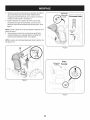
Chute
Pull up and back on upperhandleas shownin Figure1.As
youare raisingthe handleupward,make surethat bothends
of the centercableare positionedproperlyin the brackets.
Align upperhandlewith the lowerhandle.
Tightenhandknobs securingupper handleto lowerhandle.
Removeand discard any rubberbands,if present.Theyare
for packagingpurposesonly.
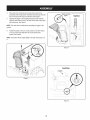
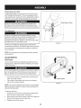
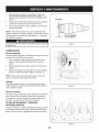
Figure2
f
Removecotter pin,wingnut, and hexscrewfromchute control
headand clevis pin and bow-tiecotterpin from chutesupport
bracket.See Figure2.
Insertthe chutecontrol rod intoinputof chute controlhead.Push
rod as far intothe chute controlheadas possible,keepingthe
holesin the rod pointingupward.See Figure3.
\
/
Figure3
Figure1
8
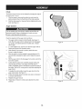
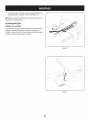
4.
5.
Placechuteontochute baseand ensurechute control rodis
positionedunderhandle panel.Installhex boltpreviouslyremoved
but do not securewith wingnut at this time.See Figure4.
Squeezethe triggeron thehandle paneljoystickand rotatethe
chuteby hand to face forward.Theholes in the chutecontrol input
will be facing up.See Figure5.
f
Chute Controlf
NOTE:The chutewill not rotatewithoutsqueezingthe triggeron the
joystick.
6.
Rotatethejoystickto the one o'clockpositionsothe silver indicator arrowon the inputshaftbelowthe controlpanel points
upward.See Figure6.
NOTE:Thejoystickwillbe angledslightlyto the right.See Figures5 &
6.
Figure5
f
FroatView
Joystick
Figure4
J
Figure6
9
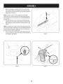
.
Makesureall cables are routedto the left of the chutecontrol
rod.Line up the hole in the rod with thearrowon the inputshaft
and insertthe end of the rod into the inputshaftbelowjoystickon
handlepanel.See Figure7.
/i _
NOTE:Thechute controlrod will fit snugglyintothe inputshaft.
Supportthe rear of thedash panelwith one handwhileinsertingthe
rod with yourotherhandto ensurethe rod is insertedell the way into
the input shaft.
8. Nowpushthe chutecontrol rod back towardsthe handlepanel
untilthe hole in the rodlines up with the hole in the chute control
inputclosestto the chutecontrolhead. Insertthe cotterpin. See
Figure8.
NOTE:The secondholeis usedto achievefurther engagementof the
rod intothe inputshaft if requiredand can be usedlaterfor adjustment
if the chutedoes notfully rotate.Referto the Service& Maintenance
sectionfor ChuteControlRodadjustments.
9. Finishsecuringchute controlheadto chutesupportbracketwith
wing nut, and clevispin and bow-tiecotterpin removedearlier.Do
notovertighten.See Figure9.
/
/
.J
Figure8
/
/
' .....................................................
i_"i
}
Figure7
Figure9
10
/
10. Checkthatall cablesare properlyroutedthroughthecable guide
on the engine.See Figure10.
"_
/
NOTE:If the chute controlis not assembledcorrectlyit will not move
freelynor will it movefully to the rightand left.
SET-UP
Shear
Pins
Holesare locatedin the handlepanelfor convenientshearpin storage.
See Figure11.Referto the Operationsectionfor moreinformation
regardingshearpin replacement.
Figure10
f
J
Figure11
11
Chute
Clean=Out
Tool
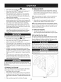
A chute clean-out tool is fastenedto the top of the augerhousing
with a mountingclip. See Figure12.The tool is designedto cleara
chuteassemblyof ice and snow.This item is fastenedwith a cabletie
at the factory.Cut thecable tie beforeoperatingthe snowthrower.
Chutedean=out Tool
loft _1
.allmovingpartshave
stoppedbeforeusingthe clean-outtool to clearthe chuteassembly.
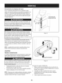
Tire Pressure
Underanycircumstancedo notexceed manufacturer'srecommendedpsi. Equaltire pressureshouldbe maintainedat all times.
Excessivepressurewhenseatingbeadsmaycausetire/rim
assemblyto burst with force sufficientto causeseriousinjury. Refer
to sidewallof tirefor recommendedpressure.
Figure12
Thetires are over-inflatedfor shippingpurposes.Checkthetire
pressurebeforeoperatingthe snow thrower.Referto the tire sidewall
for tiremanufacturer'srecommendedpsiand deflate(or inflate)the
tires as necessary.
NOTE:Equaltire pressureis to be maintainedat all timesfor performancepurposes.
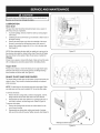
ADJUSTMENTS
Smooth
Surface
Uneven
Surface
Skid Shoes
The snowthrowerskid shoesare adjustedupwardat thefactory for
shippingpurposes.Adjustthemdownward,if desired,priorto operating the snowthrower.
It is not recommendedthat youoperatethis snowthroweron gravel
as it can easilypick up and throwloosegravel,causingpersonal
njuryor damageto the snowthrowerand surroundng property.
•
•
Forclose snow removalon a smoothsurface,raiseskid shoes
higheron the auger housing.
Use a middleor lowerpositionwhenthearea to be clearedis
uneven,such as a graveldriveway
Figure13
NOTE:If youchooseto operatethe snowthroweron a gravelsurface,
keepthe skid shoesin positionfor maximumclearancebetweenthe
groundand the shaveplate.
Toadjustthe skid shoes:
1.
2.
3.
Loosenthe four hexnuts (two on each side)and carriagebolts.
Moveskid shoesto desiredposition.See Figure13.
Makecertainthe entirebottomsurfaceof skid shoeis againstthe
groundto avoidunevenwearon the skid shoes.
Retightennuts and boltssecurely.
12
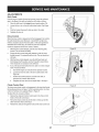
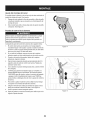
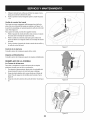
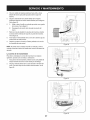
Chute
f
"_
Thedistancesnowis throwncan be adjustedby changingthe angle of
the upperchute.Todo so:
1.
2.
Stopthe engineby removingthe ignitionkeyand loosenthe
plasticwingknobfoundon the left sideof the chuteassembly.
Pivotthe chute upwardor downwardbeforeretighteningthewing
knob.See Figure14.
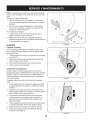
Auger Control
Priorto operatingyoursnowthrower,carefullyread and followall
instructionsbelow.Performall adjustmentsto verifyyoursnow
throweris operatingsafelyand properly.
Checktheadjustmentof the augercontrolas follows:
1.
2.
3.
4.
Theaugercontrol is locatedon the left handle.See Figure15
inset.Whentheauger controlis releasedand in the disengaged
"up"position,the cableshouldhavevery little slack. It should
NOT be tight.
In a well-ventibtedarea,start the snowthrowerengine.Referto
Startingthe Enginein the Operationsection.
Whilestandingin the operator'sposition(behindthe snow
thrower),engagethe augers.
Allowtheaugersto remainengagedfor approximatelyten (10)
secondsbeforereleasingthe augercontrol.Repeatthis several
times.
5.
With theauger controlin thedisengaged"up" position,walkto the
front of the machine.
6.
Confirmthat the augershavecompletelystoppedrotatingand
show NOsignsof motion.If anyauger showsANY signof
rotating,immediatelyreturnto the operator'spositionand shutoff
the engine.Waitfor ALL movingparts to stop beforeadjustingthe
augercontrol.
Toreadjustthecontrolcable, loosentheupper hexbolt on the
augercablebracket.See Figure15.
7.
8.
9.
Figure14
\\
\
\
\
Positionthe bracketupwardto providemoreslack(or downward
to increasecabletension).
Retightenthe upperhex bolt.
10. Repeatsteps2-6 aboveto verifyproperadjustmenthasbeen
achieved.
J
Figure15
13
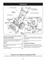
f
Shift Lever
Drive Control
/
/
Two=WayChuteControl" (Joystick)
J
Auger Control
Headlight.
Gas Cap
\
Wheel Steering Control
ChuteAssembly
\\
Recoil Starter
Oil Fill
Handle
Muffler
\
Clean Out
Tool
\
FUEL LEVEL
)riffler
Auger
Hous_
\
Choke
Control
Throttle
Electric
Starter
Control
Button
/
Augers
Oil Drain
Skid Shoe
Electric Starter Outlet
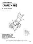
Figure16
Nowthat youhaveset up yoursnowthrower,it'simportantto become
acquaintedwith its controlsand features.Referto Figure16.
SHIFT
LEVER
The shiftleverislocatedon the rightsideof the handle panel.
Placethe shiftleverinto anyof eightpositionsto controlthe
directionof travel and groundspeed.
Forward
NOTE: Donot turnthe key in an attemptto startthe engine.Doingso
may causeit to break,
6
CHOKE
5
The chokecontrolisfoundon the rearof the engineand isactivated
4
by turningthe rotarychoke knobto the CHOKEposition.Activating
the chokecontrolclosesthe choke plateon thecarburetorand aids in
startingthe engine,
3
Yoursnowthrowerhas six forward(F) speeds.Positionone (1)is t 2
the slowestand positionsix (6) is the fastest.
F1
Reverse
Yoursnowthrowerhastwo reverse(R) speeds.One (1) is the
slowerand two (2) is the faster.
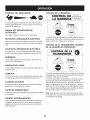
CONTROL
PRIMER
Depressingthe primerforcesfueldirectlyintothe engine'scarburetor
to aid incold-weatherstarting.
OIL FILL
KEY
Engineoil levelcan be checkedand oil added throughthe oil fill.
The keyisa safety device.It mustbe fully insertedin orderfor the
engineto start. Removethe keywhenthe snowthroweris notin use.
GAS CAP
Unthreadthe gas capto add gasolineto thefuel tank.
Meets ANSi Safety Standards
CraftsmanSnowThrowersconformto the safetystandardof the AmericanNationalStandardsInstitute(ANSI).
14
THROTTLE CONTROL
The augercontrol is locatedon the left handle.Squeezethe control
grip againstthe handleto engagethe augerand startsnowthrowing
action.Releaseto stop.
DRIVE CONTROL/AUGER
Thethrottlecontrolis locatedon the rearof the engine.It regulatesthe
speedof theengine and will shutoff the enginewhenmovedintothe
STOPposition.
RECOIL
STARTER
CONTROL
LOCK
DRIVE
CONTROL
HANDLE
This handleis usedto manuallystartthe engine.
ELECTRIC
STARTER
BUTTON
Pressingthe electricstarterbuttonengagesthe engine'selectric
starterwhenpluggedintoa 120Vpowersource.
ELECTRIC
STARTER
OUTLET
The drivecontrolis locatedon the righthandle.Squeezethe control
grip againstthe handleto engagethe wheeldrive. Releaseto stop.
Requiresthe useof a three-prongoutdoorextensioncordand a 120V
powersource/walloutlet.
The drivecontrolalso lockstheauger controlso youcan operate
the chute directionalcontrolwithoutinterruptingthe snowthrowing
process.If the augercontrolis engagedsimultaneouslywith the drive
control,the operatorcan releasethe augercontrol (on the left handle)
and the augerswill remainengaged.Releaseboth controlsto stop the
augersand wheeldrive.
AUGERS
Whenengaged,the auger bladesrotateand drawsnowintothe auger
housing.
SKID SHOES
NOTE:Alwaysreleasethedrivecontrol beforechangingspeeds.
Failureto do so will result in increasedwearon yourmachine'sdrive
system.
Positionthe skid shoesbasedon surfaceconditions.Adjust upward
for hard-packedsnow.Adjust downwardwhenoperatingon gravelor
crushedrock surfaces.
TWO-WAY
CHUTE
ASSEMBLY
STEERING
CONTROL
CHUTIE DiRECTiONAL
Snowdrawninto theauger housingis dischargedout the chute
assembly.
WHEEL
CHUTE
f.
CONTROL
CONTROLS
Theleft and rightwheelsteeringcontrolsare locatedon theunderside
of the handles.Squeezethe rightcontrolto turn right; squeezethe left
controlto turn left.
CHUTEROTATE
LEFT
NOTE:Operatethe snowthrowerin open areasuntilyou are familiar
with thesecontrols.
\
AUGER CONTROL
CHUTEROTATE
RIGHT
J
The two-waychute control(Joystick)is locatedon the left side of the
handlepanel.
*
15
Tochangethe directionin which snowis thrown,squeezethe
buttonon the chutecontrol leverand pivotthe chutecontrol lever
to the rightor to the left.
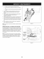
CLEAN-OUT TOOL
•
•
Neveruseyourhandsto cleara cloggedchuteassembly.Shut
loft engineand remainbehindhandlesuntil all movingparts have
lstopped beforeusingtheclean-outtool to clearthe chuteassembly.
•
Thechute clean-outtool is convenientlyfastenedto the rear of the
augerhousingwith a mountingclip. Shouldsnowand ice become
lodgedin thechute assemblyduringoperation,proceedas followsto
safelycleanthechute assemblyand chute opening:
1. Releaseboththe AugerControland the DriveControl.
2.
3.
4.
5.
6.
)or.
Useextremecarewhen handlinggasoline.Gasolineis extremely
flammableand thevaporsare explosive.Never fuelthe machine
indoorsor whilethe engine is hotor running.Extinguishcigarettes,
cigars,pipesand othersourcesof ignition.
rear of the augerhousing.
Use the shovel-shapedend of theclean-outtool to dislodgeand
scoopany snowand icewhich hasformedin and near thechute
assembly.
1.
2.
Refastenthe clean-outtool to the mountingclip on the rear of
theauger housing,reinsertthe ignitionkey and startthe snow
thrower'sengine.
Whilestandingin the operator'sposition(behindthesnow
thrower),engagethe auger controlfora few secondsto clear any
remainingsnowand ice from thechute assembly.
STARTING
Be carefulnotto spillfuel whenrefueling.Spilledfuel or fuel vapor
may ignite,ifany fuelis spilled,makesurethe area isdry before
startingthe engine.
Avoidrepeatedor prolongedcontact with skinor breathingof
•
Stopthe engineby removingthe ignitionkey.
Removethe clean-outtoolfrom the clip whichsecuresit to the
BEFORE
Refuelin a well-ventilatedarea with the enginestopped.Do not
smokeor allowflamesor sparksin the areawherethe engineis
refueledor wheregasolineisstored.
Donot overfillthe fueltank.After refueling,makesurethe tank
cap is closed properlyand securely.
STARTING
THE ENGINE
Alwayskeep handsand feet clearof movingparts. Donot usea
pressurizedstartingfluid.Vaporsare flammable.
ENGINE
NOTE:Allowthe engineto warm up for a few minutesafter starting.
The enginewill notdevelopfull poweruntilit reachesoperating
temperatures.
Read,understand,and followall instructionsand warningson the
machineand in this manualbeforeoperating.
1.
Makecertainboththe augercontrol and drivecontrolare in the
disengaged(released)position.
2.
insert keyinto slot. Makesureit snaps intoplace. Donot attempt
to turn the key.
Oil
The unit was shippedwith oil in the engine.Checkoil levelbefore
eachoperationto ensureadequateoil inthe engine.Forfurther
instructions,refertothe stepson page 18.
NOTE: Theenginecannot startwithoutthe keyfully insertedintothe
ignitionswitch.
NOTE:Be sureto checkthe engineon a levelsurfacewith the engine
stopped.
1. Removethe oil fillercap/dipstickand wipethe dipstickclean.
2. insertthe cap/dipstickintothe oil filler neck,butdo NOTscrewit
in.
3.
Cleanaroundfuel fill beforeremovingcap to fuel.
A fuel levelindicatoris locatedin the fueltank. See Figure15
inset. Be carefulnotto overfill.Filltank untilfuel reachesthe fuel
level indicatorto allowspacefor fuel expansion.
Electric
Removethe oil fillercap/dipstick,ifthe levelislow,slowlyadd
oil (5%30, with a minimumclassificationof SF/SG)untiloil level
registersbetweenhigh (H) and low(L).
NOTE:Do notoverfill.Overfillingwith oil mayresult inenginesmoking,
hard startingor spark plugfouling.
4. Replaceand tighten cap/dipstickfirmlybeforestartingengine.
Gasoline
Use automotivegasoline(unleadedor low leadedto minimizecombustionchamberdeposits)with a minimumof 87 octane.Gasolinewith
up to 10%ethanolor 15%MTBE(MethylTertiaryButyl Ether)canbe
used. Neverusean oil/gasolinemixtureor dirty gasoline.Avoidgetting
dirt, dust,or waterin thefuel tank. DO NOTuse E85gasoline.
16
Starter
The optionalelectricstarteris equippedwith a groundedthree-wire
powercordand plug,and is designedto operateon 120volt AC
householdcurrent.It mustbe usedwith a properlygroundedthreeprong receptacleat all timesto avoidthe possibilityof electricshock.
Followall instructionscarefullyprior to operatingtheelectricstarter.
DONOTuse electricstarterin the rain.
Determinethat yourhome'swiringis a three-wiregroundedsystem.
Ask a licensedelectricianif you are notcertain.
If you havea groundedthree-prongreceptacle,proceedas follows.
If you do not havethe properhousewiring, DONOT usethe electric
starterunder anyconditions.
1. Plugthe extensioncord intothe outlet locatedon the engine's
surface.Plug the otherend of extensioncord intoa three-prong
120-volt,grounded,AC outlet in a well-ventilatedarea.
2.
Movethrottlecontrolto FAST(rabbit)'_
3.
Movechoketo the CHOKE I,'_1 position(coldenginestart). If
engineis warm,placechokein RUNposition.
4.
Pushprimerthree (3) times, makingsureto covervent hole in
primerbulbwhen pushing.If engineis warm,pushprimeronly
once.Alwayscover venthole whenpushing.Coolweathermay
requireprimingto be repeated.
Pushstarterbuttonto start engine.Oncethe enginestarts,immediatelyreleasestarterbutton.Electricstarteris equippedwith
thermaloverloadprotection;systemwill temporarilyshut-downto
allowstarterto cool if electricstarterbecomesoverloaded.
5.
6.
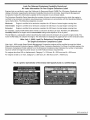
TO ENGAGE
position.
With the throttlecontrolin the Fast(rabbit) position,moveshift
leverinto one of the six forward(F) positionsor two reverse(R)
positions.Selecta speedappropriatefor the snowconditionsand
a paceyou'recomfortablewith.
NOTE: When selectinga DriveSpeed,use the slowerspeedsuntil
you are comfortableand familiarwiththe operationof the snow
thrower.
2. Squeezethe drivecontrolagainstthe handleand the snow
throwerwill move.Releaseit and drive motionwill stop.
NOTE:NEVERrepositionthe shiftlever(changespeedsor direction
of travel)withoutfirst releasingthe drivecontrol and bringingthe snow
throwerto a completestop.Doingsowill resultin prematurewearto
the snow thrower'sdrivesystem.
As theenginewarms,slowlyrotatethe chokecontrol to RUN
position.If the enginefalters,restartengineand run with choke
at half-chokepositionfor a short periodof time,and then slowly
rotatethe chokeinto RUNposition.
7.
After engineis running,disconnectpowercordfrom electric
starter.Whendisconnecting,alwaysunplugthe end at the wall
outletbeforeunpluggingtheoppositeend from the engine.
Recoil Starter
TO ENGAGE
1.
Movethrottlecontrolto FAST(rabbit)_J_ position.
2.
Movechoketo the CHOKE I_¢1 position(coldenginestart). If
engineis warm,placechokein RUNposition.
Pushprimerthree (3) times, makingsureto covervent hole when
pushing.If engine iswarm,push primeronlyonce. Alwayscover
vent holewhen pushing.Coolweathermay requireprimingto be
repeated.
3.
4.
5.
AUGERS
Toengagethe augersand startthrowingsnow,squeezethe
auger controlagainstthe left handle.Releaseto stop theaugers.
REPLACING
Do notpull the starterhandlewhilethe engine running.
1.
DRIVE
SHEAR
PINS
The augersare securedto the spiralshaftwith shearpins and cotter
pins.If the augersshouldstrikea foreignobject or ice jam, the snow
throweris designedso that the pins mayshear.If theaugerswill not
turn, checkto see if the pins havesheared.See Figure17.
NEVERreplacethe augershearpinswith anythingotherthan Sears
SKU#88389/0EM PartNo. 738-04124Areplacementshearpins.
Anydamageto theauger gearboxor other componentsas a resultof
failingto do sowill NOTbe coveredbyyour snowthrower'swarranty.
Pull gentlyon the starterhandleuntil it beginsto resist,then
pull quicklyand forcefullyto overcomethe compression.Engine
shouldstart. Donot releasethe handleand allow it to snapback.
Returnrope SLOWLYto originalposition.If required,repeatthis
step.
As theenginewarms,slowlyrotatethe chokecontrol to RUN
position.If the enginefalters,restartengineand run with choke
at half-chokepositionfor a short periodof time,and then slowly
rotatethe chokeinto RUNposition.
Alwaysturn off thesnow thrower'sengineand removethe key priorto
replacingshearpins.
f
-,
To avoidunsupervisedengineoperation,neverleavethe machine
unattendedwith the engine running.Turnthe engineoff after use and
removekey.
STOPPING
THE ENGINE
/
After youhavefinishedsnow-throwing,run enginefora few minutes
beforestoppingto help dry off any moistureon the engine.
1. Movethrottlecontrolto OFF position.
2.
3.
Removethekey.Removingthe key will reducethe possibilityof
unauthorizedstartingof the enginewhileequipmentis notin use.
Keepthe key in a safe place.The enginecannotstart withoutthe
key.
Wipeany moistureawayfrom the controlson theengine.
Figure17
17
MAINTENANCE
Beforeperforminganytype ofmaintenance/service,
disengageall
controlsand stoptheengine.Waituntilall movingpartshavecometo
a completestop.Disconnectsparkplugwireandgroundit againstthe
enginetopreventunintendedstarting.Alwayswearsafetyglassesduring
operationor whileperforminganyadjustmentsor repairs.
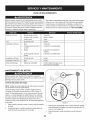
EachUseand every 5
hours
1st5 hours
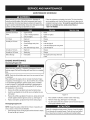
SCHEDULE
Followthe maintenanceschedulegiven below.This chart describes
serviceguidelinesonly. Usethe ServiceLog columnto keeptrackof
completedmaintenancetasks.To locate the nearest Sears Service
Centeror to scheduleservice,simplycontactSearsat
1-800-4-MY-HOME®.
1.
Check
Unit and engine.
2.
3.
Tightenor replace
Clean
1.
Engineoil
1.
Change
1.
2.
Engineoil level
Looseor missinghardware
3.
1.
Sparkplug
1.
Check
2.
3.
Controllinkagesand pivots
Wheels
2.
3.
Lubewith light oil
Lubewith multipurposeautogrease
4.
Gear shaftand Augershaft
4.
Lubewith light oil
Annuallyor 50 hours
1.
Engineoil
1.
Change
Annuallyor 100 hours
1.
Sparkplug
1.
Change
BeforeStorage
1.
Fuelsystem
1.
Runengineuntilit stopsfrom lack
d fuel
Annuallyor 25 hours
ENGINE
Checking
MAINTENANCE
Engine
Oil
Beforelubricating,repairing,or inspecting,disengageall controls
Iand stop engine.Wait untilall movingpartshavecometo a complete
_stop.
NOTE: Checktheoil levelbeforeeachuseto be surecorrectoil level
is maintained.
Whenaddingoil to the engine,referto viscositychart below.Engine
oil capacityis 1100ml (approx.37 oz.). Donot over-fill.Usea 4-stroke,
or an equivalenthighdetergent,premiumquality motoroil certified
to meet or exceedU.S.automobilemanufacturer'srequirementsfor
serviceclassificationSG, SR MotoroilsclassifiedSG, SFwill show
this designationon the container.
1. Removethe oil fillercap/dipstickand wipethe dipstickclean.
2.
3.
4.
Insertthe cap/dipstickintothe oil filler neck,and tightenthe cap
until seated.
J
Removethe oil fillercap/dipstick.If levelis low, slowlyadd oil until
oil levelregistersbetweenhigh (H) and low (L). See Figure18.
Replaceand tighten cap/dipstickfirmlybeforestartingengine.
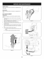
Changing
Engine
Oil
NOTE:Changethe engineoil after the first5 hoursof operationand
oncea seasonor every 50 hoursthereafter.
1. Drainfuelfrom tank by runningengineuntilthe fuel tank is empty.
Be surefuel fill cap is secure.
18
Figure18
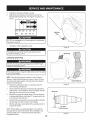
2.
3.
Placesuitableoil collectioncontainerunderoil drain plug.
Removeoil drain plug.See Figure19on nextpage.
4.
Tip unit to drainoil intothe container.Usedoil mustbe disposed
of at a propercollectioncenter.
Usedoil is a hazardouswasteproduct.Disposeof usedoil properly.
IDo notdiscardwith householdwaste.Checkwith your localauthorilties or SearsService Centerfor safe disposal/recyclingfacilities.
.
6.
Reinstallthe drain plugand tightenit securely.
Refillwith the recommendedoil and checkthe oil level.See
RecommendedOil Usagechart.Theengine'soil capacityis 37
ounces.
i
u
[
(%-40 °-20 o 0o 200 400
("c)
Oil Drain
Plug
-300 -200 -10° 0°
DO NOTuse nondetergentoil or 2-strokeengineoil. It could shorten
the engine'sservicelife.
7.
Reinstallthe oil fillercap/dipsticksecurely.
Figure19
Thoroughlywashyour handswith soap andwater as soonas
possibleafter handling usedoil.
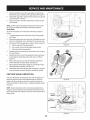
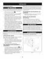
Checking
Spark
Spark Plug
Plug
O
DO NOTcheckfor sparkwith spark plug removed.DO NOTcrank
engine with sparkplug removed.
If the enginehas been running,the mufflerwill be very hot. Be careful
notto touch the muffler.
NOTE: Checkthe sparkplug oncea seasonor every 25 hoursof
operation.Changethe sparkplug oncea seasonor every 100hours.
Toensureproperengine operation,the sparkplug mustbe properly
gappedand freeof deposits.
1.
2.
3.
4.
5.
J
Figure20
Removethespark plug bootand use a sparkplug wrenchto
removethe plug.See Figure20.
Visuallyinspectthe spark plug.Discardthe spark plug if thereis
apparentwear,or if the insulatoris crackedor chipped.Cleanthe
sparkplug with a wirebrush if it is to be reused.
Electrode
Measurethe plug gap with a feelergauge.Correctas necessary
by bendingsideelectrode.See Figure21.The gap shouldbe set
to .02-.03inches(0.60-0.80ram).
Checkthatthe sparkplug washeris in good conditionand thread
the sparkplug in by handto preventcross-threading.
After thespark plug is seated,tightenwith a spark plugwrenchto
compressthe washer.
NOTE:Wheninstallinga newsparkplug,tighten 1/2-turnafter the
sparkplug seatsto compressthe washer.Whenreinstallinga used
sparkplug,tighten 1/8-to 1/4-turnafter the sparkplug seatsto
compressthe washer.
.02-.03 in.
{0.60-0.80 ram)
Figure21
19
hotandcan
ine.
LUBRICATION
O i
Gear Shaft
Thegear (hex)shaft shouldbe lubricatedat least oncea seasonor
afterevery 25 hoursof operation.
1. Topreventspillage,removeall fuel fromtank by runningengine
until it stops.
2.
3.
4.
Carefullypivotthe snowthrowerup and forwardso that it restson
theauger housing.
Removethe lowerframecover fromthe undersideof the snow
throwerby removingthe self-tappingscrewswhich secureit.
Applya lightcoatingof engineoil (or 3-in-1oil) to the hexshaft.
See Figure22.
)
X"
{;:7X
/ ....
"?X
)
7/' ................
Figure22
NOTE:Whenlubricatingthe hexshaft, be carefulnotto get any oil on
thealuminumdriveplateor rubberfrictionwheel. Doingsowill hinder
the snowthrower'sdrive system.Wipeoff anyexcessor spilledoil.
Wheels
At least oncea season,removebothwheels.Cleanand coat theaxles
with a multipurposeautomotivegreasebeforereinstallingwheels.
Auger Shaft
At least oncea season,removethe shearpinson augershaft. Spray
lubricantinsideshaft,and aroundthe spacersand flangebearings
foundat eitherend of the shaft. See Figure23.
SHAVE
PLATE AND SKID SHOES
The shaveplateand skid shoeson the bottomof the snowthrowerare
subjectto wear.They shouldbe checkedperiodicallyand replaced
whennecessary.
/
J
NOTE:Theskid shoeson this machinehavetwo wearedges.When
one sidewears out, theycan be rotated1800to usethe otheredge.
Figure23
f
To removeskid shoes:
1.
Removethe two carriagebolts,washers(if equipped),and hex
flangenutsthat secureeach skid shoeto the snowthrower.
2.
Reassemblenew skid shoeswith the fourcarriagebolts (two on
eachside), washers,and hex flangenuts.Referto Figure24.
To removeshaveplate:
1.
2.
Removethe carriageboltsand hexnuts whichattachit to the
snowthrowerhousing.
Reassemblenew shaveplate,makingsureheadsof carriage
bolts are to the insideof housing.Tightensecurely.See Figure24.
Figure24
2O
ADJUSTMENTS
Shift Cable
If thefull rangeof speeds(forwardand reverse)cannotbe achieved,
referto the figureto the rightand adjustthe shift cableas follows:
1. Placethe shiftleverin thefastest forward speedposition(F6).
2. Loosenthe hex nuton the shiftcable indexbracket.See Figure
25.
3.
4.
Pivotthe bracketdownwardto take up slack in the cable.
Retightenthehex nut.
Drive
Control
Whenthedrivecontrol is releasedand in thedisengaged"up"position,
the cableshouldhavevery little slack.It shouldNOTbe tight. Also,
if thereis excessiveslackin thedrive cableor if the unitexperiences
intermittentdrivewhileusing,the cable mayneed to be adjusted.
Checktheadjustmentof the drivecontrolas follows:
1. With thedrivecontrol released,pushthe snowthrowergently
forward.The unitshouldroll freely.
2.
3.
4.
J
f
Engagethe drivecontroland gently attemptto pushthe snow
throwerforward.Thewheelsshouldnotturn. The unitshouldnot
roll freely.
With thedrivecontrol released,movethe shift leverbackand
forth betweenthe R2positionand the F6 positionseveraltimes.
Thereshouldbe no resistancein the shiftlever.
If anyof the abovetests failed,the drivecable is in needof adjustment.Proceedas follows:
a.
b.
Shutoff theengineas instructedin the Operationsection.
Loosenthe lowerhexbolt on the drivecable bracket.See
Figure26.
c.
Positionthe bracketupwardto providemoreslack(or
downwardto increasecabletension).
Retightenthe lowerhex boltand repeatsteps1 through4.
d.
Chute
Control
.........
J
Rod
Figure26
Toachievemorechutecontrolrod engagementin the input shaftunder
the handlepanelshownin Figure7 in the Assemblysection,the chute
controlrod will haveto be adjusted.Referto Figure27.
Toadjustthis rod,proceedas follows:
1.
2.
3.
J
Removethecotterpin fromthe hole closestto the chute control
headon thechute controlinput.
Pull outthe chute controlrod untilthe holein it lines up with the
otherhole in the chute controlinput.
\
Reinsertthe cotterpin throughthis hole and thechute controlrod.
/
/
21
,
Figure27
\
Auger Control
Referto the Assemblysectionfor instructions
on adjustingtheauger
controlcable.
Skid Shoes
Referto the Assemblysectionfor instructions
on adjustingthe skid
shoes.
BELT REPLACEMENT
Auger Belt
To removeand replaceyoursnow thrower'sauger belt, proceedas
follows:
1.
Topreventspillage,removeall fuel fromtank by runningengine
until itstops.
2.
Removethe plasticbelt coveron the front of the engineby removingthe two self-tappingscrews.See Figure28.
Rollthe auger beltoff theengine pulley.See Figure29.
3.
4.
5.
6.
J
Figure29
Carefullypivotthe snowthrowerup and forwardso that itrestson
theauger housing.
Removethe frame coverfrom the undersideof the snow thrower
by removingthe self-tappingscrewswhich secureit. See Figure
30.
Removethe beltas follows.Referto Figure31.
A. Loosenand removethe shoulderscrewwhich actsas a belt
B.
keeper.
Unhookthe auger brakebracketspringfrom the frame.
f
J
Figure30
f
.....i
Figure28
_jz:.................
J
Figure31
22
7. Remove
thebeltfromaround
theauger
pulley,
andslipthebelt
between
thesupport
bracket
andtheauger
pulley.
SeeFigure
32.
8. Reassemble
auger
beltbyfollowing
these
instructions
inopposite
order
andmanner
ofremoval.
9. Perform
theAuger
Control
testoutlined
intheAssembly
section
ofthismanual.
iO
i
NOTE:
DoNOT
forget
toreinstall
theshoulder
screw
andreconnect
thespring
totheframe
afterinstalling
areplacement
auger
belt.
Drive Belt
Toremoveand replaceyoursnow thrower'sdrivebelt, proceedas
follows:
1.
Topreventspillage,removeall fuel fromtank by runningengine
untilit stops.
2.
Removetheplasticbelt coveron the front of the engineby removingthe two self-tappingscrews.See Figure28 on previouspage.
Removethebelt from enginepulleyas follows. Referto Figure33.
3.
A.
B.
4.
5.
6.
7.
8.
Figure32
Rollthe auger beltoff theengine pulley.
Use a wrenchto pivotthe idlerpulleytowardthe right.
C. Lift the drivebelt off engine pulley.
Carefullypivotthe snowthrowerup and forwardsothat itrestson
the augerhousing.
Removetheframe coverfrom the undersideof the snowthrower
by removingthe self-tappingscrewswhich secureit. Referto
Figure30.
///
Back outthe stop bolt to increasethe clearancebetweenthe
frictionwheeldisc and frictionwheel.See Figure34.
Slip the drivebelt off the frictionwheeldisc and betweenfriction
wheeland frictionwheeldisc.See Figure34.
Reassembledrive beltby followingthese instructions
in opposite
orderand mannerof removal.Be sureto reinstallthe stop bolt.
FRICTION
WHEEL
INSPECTION
If the snowthrowerfails to drivewith thedrivecontrolengaged,and
performingthe DriveControlCableAdjustmentfails to correctthe
problem,the frictionwheelmay needto be replaced.Examinethe
frictionwheelrubberfor signsof wearor crackingand replacewheelif
necessary.
.J
Figure33
f
NOTE:Severalcomponentsmustbe removedand specialtools are
requiredin order to replacethis snowthrower'sfrictionwheel. If your
frictionwheelneedsto be replaced,contactthe nearestSearsParts&
RepairCenter.
Frictio_
Friction
Wheel Disc
Stop
Figure34
23
If the snowthrowerwillnot be usedfor30 daysor longer,or if it is the end of the snowseasonwhenthe last possibilityof snowis gone,the
equipmentneedsto be storedproperly.Followstorageinstructionsbelowto ensuretop performancefrom the snowthrowerfor manymoreyears.
PREPARING
PREPARING
ENGINE
Whenstoringthe snowthrowerin an unventilatedor metal storage shed,careshouldbe taken to rustprooftheequipment.Using
a light oil or silicone,coat theequipment,especiallyanychains,
springs,bearingsand cables.
Enginesstoredover30 days need to be drainedof fuel to prevent
deteriorationand gumfrom formingin fuel systemor on essential
carburetorparts.If thegasolinein yourenginedeterioratesduring
storage,youmay needto havethe carburetor,and otherfuel system
components,servicedor replaced.
1.
2.
3.
Removeall fuel fromtank by runningengineuntil it stops. Donot
attemptto pourfuel from the engine.
Changethe engineoil.
Removesparkplug and pour approximately1 oz. (30 rnl) of clean
engineoil intothe cylinder.Pullthe recoilstarterseveraltimesto
distributetheoil, and reinstallthe spark plug.
4.
Cleandebrisfrom aroundengine,and under,around,and behind
muffler.Applya lightfilm of oil on anyareasthat are susceptible
to rust.
•
Storein a clean,dry and wellventilatedarea awayfrom anyappliancethat operateswith a flame or pilotlight, such as a furnace,
waterheater,or clothesdryer.Avoidany areawith a spark
producingelectricmotor,or wherepowertools are operated.
Neverstoresnow throwerwith fuel in tank indoorsor in poorlyventilatedareas,wherefuel fumesmay reachan openflame,spark or pilol
lightas on a furnace,water heater,clothesdryer or gas appliance.
•
•
SNOW THROWER
If possible,avoidstorageareaswith high humidity.
Keepthe enginelevelin storage.Tiltingcan causefuel or oil
leakage.
24
•
•
Removeall dirt fromexteriorof engineand equipment.
Followlubricationrecommendations.
•
•
Storeequipmentin a clean,dry area.
Inflatethe tiresto the maximumPSi. Referto tiresidewall.
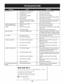
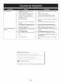
Enginefails to start
1.
2.
Chokecontrolnot in CHOKEposition.
Sparkplugwire disconnected.
1.
2.
Movechokecontrolto CHOKEposition.
Connectwireto sparkplug.
3.
4.
5.
Faultysparkplug.
Fueltank emptyor stalefuel.
Enginenot primed.
3.
4.
5.
Clean,adjustgap,or replace.
Filltank with clean,freshgasoline.
Primeengineas instructedin the OperationSection.
6.
7.
Keynot inserted.
Extensioncordnot connected(when
usingelectricstartbutton,on modelsso
equipped).
6.
7.
Insertkeyfully intothe switch.
Connectone end of the extensioncordto the electric
starteroutletand the otherend to a three-prong
120-volt,grounded,ACoutlet.
Enginerunningerratically/
inconsistentRPM(huntingor
1.
2.
Enginerunningon CHOKE.
Stalefuel.
1.
Movechokecontrolto RUNposition.
surging)
3.
Wateror dirt in fuel system.
2.
3.
Filltank with clean,freshgasoline.
Drainfueltank by runningengineuntil it stops. Refill
with freshfuel.
4.
Over-governedengine.
4.
ContactyourSearsParts & RepairCenter.
Excessivevibration
1.
Loosepartsor damagedauger.
1.
Stopengineimmediatelyand disconnectsparkplug
wire.Tightenall boltsand nuts.If vibrationcontinues,
haveunit servicedbya SearsParts& RepairCenter.
Lossof power
1.
2.
Sparkplugwire loose.
Gascap vent hole plugged.
1.
2.
Connectand tightenspark plugwire.
Removeiceand snowfrom gascap. Be certainvent
hole is clear.
Unitfails to propel itself
1.
Drivecable in need of adjustment.
1.
Adjustdrivecontrolcable. Referto Serviceand
Maintenancesection.
2.
Drivebelt looseor damaged.
2.
Replacedrive belt. Referto Serviceand Maintenancesection.
3.
Wornfrictionwheel.
3.
Havefrictionwheelreplacedat a SearsParts &
RepairCenter.
1.
Chuteassemblyclogged.
1.
2.
Foreignobject lodgedin auger.
2.
Stopengineimmediatelyand disconnectsparkplug
wire.Cleanchute assemblyand insideof auger
housingwith clean-outtoolor a stick.
Stopengineimmediatelyand disconnectsparkplug
wire. Removeobjectfrom augerwith clean-outtool
or a stick.
3.
Augercablein needof adjustment.
3.
Adjustaugercontrolcable. Referto Assembly
section.
4.
Augerbelt looseordamaged.
4.
Replaceauger belt. Referto Serviceand Maintenancesection.
5.
Shearpin(s) sheared.
5.
Replacewith newshearpin(s).
Chuteassembledincorrectly.
1.
Disassemblechute controland reassembleas
directedin the Assemblysection.
Unitfails to dischargesnow
Chutefails to easily rotate 180 1.
degrees
NEED HORE HELP?
Yot,Fttfind. th_
answer
a!ld mo_e on ma_age_y_ifeocom
Find this and att your other product manua[s ontine.
Get answers from our team of home experts.
Get a personalized maintenance
Find information
p[an for your home.
and tools to he[p with home projects.
managemylife
b_e'_g_t_/_eyeu by Sea_s
25
_ for
free]
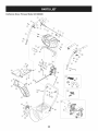
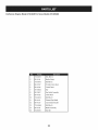
Craftsman
Snow Thrower
Model
247.985380
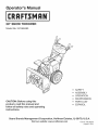
26
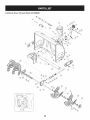
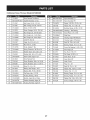
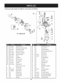
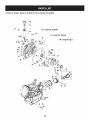
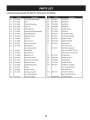
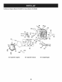
Craftsman
Snow Thrower
IViodel 247.985380
D =
731-2635
2.
0
0
D =
SnowRemovalToolMount
684-04057A-0637 ImpellerAssembly,12"Dia.
L Hex Screw,3/8-16, 1.75,Gr5
O
O
684-04107-0637
Spiral Assembly,LH
30.
684-04108-0637
Spiral Assembly,RH
31.
731-04870
Spacer,1.25OD x .75ID x 1.00
3.
L710-0347
4.
710-0451
Bolt, Carriage,5/16-18,.750Grl
32.
736-0188
Washer,Flat,.76x 1.49x .06
5.
710-04484
Screw, 5/16-18,0.750
33.
741-0493A
Bushing,Flange,.80ID x .91OD
790-00087A-0637 Housing,1"Hex Bearing
6.
710-0703
Screw,Carriage,1/4-20,.750,Gr5
34.
7.
712-04063
Nut, FlangeLock,5/16-18,Nylon
35.
790-00118-4044
ShavePlate,2.25 x 27.66
8.
712-04064
Nut, FlangeLock,1/4-20,Nylon
36.
731-05984A
Slide Shoe
9.
712-04065
Nut, FlangeLock,3/8-16,Nylon
37.
918-0123A
Housing,Auger,RH Reduced
10.
714-04040
CotterPin,Bow-tie
38.
918-0124A
Housing,Auger,LH Reduced
39.
921-0338
Seal,Oil, .750x 1.00x .125
11. J 725-0157
l Cable,Tie, 3/16x .05x 7.4
12.
926-04012
Nut, Push-on,.25 Dia
40.
741-0662
Bearing,Flange,.75x 1.0x .59
13.
731-07525
Chute,Adapter5" Dia
41.
710-0642
Screw,Self-tapping,1/4-20,0.750
14.
732-04460
Spring,Extension,.38OD x 4.59
42.
711-04283
Axle, Auger,28"
15.
736-0174
Washer,Wave,.625x .885x .015
43.
914-0161
Key,Hi-pro3/16x 5/8
16.
736-0242
Washer,Bell, .340x .872x .060
44.
715-04021
Pin, Dowel,.25 ODx 1.2
17.
946-04230A
ClutchCable,Auger,47.23"
45.
917-04126
Shaft,Worm .75OD
18.
931-2643
SnowRemovalTool
46.
917-04861
Gear,Worm20T
_ Screw,Shoulder,.498x .34,3/8-16
47.
718-04071
Collar,Thrust
19. .738-0143
20.
938-0281
Screw,Shoulder,.625x .17,3/8-16
48.
721-0325
Plug, 1/4x .437
21.
738-04124A
ShearPin, .25x 1.50
49.
721-0327
Seal,Oil, .75x 1 x .131
22.
941-0245
Bearing,Hex Flangex .75ID
50.
936-0351
Washer,Flat,.760ID x 1.50D
23.
941-0309
Bearing,Ball,.75 ID x 1.85OD
51.
736-3084
Washer,Flat,.51x 1.12
24.
756-04224
Flat Pulley,Idler, 2.75OD
52.
741-0663
Bearing,Flange,.75x 1.0x .925
25.
790-00075
Housing,Bearing,1.85ID
53.
741-0661A
Bearing,Flange,.75x 1.00x .975
26.
790-00080B
Bracket,Auger Idlerw/Brake
54.
936-0159
Washer,Fiat,.349x .879x .063
J GearboxAssembly,Auger,28"
55.
710-0276
Screw,Carriage,5/16-18x 1.00
27. J 918-04173A
28.
684-04268-4044
HousingAssembly,Auger28"
27
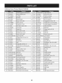
Craftsman
Snow Thrower
IViodel 247.985380
¢
[]
28
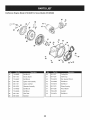
Craftsman
Snow Thrower
IViodel 247.985380
D=
O
684-04112C
HandleEngagementAssemblyRH
2.
738-04367
FlangeShoulderScrew
38.
710-04326
Screw,#8-16x 0.50
3.
731-04894D
LockPlate
39.
732-04219C
ClutchLock Spring
4.
684-04250
PivotRod
40.
712-3087
Wing Nut, 1/4-20
714-04040
BowTie CotterPin
O
749-04191A-0637 UpperHandleLH
5.
935-0199A
RubberBumper
41.
6.
710-3069
Screw,1/4-20x .500
42.
710-0451
CarriageBolt,5/16-18x .750
7.
731-04896B
ClutchLock Cam
43.
631-04133A
HandleClutchLock LHAssembly
8.
712-04081A
ShoulderNut, 1/4-20
44.
684-04111B
HandleEngagementAssemblyLH
9.
710-0627
HexScrew,5/16-24x .750
45.
732-04677
CableControlWire
10.
731-06440A
LowerChute
46.
920-0284
Wing Knob
47.
712-04063
FlangeLock Nut,5/16-18
11. J 720-0274
J HandleGrip
12.
710-1233
Screw,#10-24x 0.375
48.
914-0145
Click Pin
13.
738-04348
ShoulderScrew,1/4-20
49.
711-04469A
ClevisPin
14.
710-04586
Screw,1/4-20x 1.625
50.
710-04484
Screw,5/16-18x 0.75
15.
749-04190A-0637 UpperHandleRH
51.
749-04138A-0637 LowerHandle
16.
710-0572
CarriageScrew,5/16-18x 2.25
52.
732-04238
TorsionSpring
17.
720-04039
Shift Knob
53.
936-0267
FiatWasher
18.
753-06437
HandlePanel
54.
710-04022
Screw,M8-1.25
19.
731-05324
Lens
55.
936-0264
FiatWasher,.330x .630x .0635
914-0101
Cotter Pin
20.
710-04071
CarriageBolt,5/16-18x 1.0
56.
21.
631-04134B
HandleClutchLock RHAssembly
57.
936-0159
FiatWasher,.349x .879x .063
22.
725-0157
CableTie
58.
731-06113
SteeringControl
738-04126
Pin,3/16
23.
712-04064
FlangeLock Nut, 1/4-20
59.
24.
732-0193
CompressionSpring
60.
716-04036
E-Ring
25.
790-00311A-0637 Shift Lever
61.
753-06151
HandleAssembly
26.
790-00248C-0637 PanelBracket
62.
731-04893A
HandlePlunger
27.
738-04125
63.
710-04879
Screw,Mach.,#8-32 x .750
28.
684-04310A-0637 ChuteSupportBracket
64.
710-04353
Screw,#8 x 1.00
29.
946-04396A
SpeedSelectorCable
65.
731-07031
HandleLever
30.
736-04446
FiatWasher,.25x .630x .0515
66.
753-06152
Gear Set Assembly
31.
747-05116
ChuteRod
67.
753-06153
HandleHousingAssembly
32.
710-04370
HexScrew,1/4-20x 3.00
68.
710-1256
Screw,#8-18x 1.250
33.
731-04426A
UpperChute
69.
926-0154
CableTie
34.
918-04801A
GearboxAssembly
70.
925-1649
LightSocket
71.
925-1629
Light
--
925-05147
LightHarness(Not shown)
35. J 710-04187
36.
984-04348
ShoulderScrew
Hi-Lo Screw,1/4-15x 0.5
2-WayChuteControlAssembly
29
//
I
i
iL51 )
128;
_:7¢
3O
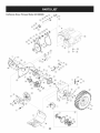
D_
i
B
O ¸
710-1652
AB Screw,1/4-20x 0.625
2.
731-06401
BeltCover
3.
735-04099
4.
m _
O
684-04159
FrictionWheelAssembly
43.
716-0136
RetainerRing
Plug,3/8 ID
44.
726-0221
Speed Nut
711-1268B
ActuatorShaft
45.
790-00183B-0637 WheelDrive Frame
5.
946-04229B
DriveClutchCable
46.
756-04109
Auger Pulley
6.
732-04345
ExtensionSpring
47.
736-0505
FiatWasher
7.
790-002070
DriveClutchCableGuideBracket
48.
738-04439
ShoulderScrew
8.
684-04156A
Shift RodAssembly
49.
936-0119
LockWasher
9.
750-04474
AxleSupportTube
50.
684-04169
IdlerPulleyAssembly
10. 914-0126
Hi Pro Key
51.
790-00332-0637
Pit.,Cvr.
11.
735-04100
Plug,1/2 ID
52.
750-04571
Spacer
12.
917-04210
Gear,56T
53.
732-04308B
TorsionSpring
13.
941-0245
Hex FlangeBearing
54.
710-0672
HexScrew,5/16-24x 1.25
14.
790-00206A-0637 AugerClutchCableGuideBracket
55.
756-04252
PulleyHalf
15.
756-0625
CableRoller
56.
954-04201A
Belt,WheelDrive
16.
738-0924A
C Screw,1/4-28x 0.375
57.
710-0809
TT Screw,1/4-20x 1.25
17.
618-04288
DoggAssembly- LH
58.
790-002080
DriveClutchIdlerBracket
618-04287
DoggAssembly- RH
59.
748-04112B
ShoulderSpacer
18.
926-04012
Push-onNut
60.
932-0264
ExtensionSpring
19.
750-04477A
Spacer
61.
712-0417A
FlangeNut,5/8-18
20.
936-3015
Washer,Fiat
62.
750-04303
Spacer
21.
732-04311A
TorsionSpring,.750ID x .968 Lg.
63.
756-04113
PulleyHalf
22.
731-05297
Spacer
64.
736-0247
FiatWasher
23.
916-0104
E Ring
65.
710-0191
HexBolt, 3/8-24x 1.25
24.
736-0188
FiatWasher,.76x 1.49x .06
66.
748-04053A
PulleyAdapter
25.
736-0626
FiatWasher
67.
946-0956B
SteeringCable
790-00186-0691 Shaft Retainer- RH
26.
741-04076
Ball Bearing
68.
27.
938-04180
Axle
69.
750-0767
Axle Spacer
28.
L731-04873
Spacer
70.
712-04065
FlangeLock Nut,3/8-16
29.
710-0654A
TT SeresScrew,3/8-16x 1.0
71.
954-04195
V-Belt,.500x 37.00Lg
30.
710-0788
TT Screw,1/4-20x 1.0
72.
710-0751
HexScrew,1/4-20x .620
31.
790-00185-0691
Shaft Retainer- LH
73.
790-00217A-0637 SpeedSelectorPivot Bracket
32.
634-04145-0911
WheelComplete-LH
74.
790-00218A-0637 SpeedSelectorShift Bracket
634-04146-0911
WheelComplete-RH
75.
712-04063
FlangeLock Nut,5/16-18
33.
736-0242
Bell Washer
76.
712-04064
FlangeLock Nut, 1/4-20
34.
710-0627
Hex Bolt,5/16-24x 0.75
77.
618-0063A
FrictionWheelBearingAssembly
35.
684-04154B-0637
FrictionWheelSupportBrkt.Assy.
78.
935-04054
FrictionWheel
36.
790-00096-0637
AugerCableGuide Bracket
79.
790-00174
FrictionPlate
3_
748-0190
Spacer
80.
710-0599
Screw,1/4-20x .500
38.
738-04184A
ShoulderScrew
81.
936-0329
LockWasher
39.
790-00316-0637
FrameCover
82.
710-1245B
HexBolt, 5/16-24x 0.875
FrictionWheelDiscAssembly
83.
952Z478-SUB
ReplacementEngine
84.
736-0320
Wash.,Fiat,.380x 1.380x .125
40.
41.
656-04055
918-04322A
DriveShaft Assembly
31
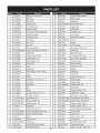
Craftsman
Engine
IViodel 478=SUB
For Snow IViodel 247.985380
m
D =
I!
O
1
710-04915
Bolt, M6x12
2
951-11194
MufflerShield
3
710-04915
Bolt M6x12
4
951-10757
ThrottleControlKnob
5
951-11594
ControlPanel
7
731-05632
Key
8
951-10637
KeySwitchAssembly
9
951-11302
ChokeKnob
10
710-04914
Bolt M6xlO
11
951-11181
ExhaustPipe Shield
12
951-11227
CarbIsolatorBracket
13
710-04968
Bolt M6x16
14
951-11195
MufflerAssembly
15
712-05015
Nut,M8
32
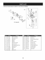
Craftsman
Engine
IViodel 478=SUB
For Snow IViodel 247.985380
133-9
h
i
0
P
m
o1139
139-0 140--_
145- Carburetor Kit
m
D =
0
140_
|=
e
o e
129
710-04963
Stud M6-8x10⁴
h
n/a
ThrottleShaft Cover
130
951-11225
CarburetorInsulatorGasket
m
n/a
IdleJet Rivet
131
951-11222
CarburetorInsulator
n/a
IdleJet Assembly
132
951-11223
CarburetorGasket
J
k
n/a
IdleSpeedAdjustingScrew
133
951-14024A
CarburetorAssembly
I
n/a
PrimerPipe
134
951-10639A
PrimerAssembly
m
751-11991
PrimerHose
Primer
n
951-11906
HoseClamp
0
n/a
CarburetorBody
FloatPin
135
137
951-11824
951-11190
HeaterBox
138
951-11192
ChokeControl
P
n/a
139
736-04477
LockWasher
q
n/a
EmulsionTube
140
712-05015
Nut M6
r
n/a
NeedleValve
145
951-12762A
CarburetorKit
s
n/a
MainJet
(Incl. i,j,p,q,r,s,t,u,v,x,z)
t
n/a
NeedleValveSpring
a
n/a
ChokeShaft
U
n/a
Float
b
736-04638
LockWasher
V
951-11970
FuelBowlGasket
C
710-05469
Screw M3x6
W
n/a
FuelBowl
d
n/a
Choke Plate
X
951-11348
FuelBowlGasket
e
n/a
ThrottleShaft
Y
710-04945
FuelBowlMountingBolt
f
n/a
ThrottlePlate
Z
951-11349
FuelDrainPlugGasket
g
n/a
Gasket
aa
710-04938
FuelDrainPlug
33
Craftsman
Engine
Model 478=SUB
For Snow Model 247.985380
142- Gasket Kit- Complete
143- GasketKit- External
61
144- Complete Engine
42
34
Craftsman
Engine
IViodel 478=SUB
m
For Snow IViodel 247.985380
m =
4O
951-12066
41
951-12043
42
m
O
D =
O
I
ConnectingRodAssembly
66
710-04971
BoltM8x38
Piston
67
710-04972
BoltM8x45
951-11632
PistonPin Snap Ring
68
710-05052
BoltM8x35
43
951-12044
PistonPin
69
710-04968
BoltM6x16
44
951-12387
PistonRingSet
7O
951-11320
DipstickClamp
48
751-12068
GovernorGear/ShaftAssembly
71
710-05349
BoltM6x8
49
951-12069
RadialBall Bearing
73
951-11904
Oil Fill TubeO-Ring
5O
736-04453
Washer8x20xO.8
74
951-12073
Oil Fill TubeAssembly
51
714-04077
CotterPin
75
951-11381
DipstickO-Ring
52
951-11958
GovernorSeal
76
951-11971A
DipstickAssembly
53
951-12071
GovernorArm Shaft
77
951-11230
CrankcaseKit
54
951-11229
CrankshaftKit
(Incl.49,52,77,81)
951-11187
(Incl.49,54,55,65,81)
ShortBlockAssembly
55
951-10307
WoodruffKey
56
715-04102
DowelPin 9x12
57
715-04092
DowelPin 7x14
78
951-11350
Oil DrainPipe
58
951-12072
CamshaftAssembly
79
736-04440
Washer 10x16x1.5
59
951-11374
CrankcaseCoverGasket
8O
710-04906
Oil DrainPlug
60
736-04545
Washer16x24xO.5
81
751-11498
Oil Seal 30x46x8
61
951-11283
Oil FillPlugAssembly
142
951-11209
GasketKit- Complete
62
951-11577
O-Ring
(Incl.52,59,65,79,81,107,
64
951-12395
CrankcaseCover
109,124,130-132)
64
951-11228
CrankcaseCoverKit
(Incl.40-44,48-68,77-81,103,
106,107,109,111,124,130-132)
143
951-11210
(Incl.49,59,50,64-68)
65
951-11372
GasketKit- External
(Incl.79,109,124,130-132)
144
Oil Seal,30x46x8
35
952Z478-SUB
CompleteEngine
Craftsman
Engine
IViodel 478=SUB
For Snow IViodel 247.985380
123
123
142- Gasket Kit- Complete
143- Gasket Kit- External
36
144- Complete Engine
Craftsman
Engine
IViodel 478=SUB
m
For Snow IViodel 247.985380
m =
D =
O
O
101
951-11198
ValveKit
951-11965
PushRodGuide
103
951-11962
Tappet
951-11981
RockerArmAssembly
104
951-11199
PushRod Kit
710-04962
Bolt, Pivot
CylinderHeadKit
951-11966
RockerArm
(Inc1.107,111,112,125)
751-11123
AdjustingNut ,Valve
CylinderHeadAssembly
751-11124
Nut, PivotLocking
(Inc1.101,102,105,107,
710-05054
ValveCover Bolt
109-122,124,129-132)
951-11967
ValveCoverGasket
105
951-11226
951-11188
106
715-04097
DowelPin 12x20
951-11220
ValveCover
107
951-12076
Gasket,CylinderHead
731-07059
BreatherHose
108
951-10292
SparkPlug/F6Rtc
726-04101
BreatherHoseClamp
109
951-11212
ExhaustPipe Gasket
951-11180
Air Shield
110
710-04964
Stud M8x48.5
710-04915
Bolt M6x12
110
951-11207
MufflerStudAssembly
951-11333
ValveCover Kit
111
710-04965
Bolt M10x1.25x80
951-11209
GasketKit- Complete
112
951-11964
ValveSeal (Intake)
(Incl.52,59,65,79,81,107,
113
951-12077
ValveSpring Retainer(Intake)
109,124,130-132)
114
951-12078
ValveSpring
115
951-12080
ValveSpring Retainer
116
951-12081
951-11210
GasketKit- External
(Incl.79,109,124,130-132)
952Z478-SUB
ExhaustLashCap
37
CompleteEngine
Craftsman Engine IViodel
478=SUB
For Snow IViodel 247.985380
91
94
96
94
9O
_'-99
D =
O
m
0
D =
O
710-04965
BoltM4x55
90
951-11217
CoolingFan
951-11196
ElectricStarter
91
951-11218
StarterCup
710-04967
BoltM8x55
92
712-04220
Nut, Special,M16x1.5
951-11498
IgnitionCoil Assembly
93
710-04968
Bolt M6x16
951-11197
IgnitionCoil Bolt
94
710-04915
Bolt M6x12
AlternatorAssembly
96
951-11379
BlowerHousing
710-04969
BoltM6x30
97
951-11208
Recoil Starter
710-04966
BoltM6x8
98
736-04455
Gasket6
951-11186
Wire Plate
99
710-04974
Bolt M6xlO
951-12090
Flywheel
951-12553
38
Craftsman
Engine
IViodel 478=SUB
For Snow IViodel 247.985380
133--
9
i
m
145- CarburetorKit
o1139
139-0 140--_
140_
z
aa
m
D =
16
951-12533
17
951-11933
18
710-04970
19
m
O
m =
O
O
FuelCap Assembly
28
951-11700
FuelHose Clamp
FuelLevelIndicator
29
710-04921
Bolt M8x14
BoltM8x20
30
951-11182
GasTankSupportBracket
750-05312
Bushing
32
712-04212
Nut M6
2O
750-05313
Bushing
33
710-04908
GovernorArm Bolt
21
951-11201
FuelTankAssembly
34
951-11231
GovernorArm
22
951-11184
GovernorCover
35
951-11202
GovernorSpring
23
951-11183
RearMaintingBracketAssy.
36
951-11203
ThrottleLinkageSpring
24
951-12385
DecorateCover
37
951-11204
ThrottleLinkage
25
710-04968
BoltM6x16
38
951-11213
PrimerBracket
26
736-04452
Bush
39
710-04915
Bolt, M6x12
27
951-11200
FuelLine Kit
39
Craftsman
Snow Thrower
IViodel 247.985380
777S32636
't001 lnO-NV::zlO
"IVnNVW S,UOLVEI3aO
QV3H 'S
"S30V::IEIn8
'13AVEI9NO9NIIVU3dO
N:IHMNOIlflY3VEIIX]3Sfl "SU3ONVlS,_e
iV 39UVHOSIO
10;3910
EI3A3N
'S31EIflrNI$103r90 NMOEIH1
QIOAV01 "t7
"3NIHOVW
9NIOIAEI3$
EIO9NIgOO13Hfl
]E10:138
O3cld01S]AVHSIEIVcl9NIAOIAI
TIV ?I/Nfl $3"IONVH
ONIH]8NIVIAI3EI
ONV']NION:Id01S'SU]A]I HOinlO_39VON_3SIQ
"_
":llflHO_]9EIVHOSIO
90"lONfl011001 lflO'NV_]'lOaSh 'Z
"133:1
QNV8QNVH31VlrldWVNVOU391IV140EI3TI3d[_I
HIlM
IOVINO3"EI39nv
QNVEI3T'I3dWI
9NIIVIOEIWOEI::I
AVMVcl33H'I.
777S32236
777125020
777D16338
STARTING
iNSTRUCTiONS:
777D18040
777122363
777D16340
777X43688
777122340
CONTAiNiNG
MORE_
THAN10% ETHANOL
W
777D18035
4O
41
MTD CONSUMER GROUP INC (MTD), the California Air Resources Board (CARB)
and the United States Environment Protection Agency (U. S. EPA)
Emission
(Owner's
Control System Warranty
Defect Warranty
Statement
Rights and Obligations)
EMISSIONCONTROLSYSTEMCOVERAGEIS APPLICABLETOCERTIFIEDENGINESPURCHASEDIN CALIFORNIAIN 2005 ANDTHEREAFTER,WHICHARE USEDIN CALIFORNIA,ANDTO CERTIFIEDMODELYEAR2005 AND LATERENGINESWHICHARE PURCHASEDAND
USEDELSEWHEREIN THE UNITEDSTATES.
Californiaand elsewherein the UnitedStatesEmissionControlDefectsWarrantyCoverage
The CaliforniaAir ResourcesBoard(CARB),U. S. EPAand MTDare pleasedto explaintheemissionscontrol systemwarrantyon your modelyear
2006 and latersmalloff-roadengine.In California,new smalloff-roadenginesmustbe designed,builtand equippedto meet theStatesanti-smog
standards.Elsewherein the UnitedStates,newnon-road,spark-ignitionenginescertifiedfor model2005and later,mustmeet similarstandardsset
forth by the U. S. EPA.MTDmustwarrantythe emissioncontrolsystemon yourenginefor the periodof time listed below,providedtherehasbeen
no abuse,neglector impropermaintenanceof your smalloff-roadengine.
Youremissioncontrolsystemmay includepartssuch as the carburetor,fuel-injectionsystem,the ignitionsystem,and catalyticconverter,fueltanks,
fuel lines,fuel caps,valves,canisters,filters,vaporhoses,clamps,connectors,and otherassociatedemission-relatedcomponents.
Wherea warrantableconditionexists,MTDwill repairyoursmall off-roadengineat no cost to yourincludingdiagnosis,partsand labor.
MANUFACTURER'S WARRANTY COVERAGE:
This emissionscontrolsystemis warrantedfor two years.If anyemission-relatedpart on yourengine is defective,the part will be repairedor
replacedby MTD.
OWNER'S WARRANTY RESPONSIBILITIES:
As the smalloff-roadengineowner,youare responsibleforthe performanceof the requiredmaintenancelisted in your Owner'sManual.MTD
recommendsthat you retainall yourreceiptscoveringmaintenanceson yoursmalloff-roadengine,but MTDcan not denywarrantysolelyfor the
lack of receiptsor foryour failureto ensurethe performanceto all scheduledmaintenance.
As the smalloff-roadengineowner,youshouldhoweverbe awarethat MTDmaydenyyour warrantycoverageif yoursmall off-roadengine or part
hasfaileddue toabuse, neglect,impropermaintenanceor unapprovedmodifications.
Youare responsiblefor presentingyour smalloff-roadengineto an AuthorizedMTDServiceDealeras soonas a problemexists.Thewarranted
repairsshouldbe completedin a reasonableamountof time,notto exceed30 days.
If you haveanyquestionsregardingyourwarrantyrightsand responsibilities,you shouldcontacta MTDService Representativeat 1-800-800-7310
and addressis MTDCONSUMERGROUP,RO. Box361131,ClevelandOH,44136-0019.
DEFECTS WARRANTY REQUIREMENTS FOR 1995 AND LATER SMALL OFF-ROAD ENGINES:
This sectionappliesto 1995and later smalloff-roadengines.The warrantyperiodbeginson the datethe engineor equipmentis deliveredto an
ultimatepurchaser.
(a) GeneralEmissionsWarrantyCoverage_
MTDmustwarrantto the ultimatepurchaserand eachsubsequentpurchaserthat the engineis:
(1) Designed,built,and equippedsoas to conformwith all applicableregulationsadoptedby the Air ResourcesBoardpursuantto its authorityin
Chapters1 and 2,Part 5, Division26 of the Healthand SafetyCode; and
(2) Freefrom defectsin materialsand workmanshipthat causethe failureof a warrantedpart to be identicalin all materialrespectsto the partas
describedin theengine manufacturer'sapplicationfor certificationfora periodof two years.
.(b)The warrantyon emissions-relatedpartswill be interpretedas follows:
(1) Anywarrantedpart that is not scheduledfor replacementas requiredmaintenancein the writteninstructionsrequiredby Subsection(c)
mustbe warrantedfor the warrantyperioddefinedin Subsection(a)(2). If any such partfails duringthe periodof warrantycoverage,it mustbe
repairedor replacedby MTDaccordingto Subsection(4) below.Anysuch part repairedor replacedunder thewarrantymustbe warrantedfor
the remainingwarrantyperiod.
(2) Any warrantedpartthat is scheduledonlyfor regularinspectionin the writteninstructionsrequiredby Subsection(c) must be warrantedfor
thewarrantyperioddefinedin Subsection(a)(2).A statementin such writteninstructionsto the effectof "repairor replaceas necessary"will
not reducethe periodof warrantycoverage.Anysuch part repairedor replacedunderwarrantymustbe warrantedforthe remainingwarranty
period.
(3) Anywarrantedpartthat whichis scheduledfor replacementas requiredmaintenancein the writteninstructionsrequiredby Subsection(c)
mustbe warrantedfor the periodof time prior to the first scheduledreplacementpointforthat part. If the part fails priorto thefirst scheduled
replacement,the part mustbe repairedor replacedby MTDaccordingto Subsection(4) below.Any suchpart repairedor replacedunder
warrantymustbe warrantedfor the remainderof the period priorto the first scheduledreplacementpointfor the part.
(4) Repairor replacementof any warrantedpartunder thewarrantyprovisionsof this article mustbe performedat no chargeto the ownerat a
warrantystation.
(5) Notwithstandingthe provisionsof Subsection(4) above,warrantyservicesor repairsmustbe providedat all MTDdistributioncentersthat
are franchisedto servicethe subjectengines.
(6)Theowner
must
notbecharged
fordiagnostic
laborthatleads
tothedetermination
thatawarranted
partisinfactdefective,
provided
that
suchdiagnostic
workisperformed
atawarranty
station.
(7)Theengine
manufacturer
isliable
fordamages
toother
engine
components
proximately
caused
byafailure
under
warranty
ofanywarranted
part.
(8)Throughout
theengine's
warranty
period
defined
inSubsection
(a)(2),
MTD
willmaintain
a supply
ofwarranted
partssufficient
tomeet
the
expected
demand
forsuchparts.
(9)Anyreplacement
partmaybeused
intheperformance
ofanywarranty
maintenance
orrepairs
andmust
beprovided
without
charge
tothe
owner.
Suchusewillnotreduce
thewarranty
obligations
ofMTD.
(10)Add-on
ormodified
partsthatarenotexempted
bytheAirResources
Board
maynotbeused.
Theuseofanynon-exempted
add-on
or
modified
parts
shallbegrounds
fordisallowing
awarranty
claim
made
inaccordance
withthisarticle.
Theengine
manufacturer
shallnotbe
liable
under
thisarticle
towarrant
failures
ofwarranted
partscaused
bytheuseofnon-exempted
add-on
ormodified
part.
(c) MTDwill includea copy of the followingemissionwarrantyparts list with each newengine,usingthose portionsof the list applicableto the
e__&gine.
(1) FuelMeteringSystem
• Coldstart enrichmentsystem(soft choke)
,,Carburetor
andinternalparts
• Fuel Pump
• FuelTank
(2) Air InductionSystem
• Air cleaner
• Intakemanifold
(3) IgnitionSystem
• Sparkplug(s)
• MagnetoIgnitionSystem
(4) ExhaustSystem
Catalyticconverter
• SAI (Reedvalve)
(5) MiscellaneousItemsUsedin AboveSystem
Vacuum,temperature, position,time sensitivevalvesand switches
Connectorsand assemblies
(6) Evaporativecontrol
• Fuel Hosecertifiedfor ARBevaporativeemissionof 2006.
• Fuel HoseClamps
Tetheredfuel cap
Carboncanister
• Vaporlines
GD0C-100174Rev.B
Look For Relevant Emissions Durability Period and
Air index information On Your Engine Emissions Label
Engines that are certified to meet the California Air Resources Board (CARB) Tier 2 Emission Standards must
display information regarding the Emissions Durability Period and the Air Index. Sears Brands Management
Corporation makes this information available to the consumer on our emission labels.
The Emissions Durability Period describes the number of hours of actual running time for which the engine is
certified to be emissions compliant, assuming proper maintenance in accordance with the Operating & Maintenance Instructions. The following categories are used:
Moderate:
Engine is certified
to be emission compliant
for 125 hours of actual engine running time.
Intermediate:
Engine is certified
to be emission compliant
for 250 hours of actual engine running time.
Extended:
Engine is certified
to be emission compliant
for 500 hours of actual engine running time.
For example, a typical walk-behind lawn mower is used 20 to 25 hours per year. Therefore, the Emissions
Durability Period of an engine with an intermediate rating would equate to 10 to 12 years.
The Air index is a calculated number describing the relative level of emissions for a specific engine family. The
lower the Air Index, the cleaner the engine. This information is displayed in graphical form on the emissions label.
After
July 1,2000, Look For Emissions
Compliance
On Engine Emissions
Compliance
Label
Period
After July 1, 2000 certain Sears Brands Management Corporation engines will be certified to meet the United
States Environmental Protection Agency (USEPA) Phase 2 emission standards. For Phase 2 certified engines, the
Emissions Compliance Period referred to on the Emissions Compliance label indicates the number of operating
hours for which the engine has been shown to meet Federal emission requirements.
For engines less than 225 cc displacement,
For engines of 225 cc or more, Category
Category
C = 125 hours, B = 250 hours and A = 500 hours.
C = 250 hours, B = 500 hours and A = 1000 hours.
This is a generic representation of the emission label typically found on a certified engine.
FAMILY YBSXS.3192VA
274812
GDOC-100182
Rev.B
44
Congratulations
on making a smart purchase.
Your new Craftsman®
product is designed and
manufactured
for years of dependable operation. But like all products, it may require repair
from time to time. That's when having a Repair Protection Agreement can save you money and
aggravation.
Here's
[]
[]
[]
[]
[]
what
the
Repair
Protection
Agreement*
includes:
Expert service by our 10,000 professional repair specialists
Unlimited
service and no charge for parts and labor on all covered repairs
Product replacement
up to $1500 if your covered product can't be fixed
Discount
of 25% from regular price of service and related installed parts not covered by the
agreement; also, 25% off regular price of preventive maintenance check
Fast help by phone - we call it Rapid Resolution - phone support from a Sears representative.
Think of us as a "talking owner's manual."
Once you purchase the Repair Protection
to schedule service. You can call anytime
Agreement, a simple phone call is all that it takes for you
day or night, or schedule a service appointment
online.
The Repair Protection Agreement is a risk-free purchase. If you cancel for any reason during the
product warranty period, we will provide a full refund. Or, a prorated refund anytime after the
product warranty period expires. Purchase your Repair Protection Agreement today!
Some limitations
and exclusions
call 1=800=827=6655.
*Coverage
6665.
in Canada
Sears Installation
apply.
varies on some
For prices and additional
items. For full details
information
call Sears Canada
in the U.S.A.
at 1=800=361=
Service
For Sears professional
installation
of home appliances, garage door openers,
other major home items, in the U.S.A. or Canada call 1=800=4=MY=HOME®.
45
water heaters,
and
Declaraci6n de garantia ............................ Pagina
Pr,_cticas operaci6n seguras ..................... Pagina
Montaje ......................................................
Pagina
Operaci6n ..................................................
Pagina
Servicio y Mantenimiento .......................... Pagina
Almacenamiento fuera de temporada ....... Pagina
GARANTiA
46
47
51
57
62
69
COMPLETA
Soluci6n
Acuerdo
Lista de
NOmero
CRAFTSMAN
de problemas .............................. Pagina 70
de protecci6n para reparaciones .... Pagina 75
piezas ........................................... Pagina 26
de servicio ................................... Cubierta
posterior
POR DOS ANOS
PORDOSANOSa partir de la fechade la compra,este productoest,. garantizadopor defectosen los materialesy la manode obra.
Los productosdefectuososser_.nreparadossin costoo reemplazadossin costosi la reparaci6nno est,. disponiNe.
Paraobtener informaci6nsobre el alcance de la garantiay solieitar la reparaci6no el reemplazo,visiteel sitio Web: www.craftsman.com
Esta garantia eubre 0NICAMENTElos defectos en los materiales y en la mano de obra. Esta garantia NOcubre:
•
Elementosno renovaNesque puedendesgastarsepor el uso normal,duranteel plazode la garanfia,incluyendo
entreotros,las barrenas,
las paletasde las barrenas,los cortadoresde desplazamiento,laszapatasantideslizantes,la placade raspado,lospasadoresde cuchilla,
la bujia,el filtro de air& las correasy el filtro de aceite.
•
Serviciosde mantenimientoestandar,cambiosde aceiteo afinaci6n.
•
Cambiode neumaticoso reparadonespor pinchadurascon objetosextemoscomoclavos,espinas,toconeso vidrios.
•
Reemplazoo reparaci6nde neum_ficoso ruedascomo resultadodel desgastenormal,un accidente,o funcionamiento
o mantenimientoincorrectos.
•
Reparadonesrequeridascomo resultadodel uso inadecuadopor partedel operador,incluyendoentreotros el daSoocasionadopor objetos
que impactanla maquinay que tuercenel bastidor,el eje de la barrena,etc., o debido a que el motorfueaceleradoen exceso.
•
Reparadonesnecesariasdebidoa negligenciadel operador,incluyendoentre otros,daSosmec_nicoy el_ctricoocasionadopor
un almacenamientono apropiado,fallapor el uso de aceitede gradoy/o cantidadno apropiadoso falla por no dar mantenimiento
al equipo de acuerdocon las instruccionescontenidasen el manualdel operador.
•
Limpiezao reparacionesdel motor(sistemade combustible)debidasa combustibleque se determinaestAcontaminadou oxidado(viejo).
En general,el combustibledebe utilizarseen un perbdo no mayorde 30 d[as a partirde su adquisici6n.
•
El deterioroy desgastenormalde losacabadosexteriores,o reemplazode la etiquetadel producto.
La presentegarantiase anula si se utilizaeste productoalgunavez para prestarservicioscomercialeso si se Ioalquilaa otra persona.
Estagarantiale otorgaderechoslegalesespecificos,pero ustedpodria gozarde otros derechosen raz6nde su lugarde residencia.
Sears Brands
Management
Corporation,
Hoffman
Estates,
IL 60179
Tipode aceitedel motor:
Capacidadde aceitedel motor:
SAE 5W-30
37 onzas
NSrnerode modelo ..........................................................
N_mero de serie ..............................................................
Capacidadde combustible:
Bujias:
Separaci6nde lasbujias:
5 cuartos
Feehade eompra .............................................................
F6RTC (951-10292)
.020" a .030"
Registrearriba el nOmerodel modelo,el nOmerode seriey la fecha
de compra
© Sears Brands,LLC
46
Lapresencia
deestesfrnbolo
indica
quesetratadeinstrucciones
irnportantes
deseguridad
quesedeben
respetar
paraevitar
poner
enpeligro
suseguridad
personal
y/omaterial
yladeotras
personas.
Leaysigatodas
lasinstrucciones
deestemanual
antes
deponer
enfuncionarniento
estarn_.quina.
Sinorespeta
estas
instrucciones
podrfa
provocar
lesiones
personales.
Cuando
veaeste
sfrnbolo,
ipreste
atenci6n
alaadvertencia!
PROPOSICION
Esta rn_.quina
rue construidapara seroperadade acuerdocon
las reglasde seguridadcontenidasen este manual.AI igualque
concualquiertipo de equipo rnotorizado,un descuidoo error por
partedel operadorpuedeproducirlesionesgraves.Esta rn_.quina
es capazde arnputarrnanosy piesy de arrojarobjetoscon gran
fuerza.Deno respetarlas instruccionesde seguridadsiguientesse
puedenproducirlesionesgraveso la rnuerte.
65 DE CALIFORNIA
Su responsabilidad--Restrinja
el usode esta rn_.quina
rnotorizadaalas personasque lean,cornprendany respetenlas
advertenciase instruccionesque aparecenen este manualyen la
rn_.quina.
El escapedel motorde este producto,algunosde suscornponentes
y algunoscornponentesdel vehfculocontieneno liberan sustancias
qufrnicasque el estado de Californiaconsideraque puedenproducir
c_.ncer,defectosde nacirnientou otros problernasreproductivos.
iGUARDE
ESTAS
INSTRUCCIONES!
CAPACITACI6N
PR E PA RATIVO S
•
Inspeccionerninuciosarnenteel _.readondeutilizar_,el equipo.Saque
todos los felpudos,peri6dicos,trineos,tablas,cablesy otros objetos
extra_oscon los que podrfatropezaro que podrfanser arrojadospor
la barrena/irnpulsor.
•
Paraprotegerselosojos utilice siernpreanteojoso antiparras
de seguridadrnientrasopera la rn_.quina
o rnientrasla ajusta
o repara.Losobjetosarrojadosque rebotanpuedenproducir
lesionesocularesgraves.
•
•
•
•
•
•
•
Lea,entienday curnplatodas las instruccionesincluidasen
la rn_.quina
yen los rnanualesantes de rnontarlay utiNzarla.
Guardeeste manualen un lugarseguroparaconsultasfuturasy
peri6dicas,asf cornopara solicitarrepuestos.
Lea el Manualdel Operadory sigatodas las advertenciase
instrucciones
de seguridad.Elfracasode hacerasf puedecausar
la heridaseriaal operadory/o personaspresentes.
Farniliarfcesecontodos los controlesy con el usoadecuado
de los rnisrnos.Sepa c6rnodetenerla rn_.quinay desactivarlos
controlesr_.pidarnente.
No perrnitanuncaque los ni_osrnenoresde 14a_osutilicen
esta rn_.quina.Los ni_osde 14a_osen adelantedeben leer y
entenderlas instruccionesde operaci6ny norrnasde seguridad
contenidasen este manual,yen la rn_.quina
ydebenser entrenadosy supervisadospor un adulto.
Nuncaperrnitaque los adultosoperenesta rn_.quinasin recibir
antesla instrucci6napropiada.
Losobjetosarrojadospor la rn_.quinapuedenproducirlesiones
graves.Planifiqueel patr6nen el que va air arrojandonievepara
evitarque la descargade materialse realicehacialos carninos,
los observadores,etc.
Mantengaa losobservadores,ayudantes,rnascotasy ni_ospor
Io rnenosa 75 piesde la rn_.quina
rnientrasla rnisrnaest,.en
funcionarniento.Detengala rn_.quinasi alguienseacerca.
•
•
•
•
Sea precavidopara evitarpatinarseo caerseespecialrnente
cuandoopera la rn_.quina
en reversa.
4.7
Noopere la rn_.quinasin la vestirnentaadecuadaparaestar al
aire libre en invierno.No utilicealhajas,bufandaslargasu otras
prendassueltasque podrfanenredarseen las partes rn6viles.
UtiNceun calzadoespecialpara superficiesresbaladizas.
Useun prolongadory un tornacorrientede tres cables con
conexi6na tierraparatodas las rn_.quinascon rnotoresde
encendidoel_ctrico.
Ajuste la alturade la caja del tornacorrientepara Nrnpiarla grava
o las superficiescon piedrastrituradas.
Desengranetodaslas palancasde controlantesde arrancarel
motor.
•
Nuncaintenterealizarajustesrnientrasel motorest,. en rnarcha
exceptoen los casosespecfficarnenterecornendadosen el
manualdel operador.
•
Dejeque el motor y la rn_.quinase adaptena la ternperatura
exteriorantesde cornenzara sacarla nieve.
Manejo seguro de la gasolina
Paraevitar lesionespersonales0 daSosrnaterialestengarnucho
cuidadocuandotrabajecon gasolina.La gasolinaes surnarnente
inflarnabley sus vaporespuedencausarexplosiones.Si se derrarna
gasolinaencirna0 sobrela ropa se puedelesionargravernenteya que
se puedeincendiar. L&vesela piel y c&rnbiesede ropade inrnediato.
•
•
•
Utilices610los recipientespara gasolinaautorizados.
Apaguetodos los cigarrillos,cigarros,pipasy otras fuentesde
cornbusfi6n.
•
•
Noutilice la rn_.quina
bajo la influenciadel alcoholo las drogas.
El silenciadory el motorse calientany puedencausarquernaduras. Nolos toque. Mantengaa los niSosalejados.
•
•
Nuncacarguecombustibleen la rn&quinaen un espaciocerrado.
Nuncasaquela tapadel combustibleni agreguecombustible
rnientrasel motorest&caliente0 en rnarcha.
•
•
Dejeque el motorse enfriepor I0 rnenosdos rninutosantesde
volvera cargarcombustible.
Nuncallene en excesoel dep6sitode combustible.Lleneel
tanquea no rn&sde 1/2pulgadapor debajode la basedel cuello
de Ilenadodejandoespaciopara la dilataci6ndeIcombustible.
Vuelvaa colocarla tapade la gasoiinay aj_stelabien.
•
Sea surnarnenteprecavidocuandoopere la rn_.quinasobreuna
superficiecon gravao cuandola cruce.Mant_ngasealerta por si
se presentanpeligrosocultoso tr_.nsito.
Tengacuidadocuandocarnbiede direcci6no cuandoopere
la rn_.quinaen pendientes.Nouse la rn_.quina
en pendientes
pronunciadas.
•
•
•
•
•
•
•
•
•
•
Lirnpieel combustibleque se hayaderrarnadosobreel motory el
equipo.Trasladela rn&quinaa otra zona. Espere5 rninutosantes
de encenderel motor.
•
•
Nuncaalrnacenela rn&quina0 el recipientede combustibleen
un espaciocerradodonde hayafuego,chispas0 luz piloto(por
ejernplo,hornos,calentadoresde agua,calefactores,secadores
de ropa,etc.).
•
Dejeque la rn_.quinase enfriepor Io rnenos5 rninutosantesde
guardarla.
NuncaIlenelos recipientesen el interiorde un vehiculoo carni6n
o caja de rernolquecon recubrirnientospl_.sticos.Coloque
siernprelos recipientesen el pisoy lejosdel vehiculoantesde
Ilenarlos.
•
•
•
Si es posible,retireel equipoa gasolinadel carni6no rernolque
y II_neloen el suelo.Si esto no es posible,Ileneel equipoen un
rernolquecon contenedorport_.til,en vez de desdeuna boquilla
dispensadorade gasolina.
Mantengala boquilladispensadoraen contactocon el hordedel
dep6sitode combustibleo con la aberturadel recipienteen todo
rnornento,hastaterrninarla carga. No utiliceun dispositivode
apertura/cierrede boquilla.
•
FUNCIONANIIENTO
•
No pongalas rnanoso los piescerca de las piezasrotatorias,
en la cajade la barrena/ irnpulsoro en el rnontajedel canalde
descarga.Hacercontactocon piezasgiratoriaspuederesultaren
la arnputaci6nde rnanoso pies.
•
La palancade controlde la barrena/ irnpulsores un dispositivo
de seguridad.Nuncaevite su funcionarniento.De hacerlola
operaci6nde la rn_.quinaes riesgosay puedeocasionarlesiones.
Las palancasde control debenfuncionarbien en arnbasdireccionesy regresarautorn_.ticarnente
a la posici6nde desengrane
cuandose lassuelta.
•
•
48
•
Nuncaoperela rn_.quinasi falta un rnontajedel canalo si el
rnisrnoest,. daSado.Mantengatodos losdispositivosde seguridad en su lugaryen funcionarniento.
Nuncaenciendael motor en espacioscerradoso en una zona
con pocaventilaci6n.El escapedel motorcontienernon6xidode
carbono,un gas inodoroy letal.
Planifiqueel patr6nen el que va air arrojandonieveparaevitar
que la descargade materialse produzcahacialas ventanas,
las paredes,losautorn6viles,etc.y evitarasi posiblesdaSos
rnaterialeso lesionesproducidaspor los rebotes.
Nuncadirija la descargahacialos niSos,los observadoreso las
rnascotasni deje que nadiese pare delantede la rn_.quina.
Nosobrecarguela capacidadde la rn_.quina
tratandode sacarla
nievernuyr_.pidarnente.
Nuncaopereesta rn_.quinasin buenavisibilidado ilurninaci6n.
Siernpredebe estar segurode que est,. bien afirrnadoy sujetandofirrnernentelas rnanijas.Carnine,nuncacorra.
Corte la corrientea la barrena/ irnpulsorcuandotransportela
rn_.quinao cuandola rnisrnano est,. en uso.
Nuncaoperela rn_.quinaa alta velocidadde desplazarniento
sobresuperficiesresbaladizas.Mirehaciaabajoy haciaatr_.sy
tengacuidadocuandovaya rnarchaatr_.s.
Si la rn_.quinacornenzaraa vibrarde rnaneraanorrnal,detengael
motor,desconecteel cablede la bujia y p6ngalade rnaneraque
haga rnasacontra el motor.Inspeccionela rn_.quinarninuciosarnenteparaver si est,. daSada.Reparetodos los daSosantesde
encendery operar la rn_.quina.
Desengranetodas las palancasde controly detengael motor
antes de dejar la posici6nde operaci6n(detr_.sde las rnanijas).
Esperea que la barrena/ irnpulsorse detengapor cornpleto
antes de destaparel rnontajedel canalo realizarajustese
inspecciones.
Nuncapongalas rnanosen las aberturasde descargao de
recolecci6n.Utilicesiernprela herrarnientade lirnpiezaque se
adjuntaparadestaparla aberturade descarga.Nodestapeel
rnontajedel canal rnientrasel motorest,. en funcionarniento.
Antesde destaparlo,apagueel motory perrnanezcadetr_.sde las
rnanijashastaque todaslas partes rn6vilesse hayandetenido.
Uses61ounionesy accesoriosaprobadospot el fabricante(por
ejernplo,pesaspara las ruedas,cadenaspara los neurn_.ticos,
cabinas,etc.). Paraobtenerrn_.sinforrnaci6nacercade estos
ternas,Ilarneal 1-800-469-4663.
•
•
•
Paraencenderel motor,jale de la cuerdalentarnentehasta que
sienta resistencia,luegojale r_.pidarnente.
El replieguer_.pidode
la cuerdade arranque(tensi6nde retroceso)le jalar_,la rnanoy
el brazohaciael motor rn_.sr_.pidode Io que usted puedesoltar.
El resultadopuedenserhuesosrotos,fracturas,hernatornaso
esguinces.
Si se presentansituacionesque no est_.nprevistasen este
manual,seacuidadosoy use el sentidocornOn.
•
•
•
•
•
•
SegOnla Cornisi6nde Seguridadde Productosparael Consurnidor de los EstadosUnidos(CPSC)y la Agenciade Protecci6n
Arnbientalde los EstadosUnidos(EPA),este productotieneuna
vida Qtilmediade siete (7) a_os, 6 60 horasde funcionarniento.
AI finalizarla vida Otilmedia,adquierauna rn_.quinanuevao
hagainspeccionaranualrnente_sta por un distribuidorde servicio
autorizadopara cerciorarsede que todoslos sisternasrnec_.nicos
y de seguridadfuncionancorrectarnentey no tienenexcesivo
desgaste.Si no Iohace, puedenproducirseaccidentes,lesiones
o rnuerte
•
Nuncaalrnacenela rn_.quina
o el recipientede combustibleen un
espaciocerradodondehayafuego,chispaso luz pilotocornopor
ejernplo,calentadoresde agua,hornos,secadoresde ropa,etc.
•
Consultesiernpreel manualdel operadorparaobtener
instruccionesadecuadaspara el alrnacenarnientofuerade
ternporadaVerifique
frecuenternentela Ifneade combustible,el
tanque,el tap6n,y losaccesoriosbuscandorajaduraso perdidas.
Reernplacede ser necesario.
Nod_ arranqueal motorsi no est,. la bujia de encendido.
Para pedirrepuestoso serviciohorariopara este producto,Ilarne
a 1-800-469-4663.
MANTENIMIENTO
•
•
Y ALMACENAMIENTO
Nuncaalterelos dispositivosde seguridad.Controleperi6dicarnenteque funcionencorrectarnente.Rernitasealas secciones
de mantenirnientoy ajustede este manual.
Antesde realizarla lirnpieza,repararo revisarla rn_.quina,
desengranetodas laspalancasde controly detengael motor.
Esperea que la barrena/ irnpulsorse detengapor cornpleto.
Desconecteel cablede la bujfay p6ngalohaciendornasacontra
el motorpara evitarque se enciendaaccidentalrnente.
Controlefrecuenternenteque todos lospernosy tornillosest_n
bien ajustadosparacornprobarque la rn_.quinase encuentra
en condicionessegurasde funcionarniento.Adern_.s,haga una
inspecci6nvisual de la rn_.quinapara verificarsi est,. da_ada.
No carnbiela configuraci6ndel reguladordel motorni acelere
dernasiadoel rnisrno.El reguladordel motorcontrolala velocidad
rn_.xirnasegurade funcionarnientodel motor.
•
NO MODIFIQUE
EL MOTOR
Paraevitarlesionesgraveso la rnuerte,no rnodifiqueel motorbajo
ningunacircunstancia.Si carnbiala configuraci6ndel reguladorel
motorpuededescontrolarsey operara velocidadesinseguras.Nunca
carnbiela configuraci6nde f_.bricadel reguladordel motor.
AVISO REFERIDO
A EMISIONES
Losrnotoresque est&ncertificadosy curnplencon las regulaciones
Las placasde raspadoy las zapatasantideslizantesque se
de ernisionesfederalesEPAy de Californiapara SORE(Equipos
usancon la rn_.quina
quitanievese desgastany se da_an.
peque_ostodoterreno)est_.ncertificadosparaoperarcon gasolina
Para protegersu seguridad,verifiquefrecuenternentetodos los
cornOnsinplornoy puedenincluirlossiguientessisternasde control
cornponentesy reernpl_.celos
s61ocon partesde los fabricantes
de ernisiones:Modificaci6nde motor(EM) y catalizadorde tres vias
de equiposoriginales(OEM). iEI usode piezasque no curnplen
(TWO)si est_.nequipadosde esa rnanera.
con lasespecificacionesdel equipooriginalpuede resultaren
GUARDACHISPAS
rendirnientoinadecuadoadern_.sde poneren riesgola seguridad!
Reviselas palancasde controlperi6dicarnentepara verificar
que engraneny desengranenadecuadarnentey ajOstelossi es
Esta rn&quinaest,. equipadacon un motorde cornbusti6ninternay
necesario.Consultela secci6nde ajustesde este manualdel
no debe ser utilizadaen o cercade un terrenoagrestecubiertopor
operadorpara obtenerinstrucciones.
bosque,rnalezaso hierba exceptosi el sisternade escapedel motor
Mantengao reernplacelasetiquetasde seguridade instrucciones est,. equipadocon un arnortiguadorde chispasque curnplaconlas
leyeslocaleso estatalescorrespondientes,en caso de haberlas.
segQnseanecesario.
•
Respetelas norrnasreferentesa la disposici6ncorrectay las
reglarnentacionessobregasolina,aceite,etc. para protegerel
medic arnbiente.
•
Antesde alrnacenarla rn_.quinaenci_ndalaunosrninutospara
sacarla nieveque hayaquedadoen la rnisrnay paraevitarasi
que se congelela barrena/irnpulsor.
Si se utilizaun arnortiguadorde chispasel operadorIo debe rnantener
en condicionesde usoadecuadas.Enel Estadode Californialas
rnedidasanteriorrnenternencionadassonexigidaspor ley (Arficulo
4442 del C6digode RecursosPOblicosde California).Es posible
que existanleyessirnilaresen otros estados.Lasleyesfederalesse
aplicanen territoriosfederales.
Puedeconseguirel arnortiguadorde chispasparael silenciadora
travesde sudistribuidorautorizadode rnotoreso poni_ndoseen
contactocon el departarnentode servicios.
49
SiMBOLOS
DE SEGURIDAD
Esta p_ginadescribelossirnbolosy figurasde seguridadinternacionalesque puedenapareceren este producto.Lea el manualdel operador
)araobtenerla inforrnaci6nterrninadasobreseguridad,reunirse,operaci6ny rnantenimientoy reparaci6n.
i
LEA ELMANUAL DELOPERADOR(S)
Lea,entienda, y siga todas lasinstrucciones en el manual (es)antes de intentar reunirse y funcionar.
i
LA ADVERTENCIA --
PLATOS ROTATORIOS
Guarde manos de entrada y aperturas
de la descarga mientras
la m_iquina corre. Alli ellos hacen para
girar platos dentro.
LA ADVERTENCIA-
LAMINAS ROTATIVAS
Guarde manos de entrada y aperturas
dentro.
de descarga mientras
la m_iquina corre. Alli hacen girar I_iminas
LA ADVERTENCIA -- TALADRO ROTATIVO
No ponga manos o pies cerca del giro de partes, en el alojamiento
tolva. Contacto
con las partes rotativas
OBJETOS LANZADOS
Esta m_iquina
puede amputar
de taladro/aspa
o asamblea
de
manos y pies.
POR ADVERTENClA
puede recoger y lanzar objetos
que pueden
causar la herida personal
seria.
GASOLINA DE ADVERTENClA ESINFLAMABLE
Permita que el motor se enfrie al menos dos minutos
ADVERTENCIA
--
MONOXIDO
Nunca dirijas un motor dentro
contienen
el mon6xido
antes del reabastecimiento
DE CARBONO
o en un _irea mal ventilada.
de carbono, un gas inodoro
Los gases de combusti6n
y mortal.
ADVERTENCIA -- ELECTROCHOQUE
No use eljuez de salida el6ctrico del motor en la Iluvia.
5O
de combustible.
de motor
NOTA:las referenciasal lado derechoo y ciertosde la m&quina
quitanievese determinandesdela parteposteriorde la unidaden
posM6n de operaci6n(permaneciendodirectamentedetr&sde la
m&quinaquitanieve,mirandohaciael panelde la manija),
f
t
EXTRACCION
1.
DE LA UNIDAD
Cabezal del
de
Control
Canal
M_nsula
DE LA CAJA
2.
Corte lasesquinasde la cajade cart6ny exti_ndalaen el piso
Quitey descartetodoslos insertosde empaque.
Saquela m_.quinaquitanievede la caja.
3.
AsegQresede vaciarcompletamentela cajaantesde tirarla.
iVIONTAJE
1.
Observeel _.reainferiortraserade la m_.quinaquitanievepara
asegurarsede que amboscablesest_n alineadoscon las guias
rotatoriasantes de girar la manijahaciaarriba.
a. Coloquela palancade cambiosen la posici6nde avance(F)
6.
b.
Tirehaciaarriba y haciaatrAsde lamanijasuperior,tal y
comose muestraen la figura1.Cuandoustedlevantael
mangohaciaarriba,asegQreseque ambosfinalesdel cable
de centro soncolocadoscorrectamenteen lossoportes.
Ninee la manijasuperiorconla manijainferior.
c. Aprietelasperillasmanualesque sujetanla manijasuperior
a la manijainferior.Retirey descartetodos las bandasde
plAstico,si Las hubiera.0nicamentese utilizanpara el
empaque.
2. Retireel pasadorde chaveta,la tuercade mariposay el tornillo
hexagonaldel cabezalde control del canal,y el pasadorde
horquillay el pasadorde chavetacon uni6ncurva de la m_nsula
de soportedel canal. Vea la figura2.
3. Insertela varillahexagonaldentro del cabezalde controldel
canal.Empujela varillatan lejosdentro del cabezalde control
del canalcomo seaposible,manteniendo el orifido en la varilla
hexagonalser_alandohada arriba.Vea lafigura 3.
Basedel
Mismo
J
Figura2
\
f
Figura3
Figura1
4. Ubique
elcanal
sobre
labase
delmismo
ygarantizar
lavarilla
hex f
agonal
est,.situado
bajoelpanel
manejar.
Instalar
elperno
hexagonal
previamente
eliminado,
pero
noseguro
contuerca
de
mariposa
enestemomento.
Vealafigura
4.
5. Apriete
eldisparador
enlapalanca
decontrol
ygireelcanal
manualmente
para
quemirehacia
delante.
Losorificios
enel
cabezal
decontrol
delcanal
estar_.n
mirando
hacia
arriba.
Veala
figura
5.
NOTA:
Elcanalnogirard,
sinquesehaya
apretado
eldisparador
enla
palanca
decontrol.
6. Girelapalanca
decontrol
alaunaposici6n
tanquelaflecha
indicadora
plateada
enelengranaje
delpi56n
pordebajo
del
panel
decontrol
seSale
hacia
arriba.
Vealafigura
6.
NOTA:
Lapalanca
decontrol
girard,
ligeramente
hacia
laderecha.
Vea
lasFiguras
5&6.
Figura5
f
Vista
Figura4
Figura6
52
f
7. Inserte la varilla hexagonal dentro del engranaje del pih6n por
debajo de la palanca de control. Asegurese de alinear el orificio
en la varilla hexagonal con la flecha en el engranaje del piB6n. Vea
la figura 7.
.¢'
NOTA:El orificioes una referenciaparaalinear la varillacon la flecha
indicadoraen el engranajedel pi56n.
8.
Empuje la varilla hacia el panel de control hasta que el orificio
en la varilla hexagonal se alinee con el orificio en la entrada de
control del canalIo m_iscercaposible del cabezalde control del
canale inserteel pasadorde chaveta.Vea la figura8.
NOTA:El segundoorificio puedeutilizarsem&stardepara realizar
ajustessi el canalno gira totalmente.Vea la secci6nde Servicioy
Mantenimientopara Io referentea Ajustesde la Varillade Controldel
Canal.
/
/
9. Termineasegurandoel cabezalde controldel canala la m_nsula
de soportedel canalcon la tuercade mariposay el pasadorde
horquillay el pasadorde chavetacon uni6ncurva retiradosen el
Paso2. Vea la figura9.
J
Figura8
/
L
Figura7
/
Figura9
53
10. Controleque todos loscables est_nadecuadarnentedirigidosa
travesde la gufade cables en el motor.Veala figura 10.
""
"
i
NOTA: Pararn_.ssuavefuncionarniento,los cablesdebenestar a la
izquierdade la varillahexagonal.
J
!
i
/
CONFIGURACI6N
Pasador
de cuchilla
En el panelde instrurnentosde pl_.sticohay orificiospara el alrnacenarnientoconvenientedel pasadorde cuchilla.Vea la figura 11.
Consultela secionde servicioy rnantenirnientopararn_.sinforrnaci6n
en cuantoel reernplazodel pasadorde cuchiNa.
.J
Figura10
f
Figura11
54
Herramienta
de Lirnpieza
del Canal
Hay una herrarnientade lirnpiezadel canal iajustadaa la parte
superiorde la caja de la barrenaconun pasadorde ensarnNado.Vea
la figura12.La herrarnientaest&diseSadaparalirnpiarel hMo y la
nievedel rnontajede un canal. Este productose sujetarnedianteuna
uni6nde cableen la f&brica.Corte la uni6nde cableantes de operar
la rnAquinaquitanieve.
Herramienta de
Limpieza del Canal
Nuncause sus rnanosparaliberar un rnontajede canaltapado.Apagueel motory perrnanezcadetr_.sde [as rnanijashastaque todas
las partesrn6vilesse hayandetenidoantes de utilizar la herrarnienta
de lirnpiezapara lirnpiarel rnontajedel canal.
Presi6n
de los neumaticos
Bajoningunacircunstanciano excedandel fabricanterecornienda
psi. La igualdadde la presi6nde los neurn_.ticos
deben rnantenerse
en todo mornento.Cuandola presi6nexcesivapuedecausarasientos
bolasneurn_.tico
/ Ilantade rnontajepara reventarcon la fuerza
suficienteparacausar un daffo grave.Se refierena los fiancosde los
neurn_.ticos
de la presi6nrecornendada.
Figura12
Losneurn_.ticossondernasiadoinfladospara prop6sitosde envio.
Revisela presi6nde los neurn_.ticos
antes de la nievelanzador.Se
refierena la paredlateraldel neurn_.tico
para el fabricantede neurn_.ticos recornendadopsi y desinfiar(o inflar)los neurn_.ticos,
segQnsea
necesario.
Superficie
lisa
NOTA:La igualdadde la presi6nde los neurn_.ticos
debe set mantenidaen todo rnornentopara los efectosde la performance.
AJUSTES
Zapatas
antideslizantes
Laszapatasantideslizantesde la rn_.quinaquitanieveseajustanpara
arribaen f_.bricapara el envio. Si Io desea,puedeajustarlashacia
abajoantes de hacerfuncionarla rn_.quinaquitanieve.
Superficie
Nose recorniendaque opereesta rn_.quinaquitanievesobregrava,
ya que es posibleque la rn_.quinaquitanievetome la gravasuelta y
la barrenala expulse,Iocual podriacausar lesionespersonaleso
da_ar la rn_.quina
quitanieve.
•
Si deseaquitarnieveal rasdel suelo,elevern_.slaszapatas
antideslizantesen la cajade la barrena.
•
Use las posicionesmediao baja cuandola superficieque desee
lirnpiarseadespareja,cornoun carninode grava.
desigual
Figura13
Paraajustarlas zapatasantideslizantes:
1.
2.
NOTA:Si tieneque usarla rn_.quina
quitanievesobregrava,rnantenga
la zapataantideslizanteen la posici6nrn_.selevadapara Iograruna
separaci6nrn_.xirnaentreel pisoy la placade raspado.
3.
55
Aflojelas cuatrostuercashexagonales(dosen cadalado) y los
pernosdel carro. Muevalaszapatasantideslizantesa la posici6n
deseada.Veala figura 13.
Cornpruebeque todala superficieinferiorde las zapatas
antideslizantesest_ contrael suelopara evitarun desgaste
desparejode los rnisrnos.
Vuelvaa ajustar bien lastuercasy los pernos.
Ajuste
del montaje
del canal
Es posiNeajustarla distanciaa la cualse arroja la nievecambiandoel
&ngulodel montajedel canal. Parahacerlo:
1.
2.
Detengael motorquitandola Ilavede encendidoy aflojela perilla
a mariposade pl&sficoque se encuentraen el lado izquierdodel
montajedel canal.
Gire el canalhacia arribao haciaabajoantes de apretarla perilla
a mariposa.Vea la figura14.
Prueba
de control
de la barrena
Antesde operarsu m&quinaquitanieve,lea atentamentey cumpla
todas las instrucciones
que aparecena continuacbn. Realice
todos los ajustespara verificarque la mAquinaestAoperandocon
_segurdad y correctamente.
Compruebeel ajustedel controlde la barrenade la siguienteforma:
1.
2.
3.
4.
5.
6.
El controlde la barrenaseencuentraen el mangoizquierdo.
Consultela Figura15el recuadro.Cuandose sueltael controJde
la barrenay est&en posici6ndesengranadaarriba,eJcable debe
tenermuy pocojuego.NOdebe estar tenso.
En un &reabien ventilada,arranqueel motorde la m&quina
quitanievesegQnse indicaanteriormenteen esta mismasecci6n.
Paradoen la posici6ndel operador(detr&sde la m&quina
quitanieve),engranela barrena.
Dejela barrenaengranadaduranteaproximadamentediez (10)
segundosantesde soltarel controlde la barrena.Repitaesta
operaci6nvarias veces.
Con labarrenaen posici6ndesengranadaarriba,camineal frente
de la m&quina.
Confirmeque la barrenaha dejado de girar por completoy no
muestraNJNGONsignode movimiento.Si la barrenamuestra
CUALQUERsignode rotaci6n,vuelvaa la posici6ndel operador
y @agueel motorinmediatamente.
Esperea que TODASlas
partesm6vilessedetenganantesde volvera ajustarel controlde
la barrena.
7.
Paravolvera ajustarel cane de control,afiojela tuercahexagonal superioren la m_nsuladeJcane de la barrena.
8.
Ubiquela m_nsulahaciaarribapara brindarmasjuego (o hacia
abajo paraaumentarla tensi6ndel cable).Vea la figura14.
Vuelvaa apretarla tuercahexagonalsuperior.
9.
Figura14
.
L
//\
//
Figura15
10. Repitala pruebade controlde la barrenapara verificarque se ha
Iogradoel ajuste adecuado.
56
Palanca de Cambios
Control de Transmisi6n
Controldel canalde 2 direcciones
TM
Barrena
Fa ro
Tapbnde
combustible
-Rueda que Conduce Mando
'\
\
Montaje
del canal
X
\
Manija del arrancador
de retroceso
Silenciador
'\
Herramienta
aceite
de limpieza
Cebador
canal
Cajade la
barrena
\
\
\
Control del
cebador
Control d
regulador
Barrenas
............... Zapatas
antideslizantes
Llene del
el_ctrico
J
Figura16
Ahoraque ya ha ajustadosu la rn_.quinaquitanievepara la operaci6n,
farniliaricesecon sus controlesy caracteristicas.Vea la Figura16.
PALANCA
DE CAMBIOS
5
La Ilavees un dispositivode seguridad.Debeestarcompletarnente
insertadaparaque el motorarranque.Retirela Ilavecuandono use la
rn_.quina
quitanieve.
4
3
NOTE:Nogire la Ilavepara intentararrancarel motor.AI hacerlo
podriarornperla.
6
La palancade carnbiosest,. ubicadaen el lado derechodel panel
de mango.SitQela palancade carnbiosen cualquierade lasocho
posicionesparacontrolarla direcci6ndel desplazarnientoy la
velocidadde piso.
Avance
CONTROL
Hay cincoposicionesde avance(F). La posici6nuno (1) es la rn_.st 2
lenta,y la posici6nseis (6) es la rn_.sr_.pida.
Retroceso
LLAVE
fl
R1
Hay dosvelocidadesde retroceso(R). La uno (1) es la rn_.slenta,
y la dos (2) es la rn_.sr_.pida.
R2
Curnple con los estandares
DEL CEBADOR
El controldel cebadorseencuentraen la parteposteriordel motor,
y se activahaciendogirar el controlde obturaci6na posici6nde
OBTURACION.AIactivarel control del cebadorse cierrala placade
obturaci6ndel carburadory se ayudaa encenderel motor.
de seguridad
de ANSI
Lasrn_.quinas
quitanievede Craftsmancurnplencon losest_.ndares
de seguridaddel institutoestadounidense
de est_.ndares
nacionales(ANSI).
57
CONTROL
DEL REGULADOR
CONTROL
F
DE LA BARRENA
CONTROL
DiE
LA BARRENA
El controldel reguladorest,. ubicadoen la partetraseradel motor.
Regulala velocidaddel motor,y Io apagacuandose Iocolocaen la
posici6nSTOP(detenci6n).
MANIJA DEL ARRANCADOR
RETROCESO
DE
Esta rnanijase utiliza paraarrancarel motorrnanualrnente.
BOTON
DEL ARRANCADOR
El controlde la barrenaest,. ubicadoen la rnanijaizquierda.Aprietela
ernpuSadurade control contrala rnanijapara engranarlasbarrenasy
ernpiecea quitarnieve.Sueltepara que se detenga.
ELECTRICO
Si oprirneel bot6ndel arrancadorel_ctricoseengranael arrancador
el_ctricodel motorcuandose Io enchufaa una fuentede energiade
120V.
SALIDA
DEL ARRANCADOR
CONTROL
DE LA TRANSMISION/CONTROL
DE LA BARRENA DE CERRADURA
ELI_CTRICO
f
Es necesariousarun cord6nprolongadorpara exterioresde tres
espigasy una fuentede energfa/ tornacorrientede paredde 120V.
CONTROL DE LA
TRANSM|S|ON
BARRENAS
Cuandoest_.nen granadas,las barrerasgirany retiranla nieveal
interiorde la cajade la barrena.
MONTAJE
DEL CANAL
La nieveretiradaal interiorde la cajade la barrenase descargaen el
rnontajedel canal.
El controlde transrnisi6nest,. ubicadoen la rnanijaderecha.Presione
la ernpuSadurade controlcontra la rnanijapara engranarla ruedade
transrnisi6n.Sueltepara que se detenga.
El controlde la transrnisi6ntarnbi_nbloqueael controlde la barrena
de rnaneraque puedeoperarel controldireccionaldel canalsin
interrurnpirel procesode quitarla nieve.Si el controlde la barrenase
engranasirnult_.nearnente
con el controlde transrnisi6n,el operador
puede soltarel controlde la barrena(en la rnanijaizquierda)y lasbarrenascontinuar_.nengranadas.Sueltearnboscontrolesparadetener
tanto las barrenascornola transrnisi6nde las ruedas.
CEBADOR
N presionarel cebadorse enviacombustibledirectarnenteal carburador del motorparaayudaral encendidocuandoel clirnaes frio.
LLENADO
DE ACEITE
Es posiblecontrolarel nivelde aceitedel motor,asi cornotarnbi_n
agregaraceite,a travesdel Ilenadode aceite.
TAPON
DE COMBUSTIBLE
Desenrosqueel tap6nde combustiblepara agregargasolinaal tanque
de combustible.
ZAPATAS
ANTI D ESLIZANTES
Ubiquelaszapatasantideslizantesen funci6nde las condicionesde
la superficie.Ajustehaciaarriba si la nieveest,. rnuycornpactada.
AjQstelashaciaabajosi usala rn_.quinaen gravaso superficiescon
piedrastrituradas.
58
NOTA:Sueltesiernpreel controlde la transrnisi6nantesde carnbiar
de velocidad.Deno procederasi, aurnentar_,
el desgastedel sisterna
de transrnisi6nde su rn_.quina.
RUEDA QUECONDUCE
MANDOS
5.
La ruedaizquierday derechaque conducernandoses Iocalizadaen la
parteocultade los mangos.Aprieteel controlderechoparadar vuelta
a la derecha;aprieteel control izquierdopara dar vuelta a la izquierda.
6.
NOTA:Hagafuncionaral lanzadorde nieveen _.reasabiertashasta
que usted seafamiliarconestosrnandos.
CONTROL
DEL CANAL
DE 2 DIRECCIONES
Vuelvaa ajustar la herrarnientade lirnpiezaal pasadorde ensarnbladoubicadoen la parteposteriorde la cajade la barrena,
insertede nuevola Ilavede encendidoy enciendael motorde la
rn_.quina
quitanieve.
Paradoen la posici6ndeloperador(detr_.s
de la rn_.quina
quitanieve),engraneel controlde la barrenaduranteunossegundospara
elirninarla nieveo el hieloque hayanquedadoen el conjuntodel
canal.
ANTES
CHUTE
DiRECTiONAL
DE ENCENDER
EL MOTOR
CONTROL
Lea,cornprenday sigatodas las instruccionesy advertenciasque
aparecenen la rn_.quinayen este manualantesde operarla.
Aceite
El motorse envi6conaceite en el motor.Controleel nivelde aceite
CHUTEROTATE
LEFT
antes de cadaoperaci6npara asegurarsede que hayaaceite
suficienteen el motor.Paraobtenerrn_.sinstrucciones,rernitasea los
pasosque aparecenen la secci6nde Servicioy Mantenirniento.
CHUTEROTATE
RIGHT
NOTA:AsegQresede cornprobarel motorsobreuna superficie
niveladay conel motorapagado.
1. Retireel tap6nde Ilenado/ la varillade rnedici6nde nivelde
aceite y lirnpiela varilla.
2. Inserteel tap6n/la varillade rnedici6nen el cuellode Ilenadode
aceite,pero no la atornille.
El controldel canalde 2 direccionesest,. ubicadaen el lado dejado
del panel de mango.
*
Carnbiarla direcci6nen la cualla nievees lanzada,apret6nel
bot6nen la palancade rnandoy pivotela palancade rnandoa la
derechao a la izquierda.
3.
HERRAMIENTA
DE LIMPIEZA
La herrarnientade lirnpiezadel canalest&ajustadaconvenienternente
a la parte posteriorde la caja de la barrenacon un pasadorde ensarn-
Nuncause sus rnanosparaliberar un rnontajede canaltapado.AntesI
de destaparlo,apagueel motory perrnanezcadetr_.sde las rnanijas
hastaque todas as partesrn6v es se hayandetendo.
I
4.
NOTA:No Io Ileneen exceso.El Ilenadoexcesivode aceite puede
hacerque el motorgenerehurno,que cuestearrancarloo fallas en la
bujia.
4. Vuelvaa colocarel tap6n/la varillade aceitey ajustecon firrneza
antes de arrancarel motor.
Gasolina
blado.Si se acurnulannievey hielo en el canalde descargadurante
la operaci6n,procedacornose indicaa continuaci6npara lirnpiarde
rnanerasegurael rnontajedel canaly la aberturadel canal:
1.
2.
3.
Extraigael tap6nde Ilenado/la varillade nivelde aceite.Si
el niveles bajo,agregueaceite(5W-30,con unaclasificaci6n
minimade SF/SG)lentarnentehasta que el registromarqueentre
nivelalto(H) y bajo (L).
Suelteel controlde la barrenay el controlde la transrnisi6n.
Paradetenerel motor saquela Ilavede encendido.
Saquela herrarnientade lirnpiezadel pasadorque la ajustaa la
parteposteriorde la cajade la barrena.
Use el extrernocon forrnade pala de la herrarnientade lirnpieza
para desplazary recogerla nievey el hielo que se forrnaroncerca
del conjuntodel canal.
59
Utilicegasolinaparaautorn6viles(sin plornoo con bajocontenidode
plornopara rninirnizarlosdep6sitosen la c_.rnarade cornbusti6n)con
un octanajerninirnode 87.Se puede usargasolinacon hastaun 10%
de etanolo un 15%de MTBE(eterrnefilicoterciario-bufilico).Nunca
useuna rnezclade aceitey gasolinani gasolinasucia.Eviteque se
introduzcasuciedad,polvoo agua en el tanquede combustible.NO
utilicegasolinaE85.
*
Carguecombustibleen un _.reabien ventiladay con el motor
apagado.No fume ni perrnitallamaso chispasen el lugardonde
secargacombustibleo se encuentrael dep6sitode combustible
del motor.
•
•
•
No Ileneen excesoel tanquede combustible.Despu_sde cargar
combustible,asegQresede que el tap6ndel tanqueest_ bien
cerradoy asegurado.
Tengacuidadode no derrarnarcombustibleal realizarla recarga.
El combustiblederrarnadoo sus vaporesse puedenincendiar.
Si sederrarnacombustible,asegQresede que el _.reaest_ seca
antesde arrancarel motor.
seguro.
Si cuentacon un recept_.culo
de tres terrninales,sigalos siguientes
pasos.Si el cableadode su hogarno es el adecuado,NO useel
arrancadorel_ctricoen ningunacircunstancia.
1.
Eviteel contactorepetidoo prolongadocon la piel o inhalarlos
vapores.
Tengaextrernocuidadocuandornanipulegasolina.La gasolinaes
altarnenteinfiarnabley sus vaporespuedencausarexplosiones.
Nuncaagreguecombustiblea la rn_.quinaen interioreso rnientras
el motorest,. calienteo en funcionarniento.Apagueloscigarrillos,
cigarros,pipasy otrasfuentesde cornbusti6n.
Antesde sacarla tapapara cargarcombustible,lirnpiealrededor.
2.
En el tanquede combustiblehayun indicadorde nivel. Lleneel
tanquehastaIlegaral nivelde combustibledel indicador.Veala
Figura15.Tengacuidadopara no Ilenarel dep6sitoen exceso.
ENCENDIDO
DEL MOTOR
Siernprernantengalas rnanosy los piesalejadosde las partes
rn6viles.No utilicefiuidoscornprirnidosparaarrancar.Losvapores
son infiarnables.
NOTA:Dejeque el motorse calienteduranteunosrninutostras el
arranque.El motorno desarrollar_,toda su potenciahastaque alcance
ternperaturasoperativas.
1. Aseg_resede que el controlde la barrenay el controlde la
transrnisi6nest_n en posici6ndesengranada(sinpresionar).
Conecteel prolongadora la salidasituadaen la superficiedel
motor.Conecteel otro extrernodel prolongadoren un recept_.culo
de CAcon conexi6na tierrade tres terrninalesde 120voltios,en
un _.reabienventilada.
2.
Muevala palancade controldel reguladora la posici6nFAST
3.
(r_.pido,representadapor una liebre)._
Muevala palancadel cebadorhastala posici6nCHOKE I,'q¢l
4.
1.
2.
Determinesi el cableadode su hogares un sisternade tres cables
conectadoa tierra.Consultecon un electricistarnatriculadosi no est,.
(encendidoconel motoren frio). Si el motorya est,. caliente,
ubique el cebadoren la posici6nRUN.
Presioneel cebadortres (3) veces,asegur_.ndose
de cubrirel
orificio de ventilaci6ncuandoIo haga.Si el motorest,. caliente,
presioneel cebadoruna sola vez.Cubrasiernpreel orificiode
ventilaci6ncuandooprirnael bot6ndel cebador.Si hace frio
puede resultarnecesariorepetirel cebado.
5.
Presioneel bot6ndel arrancadorparaarrancarel motor.Una
vez encendidoel motor,suelteinrnediatarnenteel bot6ndel
arrancador.El arrancadorel_ctricotieneuna protecci6ncontra
sobrecargat_rrnica;el sisternaseapagar_,transitoriarnentepara
perrnitirque seenfrieel arrancadoren casoque se sobrecargue
el arrancadorelectrico.
6.
Mientrassecalientael motor,gire lentarnenteel controldel
obturadora la posici6nRUN(apagado).Si el motorse detiene,
vuelvaa encenderlo,h_.galofuncionarcon el cebadoren su
posici6nmediaduranteun lapsobrevey luegogire lentarnenteel
cebadorhastala posici6nRUN(apagado).
7.
Unavez queel motorest_en funcionarniento,desconectedel arrancadorel_ctricoel cable de alirnentaci6n.Paradesconectarlo,
desenchufesiernpreel extrernoque est,. enchufadoal tornacorrientede paredantesde desenchufarel extrernoopuestoque
est,. conectadoal motor.
Insertela Ilaveen la ranura.AsegQresede que entrea presi6nen
su lugar.Nointentegirar la Ilave.
NOTA: El motorno puedearrancarsi la Ilaveno est,. cornpletarnente
insertadaen el interruptorde encendido.
Arrancador
el@ctrico
El arrancadorel_ctricoopcionalest,. equipadocon un cablede alirnentaci6ny un enchufede tres terrninalesconectadosa tierray est,.
diseSadoparaoperarcon corrientedorn_sticade 120voltios.Debe
set utilizadocon un recept_.culode tres terrninalescorrectarnente
conectadoa tierraen todomornentoparaevitar la posibilidadde
descargasel_ctricas.Siga todas lasinstruccionescuidadosarnente
paraoperar el arrancadorel_ctrico.
6O
Arrancador
de retroceso
I Notire de la rnanijadel arrancadorrnientrasel motorest,. en rnarcha,I
1.
Muevala palancade controldel reguladora la posici6n FAST
NOTA:NUNCAcarnbiela posici6nde la palancade carnbios(carnbio
de velocidadeso de direcci6nde desplazarniento)sin soltarprirneroel
controlde transrnisi6ny detenerpor cornpletola rn_.quinaquitanieve.
Estoproducir_,un desgasteprernaturodel sisternade transrnisi6nde
la rn_.quinaquitanieve.
PROCEDIMIENTO
BARRENAS
(r_.pido,representadapor una liebreqJ_ ).
PARA ENGRANAR
LAS
2.
Muevala palancadel cebadorhasta la posici6nCHOKE14€1
(encendidocon el motoren frio). Si el motorya est,. caliente,
ubiqueel cebadoren la posici6nRUN.
3.
Presioneel cebadortres (3) veces,asegur_.ndose
de cubrirel
REEMPLAZO
DE PASADORES
orificiode ventilaci6ncuandoIohaga.Si el motorest,. caliente,
DE CUCHILLA
presioneel cebadoruna solavez.Cubrasiernpreel orificio de
Lasbarrenasest_.najustadasal eje espiralcon pasadoresde
ventilaci6ncuandooprirnael bot6ndel cebador.Si hacefrio
puede resultarnecesariorepetirel cebado.
cuchillay pasadoresde chaveta.Si la barrenagolpea un objeto
Jalesuavernentela rnanijadel arrancadorhastaque cornience
extraSoo una barrade hielo,la rn_.quinaquitanieveest,. diseSadade
a ofrecerresistencia,luegoj_.lelar_.pidarnente
y con fuerza para
rnaneraque los pasadoresse puedencortar.Si las barrenasno giran,
superarla cornpresi6n.Motordebe cornenzar.Nosuelte la rnanija verifiquesi los pasadoresse cortaron.Veala figura 17.
ni perrnitaque sedesenganche.Vuelvala cuerda LENTAMENTE
a su posici6noriginal.De sernecesario,repitaeste paso.
Mientrasse calientael motor,gire lentarnenteel controldel
NUNCAcarnbielos pasadoresde cuchillade las barrenaspor otra
obturadora la posici6nRUN(apagado).Si el motorse detiene,
cosa
que los pasadoresde cuchillade repuestodel fabricantede
vuelvaa encenderlo,h_.galofuncionarconel cebadoren su
Sears,NO
de pieza88389 CualquierdaSoque sufra el engranaje
posici6nmediaduranteun lapsobrevey luego gire lentarnenteel
de
la
barrenao
cualquierotrocornponentepor dejar de hacerloIo
cebadorhasta la posici6n RUN(apagado).
anterior,NOestar_,cubierto por la garanfiade su rn_.quinaquitanieve
4.
5.
1.
Paraevitarque el motorfuncionesin control,nuncaIo deje sin
vigilanciarnientrasest,. en rnarcha.Apagueel motorluego de usarlo
y saquela Ilave.
DETENCION
Aprieteel control de la barrenacontrala rnanijay lasbarrenas
rotar_.n.Su_ltelay lasbarrenasse detendr_.n.
Siernpredebe apagarel motorde la rn_.quinaquitanievey retirarla
Ilaveantesde carnbiarlos pasadoresde cuchilla.
DEL MOTOR
Dejeencendidoel motordurantealgunosrninutosantes de detenerlo
para perrnitirque se sequela hurnedaden el rnisrno.
1. Muevael control del reguladora la posici6nOFE
2.
3.
Retirela Ilave.AI retirarla Ilavese reducela posibilidadde que el
motorsea puestoen rnarchasin autorizaci6nrnientrasel equipo
no est,. en uso.Guardela Ilaveen un lugarseguro.El motorno
puedearrancarsin la Ilave.
Elirninela hurnedadde los controlesdel motor.
PROCEDIMIENTO
TRANSMISION
PARA ENGRANAR
\ i
LA
1.
Conel controldel estranguladoren posici6nr_.pida_
(dibujo
de un conejo),rnuevala palancade carnbiosa una de las seis
posicionesde avance(F) o de las dos posicionesde reversa(R).
Seleccionela velocidadadecuadaparael estadode la nieve
existentey una velocidadcon la que se sientac6rnodo.
2.
Aprieteel controlde la transrnisi6ncontra la rnanijaderecha,y la
rn_.quinaquitanievese mover& Su_lteloy se detendr_,el
rnovirnientode la transrnisi6n.
Figura17
61
LISTA DE iVlANTENIIVllENTO
Antesde realizarcualquiertipodel rnantenirniento/servicio,
suelte
todoslos rnandosy pareel motor.Esperehasta que todaslas partes
de rnovirnientohayanvenidoa una paradacornpleta.Desconecteel
alarnbrede bujiay b_.selocontra el motor para prevenirel cornienzo
involuntario.
SiernpreIlevepuestoscristalesinastillables
durantela
operaci6no realizandocualquierajusteo reparaciones.
Siga la listade rnantenirnientodada abajo.Estacarta describepautas
de servicios61o.Use la colurnnade Troncode Serviciopara guardar
la pistade tareasde rnantenirnientocornpletadas.Localizarel rn_.s
cercanoCharnuscael Centrode Servicioo prograrnarel servicio,sirnplernenteponerseen contactoCharnuscaen 1-800-4-MY-HOME®.
1.
Niveldel aceitede motor
2.
Hardwaresueltooausente
1.
2.
Cornprobar
Aprieteo sustituir
3.
Unidadymotor
3.
Lirnpio
los 5
1.
El aceitede motor
1.
Carnbio
Anualrnente o 25 horas
1.
2.
Bujfa
1.
Encadenarnientos
de control 2.
y pivotes
Ruedas
3.
Cornprobar
Lubricaci6nconpetr61eoligero
4.
Ejede engranajey eje de la
barrena
4.
Lubricaci6nconpetr61eoligero
Anualrnenteo50 horas
1.
El aceitede motor
1.
Carnbio
Anualrnenteo100 horas
1.
Bujfa
1.
Carnbio
Antesde Alrnacenaje
1.
Sisternade combustible
1.
El motordirigido hastaque esto se
pare a falta del combustible
CadaUsoy 5 horas
3.
iVlANTENIlVlIENTO
Lubricaci6nconautornotores
rnultiusos
f
DE MOTOR
Antesde realizartareasde lubricaci6n,reparaci6no inspecci6n,
desengranetodos loscontrolesy detengael motor.Esperea que se
detengantodas las piezasrn6viles.
Control
del aceite
del motor
NOTA: Verifiqueel nivelde aceite antesde cadauso paracerciorarse
que se rnantieneel nivelde aceite indicado.
Cuandole agregueaceiteal motor,consultela siguientetabla de
viscosidad.La capacidadde aceite del motores 600 rnl (aprox.37
onzas).NoIleneexcesivarnente.Useun aceitepara motorde cuatro
tiernpos,o un aceitedetergentede calidadPremiumconcertificado
que cubrao excedalasexigenciasde los fabricantesde autorn6viles
arnericanosrespectode la clasificaci6nde servicioSG y SE Los
aceitespara motorcon la clasificaci6nSG,SF tienenest,. designaci6n
en el envase.
1.
Retireel tap6nde Ilenadode aceitey lirnpiela varillade rnedici6n
de aceite.
2.
Introduzcael tap6n/la varillade rnedici6nde aceitedentrodel
cuellode Ilenadode aceitepero no los atornille.
62
J
Figura18
3.
Retireel tap6nde Ilenadode aceite.Si el nivelest,. bajo,agregue
aceite lentarnentehasta registrosde niveldel aceiteentre alto(H)
y bajo (L).Vea la Figura18.
4.
Ajustefirrnernentela varillade rnedici6nantesde arrancarel
motor.
Cambio
de aceite
del motor
NOTA:Carnbieel aceitedespu_sde las 5 prirnerashorasde
operaci6ny despu_sde cada50 horasde operaci6no una vez por
ternporada.
1. Vacfeel combustibledel tanquehaciendofuncionarel motor
hastaque el tanquede combustibleest_ vacfo.Cerci6resede
que la tapadel combustibleest,. asegurada.
2. Coloqueun recipienteadecuadopara recolectarel aceitebajo el
tap6nde drenajede aceite.
3. Retireel tap6nde drenajede aceite.Vea la Figura19.
4. Inclinela unidadpara drenarel aceite en el recipiente.El aceite
usadose debedescartaren un centrode recolecci6nadecuado.
Tap6n de Drenaje
de Aceite
El aceiteusado es un residuo peligroso.Elimineel aceiteusado
adecuadamente.No Ioarroje juntocon los residuosdomicilMos. Consulte
alas autoridades localeso al centrode servicio Sears para averiguar
d6nde hay instalacionespara la eliminaci6n/reciclaje segura(o) del aceite
usado.
.
6.
Figura19
Vuelvaa colocarel tap6nde drenajedeaceitey ajOstelobien.
Relleneel motorcon el petr61eorecornendado.Ver la carta de
Uso del Aceite Recornendada.La capacidaddel aceitedel motor
es 37 onzas.
j.-
("F)-40 ° -20 °
(oc)
0°
.........
200 400
-300 -200 -100 0o
NOutiliceaceitessin detergenteo para motorde dostiernpos.Podrfa
acortarla vida Otildel motor.
7.
Vuelvaa colocary ajustarel tap6nde Ilenado/lavarillade nivel
de aceite.
//
_
Funda de la bujia
Figura20
L_.vesebien las rnanoscon aguay jab6n inrnediatarnente
despu_s
de tocaraceite usado.
Control
de la bujia
NOTA:Controlela bujb anualrnenteo cada 25 horasde operaci6n.
Carnbiela bujb anualrnenteo cada 100horas.
Paraasegurarsede que el motorfuncionebien.la bujfadebetenet
una separaci6ncorrectay no tenet sedirnentos.
1. Retirela fundade la bujb y utilice unaNavepara bujfaspara
extraerla.Vea la Figura20.
NO pruebela chispa si no est,. la bujfade encendido.NOd_
arranqueal motorsi no est,. la bujfade encendido.
2.
Si el motor ha estadofuncionando,el silenciadorestar_,rnuy
caliente.Tengacuidadode no tocar el silenciador.
63
Inspeccionevisualrnentela bujfa. Descartela bujb si presenta
rnuchodesgaste,o siel aisianteest,. agrietadoo astillado.Lirnpie
la bujb con un cepillode abrnbre si lava a volvera utilizar.
3.
4.
5.
f
Midala separaci6nde bujia con un calibrador.Corrijade ser
necesariotorciendoel electrodolateral.Vea la Figura21. La
separaci6ndebe establecerseentre0,02y 0,03 pulgadas(0,600,80ram).
Verifiqueque la arandelade la bujia est_en buenascondiciones
y enr6squelamanualmenteparano estropearla rosca.
Electrodo
Unavez que la bujfaest_ colocada,apri_telacon una Ilavepara
comprimirla arandela.
NOTA:Cuandoinstaieuna bujia nueva,una vez colocadala bujia
apriete1/2vuelta paracomprimir[aarandela.Cuandovuelvaa co[ocar
una bujfausada,una vez colocadala bujia apriete1/8- 1/4de vuelta
paracomprimirla arandela.
0,02- 0,03 puigadas
{0,60-0,80 ram)
J
Figura21
da_ar el motor.
LUBRICACION
Eje de engranaje
El eje de engranaje(hexagonal)se debe lubricaral menosuna vez por
temporadao tras cada25 horasde operaci6n.
1.
Gire concuidadola m_.quinaquitanievehaciaarribay hacia
delantede maneraque quedeapoyadasobrela cajade la
barrena.
2.
Retirela cubiertadel marcoinferiorquitandolos tornillosque la
aseguran.
Apliqueal eje hexagonaluna capaligera de una grasa multiusos
aptapara condicionesclim_.ticasmOltiples.Vea la figura22.
3.
NOTA:Evitelos derramesde aceite sobrela ruedade fricci6nde
cauchoy sobrela placade transmisi6nde aluminio.
Ruedas
Retireambas ruedasal menosuna vezcada temporada.Limpiey
recubralos ejescon una grasapara automotoresmultiusosantesde
volvera instalarlas ruedas.
Figura22
Eje de la barrena
AI menosuna vez por temporada,quitelos pasadoresde cuchilladel
eje de la barrena.Rode lubricanteal interiordel eje,alrededorde
los separadores.Asimismo,lubriquelos cojinetesbridadosque se
encuentranen ambosextremosdel eje.Vea la figura23.
PLACA
DE RASPADO
Y ZAPATAS
ANTIDESLIZANTES
La placade raspadoy laszapatasantideslizantesubicadasen la base
de la m_.quinaquitanieveest_.nsujetasa desgaste.Peri6dicamente
deberiacontrolarlos pernosy reemplazarloscuandosea necesario.
J
Figura23
64
NOTA:Laszapatasde esta m_.quinatienendos bordesde desgaste.
Cuandoun lado se desgasta,se las puede rotar 1800para usarel otro
horde.
Para retirarlas zapatasantideslizantes:
1. Quitelos cuatropernosdel carro,arandelas(si corresponde),y
las tuercasde brida hexagonalesque losasegurana la m_.quina
quitanieve.
2.
Montelas nuevaszapatasantideslizantescon cuatrospernos
de carro (dosen cada lado),arandelas,y las tuercasde brida
hexagonales.Consultela figura24.
Para retirarla placade raspado:
1.
2.
Quitelos pernosde carroy las tuercashexagonalesque la
sujetana la caja de la rn_.quinaquitanieve.
Montela placade raspadonueva,asegur_.ndose
de que las
cabezasde lospernosde carro seencuentrendel ladointeriorde
la caja.Ajuste bien.Veala figura24.
NOTA:Lasbarrenasnose muestranparamayorclaridad.
Figura24
AJUSTES
Cable
de cambios
Si no se puedeIogrartodala gamade velocidades(avancey retroceso),consultela figurade la izquierday ajusteel cablede cambios
de la siguienteforma:
1. Coloquela palancade cambiosen la terceraposici6nm_.sr_.pida
de avance(F6).
2.
3.
Aflojela tuerca hexagonaldel soportede posicionamientodel
cablede cambios.Vea la figura25.
Gire el soportehaciaabajo para reducirel juegodel cable.
4.
Vuelvaa apretarla tuercahexagonal.
Control
J
/
/
!
de la transmisi6n
Cuandose sueltael controlde la transmisi6ny est,. en posici6n
desenganchadaarriba,el cabledebetenet muypocojuego. NOdebe
estartenso.Tambi_n,si hay excesivoflojoen el cable de paseoo si
la unidadexperimentael paseointermitenteusando,el cable puede
tenet que ser ajustado
Compruebeel ajustedel controlde la transmisi6nde la siguiente
forma:
k.....................
Figura25
f
1.
Cuandosuelteel controlde la transmisi6n,empujesuavemente
la m_.quinaquitanievehaciadelante.La unidaddeberia avanzar
libremente.
2.
Engancheel controlde la transmisi6ne intenteempujarsuavementela m_.quinaquitanievehaciadelante.Las ruedasno deben
girar.La unidadno debe avanzarlibremente.
Conel controlde la transmisi6nsuelto,muevala palancade
cambioshaciaatr_.sy haciadelanteentre la posici6nR2 y la
posici6nF5varias veces.Nodeberia haberresistenciaen la
palancade cambios.
3.
4.
5.
6.
Si falla cualquierade las pruebasanteriores,es necesarioajustar
el cablede la transmisi6n.Procedade la siguientemanera:
Apagueel motor comose indicaen la secci6nde Operaci6n.
Aflojela tuerca hexagonalinferiordel soportedel cablede la
transmisi6n.Veala figura26.
Figura26
65
7.
8.
Ubiquela rn_nsulahaciaarribapara brindarrn_.sjuego (o hacia
abajo paraaurnentarla tensi6ndel cable).
Vuelvaa apretarla tuercahexagonalsuperiory repetirlos pasos
la4.
Varilla
de control
//
/)
del canal
ParaIograruna mayorengagrnentvarillahexagonalen el pi56nde
artes en el marcodel panel de rnanejarse rnuestraen la Figura7 en
la secci6nde ensarnblaje,es necesarioajustar la varillade control del
canal.Vea la figura27.
Paraajustareste varilla,procedade la siguienternanera:
1. Retireel pasadorde chavetadel orificio rn_.scercanoal conjunto
del canal sobreel rnontajede rotaci6ndel canal.
2.
Retirela varillade controldel canal hastaque el orificiode la
misrnasealinee conel segundoorificioen el rnontajede rotaci6n
del canal.
3.
Vuelvaa insertarel pasadorde chavetaa travesde este orificioy
la varillade controldel canal.
/
?.....
/
Figura27
Control
de la barrena
Consultela secionde rnontajepara ajustardichocontrol.
Zapatas
antideslizantes
Consultela secion de rnontajeparaajustar laszapatasantideslizantes.
REENIPLAZO
La Correa
DE LA CORREA
de la barrena
Para retirary reernplazarla correade la barrenade su rn_.quina
quitanieve,procedacornose indicaa continuaci6n:
1. Paraprevenirel derramarniento,elirninetodo el combustibledel
tanquehaciendofuncionarel motorhastaque se detenga.
2.
3.
Saquela cubiertapl_.sticade la correaubicadaen el frentedel
motor.Paraello saquelos dos tornillosautorroscantes.Veala
figura28.
Saquela correade la barrenade la poleadel motor.Vea la figura
29.
J
Figura 28
Figura29
66
J
4.
Gire concuidadola m_.quinaquitanievehaciaarribay hacia
delantede maneraque quedeapoyadasobrela cajade la
barrena.
5.
Saquela cubiertadel marcodesdedebajode la m_.quina
quitanieveretirandolostornillosautorroscantesque la aseguran.
Veala figura30.
6.
A.
B.
7.
8.
9.
Aflojey retireel tornillocon rebordeque actQacomoguarda
de la correa.Vea la figura31.
Desengancheel resortede la m_nsulade soportedel
marco.
Retirela correade alrededorde la poleade la barrenay deslice
la mismaentre la m_nsulade soportey la polea de la barrena.
Vea la figura32.
Pararealizarel reensambladode la correade la barrenasiga las
instruccionesen orden inverso.
Realicela pruebade Controlde Taladroperfiladaen la secci6n
de Asambleade este manual.
J
Figura30
NOTA:NOolvidevolvera instalarel tornillocon rebordey volvera
conectarel resorteal marcotras instalaruna correade la barrenade
repuesto.
La correa
de la transrnisi6n
Para retirary reemplazarla correade la barrenade su m_.quina
quitanieve,procedacomo se indicaa continuaci6n:
1.
2.
Para prevenirel derramamiento,eliminetodoel combustibledel
tanquehaciendofuncionarel motorhastaque sedetenga.
Saquela cubiertapl_.sticade la correaubicadaen el frentedel
motor.Paraello saquelosdos tornillosautorroscantes.Veala
figura28.
,J
Figura31
F
Figura32
3. A. Saque
lacorrea
delabarrena
delapolea
delmotor.
B. Tome
lapolea
Iocaygirela
hacia
laderecha.
Vealafigura
33.
C. Levante
lacorrea
delabarrena
parasacarla
delapolea
del
motor.
4. Gireconcuidado
lam_.quina
quitanieve
hacia
arriba
yhacia
delante
demanera
quequede
apoyada
sobre
lacajadela
barrena.
5. Saque
lacubierta
delmarco
desde
debajo
delam_.quina
quita
nieve
retirando
lostornillos
autorroscantes
quela
aseguran.
Vealafigura
30.
6. Detr_.s
laparada
seescapa
para
aumentar
laautorizaci6n
entre
el
disco
derueda
defricci6n
yrueda
defricci6n.
Vealafigura
34.
7. Deslice
lacorrea
delatransmisi6n
fuera
delapolea
ydeentre
la
rueda
defricci6n
yeldisco
delarueda
defricci6n.
Vealafigura
34.
8. Retire
yreemplace
lacorrea
enelorden
inverso.
AsegQrese
de
volver
ainstalar
elperno
deparada.
f
J
Figura33
NOTA:
Engranando
elcontrol
delatransmisi6n
sefacilita
elmontaje
delacorrea.
F
INSPECCI6N
DE LA RUEDA DE FRICCI6N
Si la m_.quinaquitanieveno se accionacuandoel controlde la transmisi6nest,. engranado,y si al realizarel ajustedel cablede controlde
la transmisi6nque apareceel problemano se corrige,tal vez sedeba
reemplazarla ruedade fricci6n.Examinela gomade su ruedade
fricci6nen buscade signosde desgasteo grietasy reemplacerueda
sies necesario.
oi
Rueda de
fricci6n
NOTA:Paracambiarla ruedade fricci6nde la m_.quinaquitanieve,
es necesarioretirarvarioscomponentesy se requierenherramientas
especiales.Si necesitareemplazarla ruedade fricci6n,contacte
con el centrode partes y reparaci6nSearsm_.scercanosegQnlas
instruccionesde la p_.gina2.
Disco de la
ruecla
fricci6n
Perno
parada
Figura34
68
Si no sevaa utilizael equipodurante30 dfaso rn_.s,o sies el finalde la ternporadade nievey ya noexisteposibilidaddeque nieve,es necesario
alrnacenarel equipode rnaneraadecuada.Sigalasinstrucciones
de alrnacenarniento
quese indicana continuaci6n
paragarantizarel rendirniento
rn_.xirno
de la rn_.quina
quitanieveduranternuchosa_os.
PREPARACI6N
PREPARACI6N
DEL MOTOR
1.
Losrnotoresque se alrnacenandurantern&sde 30 dfas necesitan
serdrenadosde combustiblepara evitarque se deterioreny se forrne
gornaen el sisternade combustibleo en las piezasprincipalesdel
carburador.Si la gasoNnade su motorse deterioraduranteel alrnacenarniento,es posibleque deba repararo reernplazarel carburadory
otroscornponentesdel sisternade combustible.
1. Elirninetodoel combustibledel tanquehaciendofuncionarel
motorhastaque se detenga.No intentede combustibleparael
motor.
2. Carnbieel aceitedel motor.
3.
Extraigala bujfade encendidoy viertaen el cilindroaproxirnadarnente1 onza(30 rnl)de aceitepara motorNrnpio.Tire varias
vecesdel arrancadorde retrocesopara distribuirel aceite y
reinstalela bujfa.
4.
Lirnpielos residuosde alrededordel motor,y debajo,alrededor,
y detr_.sdel silenciador.ApNqueunacapa delgadade aceiteen
todaslas _.reasque puedenNegara oxidarse.
Alrnaceneen un sectorlirnpio,secoy bienventilado,lejosde
cualquierartefactoque funcioneconuna Narnao luz pilotocorno
un homo,calentadorde aguao secadorde ropa.Evitecualquier
sectorcon un motorel_ctricoque produzcachispaso dondese
utilicenherrarnientasel_ctricas.
•
2.
Nuncaalrnacenela rn_.quinaquitanieveconcombustibleen el
tanqueen un espaciocerradoo en _.reascon pocaventilaci6n,
donde losgases del combustiblepuedanalcanzarel fuego,chispas
o una luz pilotocornola que tienenalgunoshornos,calentadoresde
agua,secadoresde ropa o algQnotto dispositivoa gas.
•
Si es posible,evite sectoresde alrnacenarnientocon rnucha
hurnedad.
•
Mantengael motorniveladoen el alrnac_n.La inclinaci6ndel
motorpuedecausarperdidasde combustibleo aceite.
69
DE LA NIAQUINA QUITANIEVE
Cuandoalrnacenela rn&quinaquitanieveen un galp6nde
dep6sitornet_.licoo con pocaventilaci6n,tengaespecialcuidado
de realizarleun tratarnientoanti- oxidanteal equipo.Useaceite
ligero o silic6npara recubrirel equipo,especialrnentelas
cadenas,los resortes,loscojinetesy loscables.
Elirninetodo el polvodel exteriordel motory del equipo.
3.
Siga las recornendacionesde lubricaci6nen la secci6nde
rnantenirnientode este manual.
4.
AIrnaceneel equipoen un _.readespejaday seca.
5.
Inflarlos neurn_.ticos
a la presi6nde psi rn_.xirna.
Consulteel
costadodel neurn_.tico.
El motorno arranca
1.
2.
Pongael interruptoren la posici6nCHOKE(obturaci6n).
Conecteel cablea la bujfa.
La bujia nofunciona correctamente
El tanquede combustibleest,. vado o el
combustibleesviejo
El motorno est,. cebado
3.
4.
Limpie,ajustela distanciadisruptivao cambie.
Lleneel tanquecongasolinalimpiay fresca.
5.
Cebeel motortal y como se indicaen la secci6nde
operaci6n.
6.
La Ilaveno se encuentraen el encendido
del motor
6.
Insertela Ilavetotalmentedentrodel interruptor.
7.
Cablede extensi6nno conectado(cuando
se usael bot6nde arranqueel@trico,en
los modelosequipados).
7.
Conecteun extremodel cablede extensi6na la
salidade arranqueel@tricoy el otro extremoa un
triplede 120-voltios,de tierra, tomade CA.
1.
La unidadest,. funcionandoen la posici6n
CHOKE(obturaci6n)
1.
Cambiela palancade obturaci6na la posici6nOFF
(apagado).
2.
3.
EIcombustibleesviejo
2.
Aguao suciedaden el sistemadel combus- 3.
tible
4.
M_.sgobernadosmotor
Lbne el tanquecongasolinalimpiay fresca.
Drenarel tanquede combustibleen el motoren
marchahastaque sedetenga.Vuelvaa Ilenarlocon
combustiblelimpio.
Contactecon su centrode partesy reparaciones
Sears.
2.
3.
4.
5.
El motorfuncionade manera
err_.tica
La palancade obturaci6nno est,. en la
posici6nON (encendido)
Se ha desconectadoel cablede la bujia
1.
4.
zNECESITA MAS AYUDA?
_!ncor_V:r_r5 b I_e i_uu v:_y m_
En linea podr3
encontrar
Sus preguntas
ser_n respondidas
Obtenga
Encuentre
pot nuestro
un plan de rnantenimiento
informaciOn
en managemylife.com
este manual y los manuales
y herramientas
_ isin cargo!
de todos los otros productos
que posea,
equipo de especialistas,
personalizado
para su hogar,
que Io ayudar_n
managemyHfe
70
con los proyectos
de su hogar,
Dernasiadavibraci6n
1.
Hay piezasque est_.nfiojas o la barrena
est,. dafiada
1.
Detengael motorde inrnediatoy desconecteel
cablede la bujia.Ajuste todoslos pernosy las
tuercas.Si la vibraci6ncontinQa.Ilevela unidada
reparara un centrode partesy reparaci6nSears.
Perdidade potencia
1.
2.
El cable de la bujfaest,. flojo
El orificio de ventilaci6ndel tap6nde
Ilenadodel combustibleest,. obstruido
1.
2.
Conectey ajusteel cablede la bujfa.
Retireel hieloy la nievedel tap6nde Ilenadodel
combustible.Cornpruebeque el orificiode ventilaci6nno est_ obstruido.
La unidadno seautopropulsa
1.
El cable del controlde transrnisi6nnecesita
1.
2.
un ajuste
La correade transrnisi6nest,. floja o
da_ada
2.
3.
Ruedade fricci6nIlevadapuesta.
3.
Ajusteel cabledel controlde transrnisi6n.Consulte
la secci6nde Servicioy Mantenirniento.
Reernplacela correade la transrnisi6n.Consultela
secci6nde Servicioy Mantenirniento.
Ha reernplazadola ruedade fricci6nde piezasen un
Centrode Servicio Sears.
1.
El rnontajedel canalest,. tapado
1.
Detengael motorde inrnediatoy desconecteel
cablede la bujia.Lirnpieel rnontajedel canaly el
interiorde la cajade la barrenacon la herrarnienta
de lirnpiezao una varilla.
2.
Hay un objetoextra_oen la barrena
2.
3.
El cable del controlde la barrenanecesita
un ajuste
3.
Detengael motorde inrnediatoy desconecteel
cablede la bujia.Retireel objetode la barrenacon
la herrarnientade lirnpiezao una varilla.
Ajusteel cabledel controlde la barrena.Consultela
secci6nde rnontaje.
4.
5.
La correade la barrenaest,. flojao da_ada
El/los pasador/esde cuchillaest_.n
cortados
4.
Chuternontadosincorrectarnente.
1.
La unidadno descargala
nieve
Chute no girar 180grados
1.
71
5.
Reernplacela correade la barrena Consultela
secci6nde Servicioy Mantenirniento.
Reernplacecon nuevo(s)pasador(es)de cuchilla.
Unassernbletolva de controly volvera cornose
indicaen la Asarnbleasecci6n.
MTD CONSUMER GROUP, iNC. (MTD), el Bordo de Recursos de Aire de California (CARB)
y la Agencia de Protecci6n Medioambiental de Estados Unidos (U. S. EPA)
Declaraci6n
de Garantia del Sistema de Control de Emisiones
(Derechos y obligaciones del propietario seg_n la garantia contra defectos)
LA COBERTURADESISTEMADECONTROLDEEMISIONES APLICABLEA MOTORESCERTIFICADOSCOMPRADOSENCALIFORNIA
EN2005 Y A PARTIRDE ENTONCES,QUESON USADOSEN CALIFORNIA,Y HASTAANO2005 DE MODELOCERTIFICADOY MOTORES
POSTERIORESQUESON COMPRADOSY USADOSENOTRAPARTEEN LOSESTADOSUNIDOS.
Californiayen otraparteen la Coberturade Garantiade Defectosde Controlde Emisi6nde los EstadosUnidos
El Bordode Recursosde Aire de California(CARB),la U. S. EPAy MTDsecomplacenen explicarla garantiadel sistemade controlde emisiones
de su motorparaequipotodo terreno,modelo,aSo2005 y versionesposteriores.En California,los nuevosmotorespequeSospara equipotodo
terrenose debendise5ar,fabricary equiparparacumplir conest_.ndaresde antinieblat6xicade estados.En otraparteen los EstadosUnidos,
el nuevono camino,motoresde ignici6nde chispacertificadospara el modelo2005 y m_.starde,debe encontrarel juego de est_.ndaressimilar
adelantepor los EstadosUnidos.EPA.MTDdebe garantizarel sistemade controlde emisionesde su motorpor el periodode tiempoindicadom&s
abajo,siemprey cuandono hayaexistidousoincorrecto,negligenciani mantenimientoinadecuadode su motorpequeBoparaequipo todoterreno.
El sistemade controlde emisionespuedeincluirpiezascomo,por ejemplo,el carburador,sistemade inyecci6nde combustible,el sistemade
encendido,el catalizador,losdep6sitosde combustible,abastecede combustiblelineas, gorrasde combustible,v&lvulas,latas,filtros,mangueras
de vapor,abrazaderas,conectoresy otroscomponentesrelacionadosconlas emisiones.
Dondeexistauna condici6ncubiertapor la garantia,MTDreparar&su motor pequeBopara equipotodoterrenosincostoalguno incluyendoel
diagn6stico,laspiezasy la manode obra.
COBERTURA
DE LA GARANTJA DEL FABRICANTE:
Este sistemade controlde emisionesse garantizapor el t@rminode dos a5os.Si algunapiezade su motorrelacionadacon lasemisioneses
defectuosa,MTD reparar&o sustituir&dichapieza.
RESPONSABJLIDADES
DEL PROPIETARIO
SEGUN LA GARANTJA:
Comopropietariode un motorpequeSode equipotodoterreno,ustedes responsablede realizarel mantenimientonecesarioquefigura en el
manualdel propietario. MTDle recomiendaque conservetodos los recibosque cubrenlos serviciosde mantenimientodel motorpeque5opara
equipotodoterreno,no obstanteIo cual MTDno podr&denegarel cumplimientode la garantiaQnicamentepor la falta de reciboso por su imposibilidadde asegurarque se realizar_.ntodos los serviciosde mantenimientoprogramado.
Comopropietariodel motorpeque5oparaequipotodo terreno,sinembargo,ustedtambi@ndebesaberque MTDpuede denegarla coberturade la
garantiasi su motorpeque5opara equipotodoterrenoo una piezadel mismofallandebido a usoincorrecto,negligencia,mantenimientoindebido
o a modificacionesno aprobadas.
Ustedes responsablede presentarla cortadorade cespedal centrode distribuci6no de mantenimientode MTDCONSUMERGROUP,INC. tan
prontocomo aparecierael problem& Lasreparacionescubiertaspor la garantfasedeben Ilevara cabo en un lapsorazonableque no excedade
30 dias. Si desearealizaralgunaconsultacon respectoa la coberturade la garantia,debe ponerseen contactocon su distribuidorlocalde MTD.
Paracomunicarseconla Linea de Asistenciaal Clientede Distribuidoresde MTD,Ilameal nQmero(877)282-8684.
REQUERJMJENTOS DE GARANTJA SOBRE DEFECTOS PARA MOTORES PEQUENOS DE EQUJPO TODO TERRENO
DE 1995YVERSJONES POSTERJORES:
Esta secci6nse aplicaa motorespeque5osde equipotodo terrenode 1995y versionesposteriores.El periodode garantiacomienzaa partirde la
fechaen que el motoro el equipo seentreganal compradorfinal.
(a) Coberturade la garantiacontraemisionesgenerales
MTDgarantizaal compradorfinaly a cada compradorsubsiguienteque el motor:
(1) ha sido diseSado,construidoy equipadode maneraque cumplacontodas las regulacionesvigentesadoptadaspor el Departamentode los
Recursosde Aire en virtud a suautoridadconferidaen los capitulos1 y 2, Parte5, Divisi6n26 del C6digode Saludy Seguridad;y
(2) est,. librede defectosen los materialesyen la manode obra que causenla falla de una piezabajo garantiaque seaid@nticaen todos los
aspectosmaterialesa la piezacomo aparecedescriptaen la aplicaci6ndel fabricantedel motorpara certificaci6npor un periodode dos a5os.
Lb/La garantiasobre piezasrelacJonadas
conemisJonesse interpretar_,
de la sJguientemanera:
(1) Cualquierpiezacubierta por garantiaque no est@programadapara su reemplazosegQnel mantenimientorequeridoen las instrucciones
escritasde la Subsecci6n(c) debe estar garantizadapor un periodode garantiadefinidoen la Subsecci6n(a) (2). Si la piezafalladurante
el periodode coberturade la garantia,la mismaser_.reparadao reemplazadapor MTD de acuerdocon la Subsecci6n(4) a continuaci6n.
Cualquierpiezareparadao reemplazadasegQnla garantiasegarantizarB,
por el resto del periodode garantia.
(2) Cualquierpiezacubiertapor garantiaque est@programadasolopara inspecci6nregularen las instruccionesescritasde la Subsecci6n
(c) debe estargarantizadapor un periodode garantiadefinidoen la Subsecci6n(a) (2). Unadeclaraci6nen dichasinstruccionespor escrito
al efectode "reparaci6no reemplazosegQnseanecesario"no reducir_,el periodode coberturade la garantia.Cualquierpiezareparadao
reemplazadasegQnla garantiase garantizar_,por el restodel periodode garantia.
(3) Cualquier
pieza
garantizada
queest_prograrnada
parareernplazo
segQn
elrnantenirniento
requerido
deconforrnidad
conlasinstrucclones
escritas
delaSubsecci6n
(c)segarantiza
porelperiodo
detiernpo
anterior
alaprirnera
fecha
dereernplazo
prograrnada
para
esa
pieza.
Silapieza
fallaantes
delprimer
reernplazo
programatic,
larnisrna
ser_.
reparada
oreernplazada
porMTD
deacuerdo
conlaSubsecci6n
(4)acontinuaci6n.
Cualquier
pieza
reparada
oreernplazada
bajogaranfia
segarantizar_,
porelresto
delperiodo
anterior
alprimer
reernplazo
programatic
puntual
paraesapieza.
(4)Lareparaci6n
oelreernplazo
decualquier
pieza
garantizada
deconforrnidad
conlasdisposiciones
delagaranfia
queaquiseestipula
se
deberealizar
enuncentro
degaranfia
sincosto
alguno
para
elpropietario.
(5)Sinperjuicio
delasdisposiciones
delaSubsecci6n
(4)anterior,
losservicios
o reparaciones
cubiertos
porlagaranfia
deben
sersurninistrados
portodos
loscentros
dedistribuci6n
deMTDquetengan
lafranquicia
pararealizar
reparaciones
yrnantenirniento
alosrnotores
en
cuesti6n.
(6)Elpropietario
nodebeafrontar
ningQn
cargo
para
trabajos
dediagn6stico
queIleven
a laconclusi6n
dequeunapieza
bajogaranfia
presenta
efectivarnente
defectos,
siernpre
ycuando
dichodiagn6stico
seaIlevado
acabo
enuncentro
cubierto
porlagarantia.
(7)Elfabricante
delmotor
esresponsable
pordaSos
causados
aotros
cornponentes
dernotores
derivados
delafallabajogaranfia
decualquier
pieza
garantizada.
(8)Durante
todoelperiodo
degaranfia
delmotor
definido
enlaSubsecci6n
(a)(2),MTDrnantendr_,
unsurninistro
depiezas
cubiertas
por
garantia
suficiente
para
satisfacer
ladernanda
esperada
paratalespiezas.
(9)Cualquier
pieza
dereernplazo
sepodr_,
usarpara
elcurnplirniento
delrnantenirniento
o reparaciones
bajogaranfia,
ysesurninistrar_,
sin
cargo
alpropietario.
Dicho
usonoreducir_,
lasobligaciones
degarantia
deMTD.
(10)Nosepodr_.n
usarpiezas
adicionales
nirnodificadas
quenoest_n
exentas
deacuerdo
conelDepartarnento
delosRecursos
delAire(Air
Resources
Board).
Elusodepiezas
adicionales
ornodificadas
noexentas
ser_.
causa
suficiente
para
anular
unreclarno
bajogaranfia
realizado
deacuerdo
conestearticulo.
Elfabricante
delmotor
notendr_,
responsabilidad,
enconforrnidad
conestearticulo,
degarantizar
fallas
depiezas
garantizadas
quefueren
causadas
porelusodeunapieza
noexenta
adicional
ornodificada.
.(c) MTDincluir_,una copiade la siguientelistade piezasbajo garantiacontra ernisionescon cadanuevomotor,utilizandolas partesde la lista
a_plicables
al motor.
(1) Sisternade rnedici6nde combustible
• Sisternade rnejorapara inicioen frio (cebadosuave)
• Carburadory cornponentesinternos
• Bornbade combustible
• Dep6sitode combustible
(2) Sisternade inducci6nde aire
• Filtrode aire
• Colectorde entrada
(3) Sisternade encendido
• Bujia(s)
• Sisternade encendidopor magneto
(4) Sisternade escape
• Catalizador
• SAI (v_Jvulade CaSa)
(5) Cornponentesvarios utilizadosen el sisternaanterior
• V_Jvulase interruptoresde vado, ternperatura,posici6nsensiblesal tiernpo
• Conectoresy rnontajes
(6) Controlde Evaporative
• Manguerade CombustiblecertificadaparaARB evaporativeernisi6nde 2006.
• Abrazaderasde Manguerade Combustible
• Gorrade combustibleatada
• Latade carb6n
• Lineasde vapor
GD0C-100174Rev.B
Busque
el periodo
de duraci6n
de emisiones importantes
yla informaci6n
la etiqueta de emisiones de su motor
de clasificaci6n
de aire en
Los motores cuyo cumpiimiento con los estAndares de emisi6n Tier 2 de la Comisi6n de Recursos Ambientales de California (CARB)
est6 certificado deben exhibir la informaci6n relacionada con el periodo de duraci6n de ias emisiones y la clasificaci6n de aire. Sears
Brands Management Corporation ponen esta informaci6n a disposici6n del consumidor en nuestras etiquetas de emisiones.
Ei Periodo de Duraci6n de las Emisiones describe el nQmero de horas de tiempo real de funcionamiento para el cuai se certifica que
el motor cumpie con ias reglas de emisi6n, descontando el mantenimiento adecuado del mismo segQn las instrucciones de operaci6n y mantenimiento. Se utilizan las siguientes categonas:
Moderado:Se certifica que el motor cumpie con las reglas de emisi6n durante 125 horas de tiempo real de funcionamiento
del motor.
Inmediato:Se
certifica que el motor cumpie con las reglas de emisi6n durante 250 horas de tiempo real de funcionamiento
del motor.
Extendido:Se certifica que el motor cumpie con las reglas de emisi6n durante 500 horas de tiempo real de funcionamiento
del motor.
Por ejemplo, una cortadora de c6sped tJpica que se empuja desde arras se usa entre 20 y 25 horas por aSo. Por Io tanto, el Periodo
de Duraci6n de Emisiones de un motor con una clasificaci6n
intermedia sena equivaiente a entre 10 y 12 aSos.
Laciasificaci6n de aire es un nQmero calculado para describir el nivel relativo de emisiones para un grupo de motores en particular.
Cuanto menor sea la clasificaci6n de aire, mayor es la limpieza del motor. La informaci6n se presenta de forma grAfica en la etiqueta
de emisiones.
Despu_s del 1 de julio de 2000, busque el periodo de cumplimiento
de las reglas de
emisiones en la etiqueta de cumplimiento
de las reglas de emisiones del motor
Despu6s del 1 de julio de 2000 se certificarA que determinados
motores Sears Brands Management Corporation cumplen
con los estAndares de emisiones de la fase 2 de la Agencia de Protecci6n Ambientai de los Estados Unidos (USEPA). Para
los motores certificados
para la etapa 2, el periodo de cumplimiento
con ias reglas de emisiones al cual se hace referencia
en la etiqueta de cumplimiento
con las reglas de emisiones indica el nQmero de horas de funcionamiento
para el cual se ha
demostrado que el motor cumple con los requerimientos
federales de emisi6n.
Para los motores
con desplazamiento
inferior a 225 cc, Categoria
Para los motores
con desplazamiento
de 225 cc o mAs, Categoria
El desplazamiento
de los motores
C = 125 horas, B = 250 horas y A = 500 horas.
C = 250 horas, B = 500 horas y A = 1000 horas.
de la serie modelo 150112 es 249 cc.
La presente es una representaci6n gen_rica de la etiqueta de emisi6n que se encuentra generaimente en un
motor certificado.
FAMILYYBSXS.3192VA
274812
GDOC-100182Rev.A
74
Felicitaciones
por haber realizado una adquisici6n
inteligente.
El producto Craftsman®
que ha
adquirido esta diseSado y fabricado para brindar muchos aSos de funcionamiento
confiable. Pero
como todos los productos a veces puede requerir de reparaciones.
Es en ese momento cuando el
disponer de un Acuerdo de protecci6n para reparaciones
le puede ahorrar dinero y problemas.
A continuaci6n se detallan los puntos incluidos en el Acuerdo:
[] Servicio experto prestado por nuestros 10,000 especialistas en reparaciones profesionales
[]
[]
Servicio ilirnitado sin cargo para las piezas y la mano de obra en todas las reparacionescubiertas
Reernplazo del producto hasta 1500 d61aressi no es posible reparar el producto cubierto
[]
Descuento de 25% del precio normal del servicio y de las piezas relacionadas con el mismo que no esten cubiertas
por el acuerdo; ademas, 25% del precio normal de la verificaci6n de mantenimientopreventivo
[]
Ayuda r_pida pot tel_fono - Io IlamamosResoluci6n RApida- el apoyo telef6nico de un Chamusca al representante.
Piense en nosotros como el manual "de un dueSo hablador."
Una vez adquirido el Acuerdo, puede programar el servicio con tan s61orealizar una Ilamadatelef6nica. Puede Ilamar en
cualquier momento del dia o de la noche o programar un servicio en linea.
El Acuerdo de Protecci6nde Reparaci6nes una compra sin riesgo. Si usted anula por alguna raz6n durante el periodo de
garantia de producto, proporcionaremos un reembolso Ileno.O, un reembolso prorrateado en cualquier momento despues
del periodo de garantia de producto expira, iAdquiera hoy su acuerdode protecci6n para reparaciones!
Se aplican determinadas limitaciones y exclusiones. Para obtener informaciTn adicional y precios en los Estados
Unidos Ilame al 1-800-827-6655.
El *Coverage en Canad_ivaria en algunos articulos. Para detalles Ilenos la Ilamada Chamusca Canad_ien 1-800361-8885.
Servicio de instalaci6n de Sears
Si desea solicitar la instalaci6n profesional de Sears de aparatos domesticos, dispositivos paraabrir portones, calentadores de agua y otros articulos domesticos importantes, en los Estados Unidos o Canada flame al 1-800-4-MY-HOME®.
75
Your Home
For troubleshooting,
product manuals and expert advice:
managernylife
www.managemylife.com
For repair - in your home - of all major brand appliances,
lawn and garden equipment, or heating and cooling systems,
no matter who made it, no matter who sold it!
For the replacement parts, accessories and
owner's manuals that you need to do-it-yourself.
For Sears professional installation of home appliances
and items like garage door openers and water heaters.
1-800-4-MY-HOME
®
(1-800-469-4663)
Call anytime, day or night (U.S.A. and Canada)
www.sears.com
www.sears.ca
Our Home
For repair of carry-in items like vacuums, lawn equipment,
and electronics, call anytime for the location of your nearest
Sears Parts & Repair Service Center
1-800-488-1222
(U.S.A.)
www.sears.com
To purchase a protection
1-800-827-6655
agreement
Para pedir servicio de reparaci6n
a domicilio, y para ordenar piezas:
(1-888-784-6427)
www.sears.com
®
(Canada)
www.sears.ca
(U.S.A.)
1-888-SU-HOGAR
1-800-469-4663
on a product serviced
by Sears:
1-800-361-6665
(Canada)
Au Canada pour service
en frangais:
1-800-LE-FOYER
Mc
(1-800-533-6937)
www.sears.ca
® Registered Trademark / TMTrademark of KCD IP, LLC in the United States, or Sears Brands, LLC in other countries
® Marca Registrada ! TMMarca de Fabrica de KCD IP, LLC en Estados Unidos, o Sears Brands, LLC in otros paises
MCMarque de commerce ! MDMarque deposee de Sears Brands, LLC