1
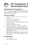
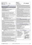
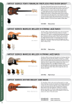
>> Bedienungsanleitung
Bad Bull 900 / Bad Bull 2000
WICHTIGE SICHERHEITSANWEISUNGEN!
Alle Tecamp Geräte sind für einen dauerhaften, sicheren Betrieb ausgelegt. Wenn Sie sich an die folgenden Anweisungen halten, können
Sie Schaden von sich, anderen und dem Gerät fernhalten.
1. Lesen Sie diese Sicherheitsanweisungen, bevor Sie das Gerät
benutzen.
2. Verwahren Sie diese Anweisungen an einem sicheren Ort, um
später immer wieder darauf zurückgreifen zu können.
3. Folgen Sie allen Warnhinweisen, um einen gesicherten Umgang
mit dem Gerät zu gewährleisten.
4. Folgen Sie allen Anweisungen, die in dieser Bedienungsanleitung
gemacht werden.
5. Betreiben Sie das Gerät nicht in der Nähe von Wasser oder in
Umgebungen mit starker Kondenswasserbildung, z.B. im Badezimmer, in der Nähe von Waschbecken, Waschmaschinen, feuchten Kellern, Swimming Pools usw.
6. Verdecken Sie nicht die Lüftungsschlitze. Bauen Sie das Gerät
so ein, wie der Hersteller es vorschreibt. Das Gerät sollte so
aufgestellt werden, dass immer eine ausreichende Luftzufuhr
gewährleistet ist. Zum Beispiel sollte das Gerät nicht im Bett,
auf einem Kissen oder anderen Oberflächen betrieben werden,
die die Lüftungsschlitze verdecken könnten, oder in einer festen
Installation derart eingebaut werden, dass die warme Luft nicht
mehr ungehindert abfließen kann.
7. Das Gerät sollte nicht in der Nähe von Wärmequellen betrieben
werden (z.B. Heizkörper, Wärmespeicher, Öfen, starke Lichtquellen, Leistungsverstärker etc.).
8. Vermeiden Sie starke Temperaturschwankungen.
9. Achten Sie darauf, dass das Gerät immer geerdet und das Netzkabel nicht beschädigt ist. Entfernen Sie nicht mit Gewalt den
Erdleiter des Netzsteckers. Bei einem Euro Stecker geschieht
die Erdung über die beiden Metallzungen an beiden Seiten des
Steckers. Die Erdung (der Schutzleiter) ist, wie der Name schon
sagt, zu Ihrem Schutz da. Falls der mitgelieferte Stecker nicht in
die örtliche Netzdose passt, lassen Sie den Stecker von einem
Elektriker (und nur von einem Elektriker!) gegen einen passenden
austauschen.
10.Schließen Sie den Verstärker nur an eine geerdete Steckdose mit
der korrekten Netzspannung an.
11.Netzkabel sollten so verlegt werden, dass man nicht über sie
stolpert, darauf herumtrampelt, oder dass sie womöglich von anderen spitzen oder schweren Gegenständen eingedrückt werden.
Netzkabel dürfen nicht geknickt werden – achten Sie besonders
auf einwandfreie Verlegung an der Stelle, wo das Kabel das Gerät
verlässt sowie nahe am Stecker.
12.Verwenden Sie nur Originalzubehör und/oder solches, das vom
Hersteller empfohlen wird.
13.Wird das verpackte Gerät mit einer Sackkarre transportiert, vermeiden Sie Verletzungen durch versehentliches Überkippen.
14.Ziehen Sie den Netzstecker bei Gewitter oder wenn es längere
Zeit nicht gebraucht wird.
15.Das Gerät sollte unbedingt von nur geschultem Personal repariert
werden, wenn: Das Netzkabel oder der Netzstecker beschädigt
wurde, Gegenstände oder Flüssigkeiten in das Innere gelangt
sind, das Gerät Regen ausgesetzt war, das Gerät offensichtlich
nicht richtig funktioniert oder plötzlich anders als gewohnt reagiert, das Gerät hingefallen oder das Gehäuse beschädigt ist.
Wartung: Der Anwender darf keine weiteren Wartungsarbeiten
an dem Gerät vornehmen als in der Bedienungsanleitung angegeben. Sonstige Wartungsarbeiten dürfen nur von geschultem
Personal durchgeführt werden.
16.Halten Sie das Gerät mit einem weichen, trockenen Lappen sauber. Wischen Sie es gelegentlich mit einem feuchten Tuch ab. Benutzen Sie keine anderen Reinigungs- oder Lösungsmittel, die die
Lackierung oder die Plastikteile angreifen könnten. Regelmäßige
Pflege und Überprüfung beschert Ihnen eine lange Lebensdauer
und höchste Zuverlässigkeit. Entkabeln sie das Gerät vor der Reinigung.
17.Stellen Sie den Verstärker niemals auf eine Unterlage, die das
Gewicht des Geräts nicht tragen kann.
18.Achten Sie immer darauf, dass die minimale Lastimpedanz der
angeschlossenen Lautsprecher nicht unterschritten wird.
19.Vermeiden Sie hohe Lautstärken über einen längeren Zeitraum.
Ihr Gehör kann massive Schäden davontragen – Hörverluste sind
fortschreitend und irreversibel!
VORSICHT: UM DIE GEFAHR VON STROMSCHLÄGEN ZU VERMEIDEN, ÖFFNEN SIE NICHT DAS GERÄT. ENTFERNEN SIE NIEMALS
DIE ERDUNG AM NETZKABEL. SCHLIEßEN SIE DAS GERÄT NUR AN
EINE ORDENTLICH GEERDETE STECKDOSE AN.
WARNUNG: UM DIE GEFAHR VON STROMSCHLÄGEN ZU VERRINGERN, SETZEN SIE DAS GERÄT KEINER FEUCHTIGKEIT ODER SOGAR
REGEN AUS.
VORSICHT: IM INNEREN BEFINDEN SICH KEINE TEILE, ZU DENEN
DER ANWENDER ZUGANG HABEN MUSS. REPARATUREN DÜRFEN NUR VON QUALIFIZIERTEM FACHPERSONAL DURCHGEFÜHRT
WERDEN. VORSICHT: DIESES GERÄT IST IN DER LAGE, SEHR HOHE
SCHALLDRÜCKE ZU ERZEUGEN. SETZEN SIE SICH NICHT LÄNGERE
ZEIT HOHEN LAUTSTÄRKEN AUS, DIES KANN ZU BLEIBENDEN GEHÖRSCHÄDIGUNGEN FÜHREN. TRAGEN SIE UNBEDINGT GEHÖRSCHUTZ, WENN DAS GERÄT MIT HOHER LAUTSTÄRKE BETRIEBEN
WIRD.
ACHTUNG STROMSCHLAGGEFAHR, NICHT ÖFFNEN
VORSICHT: UM DIE GEFAHR VON STROMSCHLÄGEN ZU VERMEIDEN, ENTFERNEN SIE KEINE ÄUSSEREN TEILE. DIESES GERÄT
ENTHÄLT KEINE TEILE, ZU DENEN DER ANWENDER ZUGANG HABEN MÜSSTE. LASSEN SIE ALLE SERVICE LEISTUNGEN VON AUSGEBILDETEM FACHPERSONAL BEI EINER AUTORISIERTEN SERVICE
WERKSTATT DURCHFÜHREN.
BESCHREIBUNG DER SYMBOLE:
GEFÄHRLICHE SPANNUNG: Dieses Dreieck mit dem Blitzsymbol
auf Ihrem Gerät macht Sie auf nicht isolierte „gefährliche Spannungen“ im Inneren des Gerätes aufmerksam,
stark genug um einen lebensbedrohlichen Stromschlag
abzugeben.
UNBEDINGT IN DER BEDIENUNGSANLEITUNG NACHSCHLAGEN:
Dieses Dreieck mit dem Ausrufezeichen auf Ihrem Gerät weist Sie auf wichtige Bedienungs- und Pflegeanweisungen in den Begleitpapieren hin.
WEEE: Entsorgung von gebrauchten elektrischen und
elektronischen Geräten (anzuwenden in den Ländern
der Europäischen Union und anderen europäischen
Ländern mit einem separaten Sammelsystem für diese Geräte). Das Symbol auf dem Produkt oder seiner
Verpackung weist darauf hin, dass dieses Produkt nicht als normaler
Haushaltsabfall zu behandeln ist, sondern an einer Annahmestelle
für das Recycling von elektrischen und elektronischen Geräten abgegeben werden muss. Durch Ihren Beitrag zum korrekten Entsorgen dieses Produkts schützen Sie die Umwelt und die Gesundheit
Ihrer Mitmenschen. Umwelt und Gesundheit werden durch falsches
Entsorgen gefährdet. Materialrecycling hilft den Verbrauch von Rohstoffen zu verringern. Weitere Informationen über das Recycling
dieses Produkts erhalten Sie von Ihrer Gemeinde, den kommunalen
Entsorgungsbetrieben oder dem Geschäft, in dem Sie das Produkt
gekauft haben.
>> Bad Bull
Treibt man die Vorstufe des Bad Bull in den Zerrbereich,
wird der Ton durch die Röhren milder in der Ansprache.
Er bekommt eine angenehme Wärme und der «GAIN»Regler beschneidet bei weiterem Aufdrehen die Pegelspitzen.
Die akribische Qualitätssicherung sorgt für absolute Betriebssicherheit. Der ausschließliche Einsatz hochwertigster Bauteile, die professionelle Verarbeitung und das
einzigartige Konzept setzen den Bad Bull an die Spitze
der Premium-Bassverstärker unserer Zeit.
Sie können sich freuen, es ist soweit – Sie halten gerade
die Bedienungsanleitung Ihres neuen TecAmp Bad Bull
in den Händen.
Der Bad Bull ist ein besonderer technischer Leckerbissen
mit einer Fülle an innovativen Besonderheiten. Durch
die Verbindung der edlen Röhrenvorstufe mit sechs Triodensystemen und der gewaltigen Power der digitalen
Monster-Endstufe setzt der Bad Bull neue Maßstäbe in
punkto Bassverstärkung.
Ob Eingangssektion, Klangreglung, Kompressor, Effektwege oder symmetrischer DI-Ausgang – alle Wege, die
das Bass-Signal nimmt, sind von höchster Qualität. Die
zuschaltbare 6V6 Endstufenpentode sitzt zwischen Vorund Endstufe. Sie erweitert fein dosierbar den Sound
mit typischer Endstufenröhren-Verzerrung. Der daraus
entstehende Klang wird von der einzigartigen Dynamik
der digitalen Endstufe mit souveräner Leichtigkeit ohne
Einbußen auf höchste Pegel-Niveaus geliftet.
!
EG-Konformitätserklärung für das Produkt/Type
Bad Bull Bassamp
Wir erklären in alleiniger Verantwortung als Hersteller,
dass dieses Produkt unter Beachtung der Betriebsbedingungen und Einsatzumgebung laut Bedienungsanleitung
mit den folgenden Normen oder normativen Dokumenten
übereinstimmt:
EN 61000-3-2, EN 61000-3-3, EN 55013, EN 55020,
EN 55022, EN 60065
gemäß den Bestimmungen der Richtlinien 89/336/EWG
und 73/23/EWG.
3
>> Front Panel Bad Bull
1
3
4
Gain
Sub
Hi
5
Gain
6
Bass
Sub
7
LoMid
Bass
8
Mid
LoMid
9
HiMid
High
Mid
ThresholdHigh
HiMid
Ratio
11
12a 12
Threshold
Power Tube
Ratio
O
IO
O
Lo
O
IO
IO O
O IO
IO
O
O IO
IO
O
O IO
IO
O
O IO
IO
O
O IO
IO O
O
IO
IO O
O
3a
10
1 HI
Stecken Sie den Klinkenstecker Ihres abgeschirmten Instrumentenkabels in die «HI»-Buchse, wenn Ihr Instrument
mit passiven Tonabnehmern ausgestattet ist, oder über
relativ wenig Ausgangsleistung verfügt.
Aktive Instrumente, die an dieser Buchse angeschlossen
werden, bringen den Bad Bull entsprechend früher in die
Röhrensättigung.
der Röhrenvorverstärker mit leichter Kompression und
bei weiterem Aufdrehen mit weichen Verzerrungen. Aufgrund dieser Eigenschaften wurde auf eine Clip-LED verzichtet, da ein angezerrter Basssound mit harmonischen
Obertönen oftmals durchaus willkommen ist.
Stellen Sie den «VOLUME»-Regler Ihres Instruments
nicht zu gering ein, da sich sonst Störungen auf dem Signalweg zum Bad Bull stärker bemerkbar machen.
2 LO
3a Magisches Auge
Wenn Ihr Bass über eine aktive Elektronik verfügt, oder
prinzipiell eine sehr hohe Ausgangsleistung hat, ist es
ratsam, den «LO»-Eingang zu benutzen. Hier wird der
Eingang um 10 dB bedämpft. Eine Bedämpfung im Eingang ermöglicht es, mit dem «GAIN»-Regler (#3) feinere
Abstimmungen vornehmen zu können, da sich der Regelweg dadurch ändert – Sie können den «GAIN»-Regler nun
weiter aufdrehen.
Das Magische Auge (eine EM 84 Anzeigenröhre), das
sich unter dem «GAIN»-Regler befindet, zeigt die Aussteuerung der Eingangsstufe des Bad Bull an. Wenn die
beiden blaugrünen Leuchtbalken dieser Anzeigenröhre in
der Mitte zusammentreffen, ist die maximale cleane Aussteuerung erreicht. Wird der «GAIN»-Regler jetzt weiter
aufgedreht, kommen die harmonischen Röhrenverzerrungen der Vorstufe hinzu.
3 GAIN
4-9 Klangregelung
Stellen Sie den «GAIN»-Regler anfänglich senkrecht auf
Position 12 Uhr. Bei weit aufgedrehtem «GAIN» reagiert
Das Schaltungskonzept der Klangregelung wird mit Induktivitäten realisiert. Dieser sechs-Band Spulen-Equalizer
4
On
On
Volume
2
MasterPower Tube Break
14
15
Master
Break
Hi
On
Lo
13a 13
IO
O IO
IO O
On
O
IO
IO O
Volume Volume
O
IO
O
O IO
IO
O
IO
Volume
IO
O
12b
IO
13b
3a
7 MID
überzeugt durch feinste Ansprache und herausragendem
Frequenzgang bei gleichzeitigem hohem Rauschabstand.
Der «MID»-Regler bestimmt die Durchsetzungskraft
im Bandgefüge bei Frequenzen um 800 Hz. Besonders
geeignet, um den Frettless singen zu lassen, oder gewünschte Rückkopplung bei weit aufgedrehtem «GAIN»
zu fördern.
4 SUB
Der «SUB«-Regler nimmt Einfluss auf den sehr tiefen
Bassbereich. Seine Center-Frequenz liegt bei 30 Hz. Hier
sollte man wirklich vorsichtig sein, wenn Boxen zum Einsatz kommen, die der Belastung des Bad Bull nicht standhalten. Ein einziger Ton kann hier sofort zu Beschädigungen an den angeschlossenen Lautsprechern führen.
8 HiMID
Der «Hi MID»-Regler übernimmt den oberen Mitteltonbereich bei Frequenzen um 3 KHz. Dies hebt beim
Aufdrehen (speziell beim Plektrum-Spiel) den typischen
Anschlag-Attack hervor.
5 BASS
Der «BASS»-Regler regelt die Anhebung bzw. Absenkung
der Frequenzen um 80 Hz. Er bringt den mächtigen Bassdruck, der in dieser Klarheit nur von einer Röhrenvorstufe
erzeugt werden kann.
9 HIGH
Der «HIGH»-Regler regelt die Frequenzen bei 10 KHz.
Hier können die obersten Brillanzen bedämpft oder angehoben werden.
6 LoMID
10 Bull Eyes
Der «Lo MID»-Regler nimmt Einfluss auf die Durchsetzungskraft des Bass-Sounds im Tiefmittenbereich bei
Frequenzen um 200 Hz. Sehr gut geeignet, um auch problematische Raumresonanzen in den Griff zu bekommen.
Die beiden Augen des Bad Bull-Logos auf der Frontseite leuchten rot, wenn der Verstärker eingeschaltet ist.
Wenn das mitgelieferte Netzkabel an der auf der Rück-
5
>> Front Panel Bad Bull
1
3
4
Gain
Sub
Hi
5
Gain
6
Bass
Sub
7
LoMid
Bass
Mid
8
LoMid
9
HiMid
High
Mid
ThresholdHigh
HiMid
Ratio
11
12a 12
Threshold
Power Tube
Ratio
O
IO
O
Lo
O
IO
IO O
O IO
IO
O
O IO
IO
O
O IO
IO
O
O IO
IO
O
O IO
IO O
O
IO
IO O
O
3a
10
Der «THRESHOLD»-Regler ist in Verbindung mit dem
«RATIO»-Regler (#12) die Reglereinheit, um den eingebauten Röhrenkompressor abzustimmen. Ist der Regler
zugedreht (gegen den Uhrzeigersinn), wird kein Einfluss
auf das Signal genommen. Beim Aufdrehen werden die
Pegelspitzen des Bass-Signals oberhalb der durch den
«RATIO»-Regler (#12) festgelegten Größe komprimiert.
tes justierbar. Während der Ratio-Regler (#12) das Verhältnis der Kompression zum Signalpegel einstellt, regelt der
Volume-Regler die Gesamtlautstärke des Compressor-Effektes. Somit ist ein, zuvor in der Lautstärke eingestellter,
Compressor-Effekt via Fußschalter abrufbar.
Der Schalter (#12a) aktiviert den Compressor. Der Schalter korrespondiert mit der Footswitch-Buchse (#26) über
die, mittels des optional erhältlichen Fußschalters FS
BAD BULL, die Funktion fernbedienbar ist. Ist der Fußschalter an der Footswitch-Buchse angeschlossen, hat
dieser Vorrang, d. h. der Schalter (#12a) und die LED Anzeige ist nicht aktiv. Der Schaltzustand ist dann über die
LED Anzeige am Fußschalter FS BAD BULL zu sehen.
12 RATIO
13 POWER TUBE
Mit dem «RATIO»-Regler wird das Verhältnis der Kompression zum Signalpegel eingestellt. Ist der Regler zugedreht (gegen den Uhrzeigersinn), wird kein Einfluss
auf das Signal genommen. Je weiter der «RATIO»-Regler
aufgedreht wird, desto stärker kann das Signal mit dem
«THRESHOLD»-Regler (#11) bearbeitet werden.
Mit dem Regler (12b) ist der Pegel des Compressor-Effek-
Hier kann die eingebaute Endstufenröhre vom Typ 6V6
dem Bass-Signal stufenlos beigemischt werden. Ist der
«POWER TUBE»-Regler zugedreht, wird die Röhre nicht
überfahren und arbeitet clean, fügt aber dem Sound ihren Charakter bei. Dreht man den «POWER TUBE»-Regler
auf, wird die 6V6 Röhre in die Sättigung gefahren, was die
harmonischen Verzerrungen fördert. Gleichzeitig wird das
seite befindlichen Netzbuchse (#16b) eingesteckt und der
danebenliegende Netzschalter (#16a) eingeschaltet ist,
leuchten die Augen des Bad Bull rot – unabhängig von
weiteren Schalterstellungen.
11 THRESHOLD
6
On
On
Volume
2
MasterPower Tube Break
14
15
Master
Break
Hi
On
Lo
13a 13
IO
O IO
IO O
On
O
IO
IO O
Volume Volume
O
IO
O
O IO
IO
O
IO
Volume
IO
O
12b
IO
13b
3a
zur Endstufe gelangt, regelt das Volume-Poti die Lautstärke des bearbeiteten Signals. Somit ist ein, zuvor in der
Lautstärke eingestelltes Signal mit POWER TUBE-Sound
via Fußschalter abrufbar.
unbearbeitete Bass-Signal ausgeblendet und der Endstufensound dominiert bei Vollanschlag das komplette Signal.
Durch Ziehen des Power-Tube-Reglers kann bei Bedarf die
6V6 Röhre umgangen werden, um ein Bass Sound ohne
Röhren-Endstufenklang bereit zu stellen.
Die auf der Rückseite des Bad Bull befindliche «POWER
TUBE SPEAKER OUT»-Buchse (#20) dient zum Anschluss
einer Lautsprecherbox. Es stehen etwa 4 Watt Ausgangsleistung zur Verfügung, die zu 100% von der 6V6 Röhre
kommen. Die Lautstärke dieses Ausgangs übernimmt der
«POWER TUBE»-Regler (#13). Der Schalter (#13a) aktiviert
die 6V6 POWER TUBE. Der Schalter korrespondiert mit
der Footswitch-Buchse (#26) über der, mittels des optional erhältlichen Fußschalters FS BAD BULL, die Funktion
fernbedienbar ist.
Ist der Fußschalter an der Footswitch-Buchse angeschlossen, hat dieser Vorrang d.h. der Schalter (#13a) und die
LED Anzeige ist nicht aktiv. Der Schaltzustand wird dann
über die LED Anzeige am Fußschalter FS BAD BULL angezeigt. Mit dem Volume-Regler (#13b) ist der Pegel der
POWER TUBE einstellbar. Während der POWER TUBERegler (#13) die Sättigung bestimmt, mit der das Signal
14 MASTER
Mit diesem Regler wird die Ausgangslautstärke des Verstärkers eingestellt. Er hat gleichzeitig Einfluss auf den
Pegel des «LINE OUT» (#25) auf der Rückseite.
15 BREAK
Der «BREAK»-Schalter sollte nach dem Einschalten des
Bad Bull auf der Rückseite (#16a) in Stellung «BREAK»
stehen. Dadurch werden die Röhren auf Betriebsbereitschaft geheizt. In dieser Stellung wird das Instrumentensignal nicht an die Ausgänge weiter geleitet.
Allerdings gelangt das Instrumentensignal weiterhin
an die «TUNER»-Buchse (#24), so dass geräuschlos gestimmt werden kann. Sie müssen dafür nicht extra den
Lautstärkeregler herunter drehen.
Auch bei einem Instrumentenwechsel bietet sich dieser
Schalter an, weil dann lästige Kontaktgeräusche vom
7
>> Front Panel Bad Bull
HiMid
9
11
High
Threshold
>> Rear Panel Bad Bull
12a 12
13a 13
Ratio
Power Tube
On
14
15
Master
Break
17a
HIGH VOLTAGE! CAUTION: TO PREVENT THE RISK OF FIRE
AND SHOCK HAZARD DON’T EXPOSE THIS APPLIANCE TO
MOISTURE OR RAIN. DO NOT OPEN CASE.
NO USER SERVICEABLE PARTS INSIDE. REFER SERVICING
TO QUALIFIED SERVICE PERSONNEL.
230 V/AC
FUSE 400W: T5A
FUSE 600W: T6,3A
BRIDGED MODE / MIN. LOAD 4 OHMS
BRIDGE
VOLUME
LO PASS
CHANNEL B / MIN. LO
HI PASS
FREQ.
CH
!
On
CHANNEL A / MIN. LOAD 2 OHMS
ON
OFF
0
-10
CH
B
A
ON
OFF
40 Hz
ON
OFF
20 KHz
Made in Germany
IO
O
IO
IO
O
IO
TR
U
TR
U
TR
U
IO
USE ONLY WITH A 250V FUSE
SPEAKER OUTPUT
12b
13b
3a
16a
16b 16c
17
sorgung entstehen. Wenn die Sicherung anspricht und
durchbrennt, darf sie nur durch eine gleichen Typs und
Werts ersetzt werden. Im Sicherungsfach (#16c) befindet
sich eine Ersatzsicherung. Sollte die Netzsicherung nach
Austausch sofort wieder durchbrennen, liegt ein ernsthafter Schaden vor, der nur durch einen autorisierten
Service-Techniker behoben werden sollte.
16a POWER
Klinkenstecker unterbunden werden.
Der «BREAK»-Schalter unterbricht auch den symmetrischen «XLR DI»-Ausgang (#23c). Dabei spielt es keine
Rolle, in welcher Stellung sich der DI «PRE/POST»-Schalter (#23b) oder der DI «Phase/Reversed»-Schalter (#23a)
befindet.
In Spielpausen sollte der Verstärker nicht ausgeschaltet, sondern der «BREAK»-Betrieb eingestellt werden.
Die lüftergekühlte Digitalendstufe wird dann im Stand
By-Betrieb, falls notwendig, heruntergekühlt. Wird der
«BREAK»-Schalter nach oben gestellt, nimmt der Bad
Bull seinen Betrieb auf und lässt an alle vorhandenen
Ausgänge Signal fließen.
Mit dem »POWER«-Schalter wird der Bad Bull eingeschaltet. Wenn das Gerät eingeschaltet ist (am Schalter
muss die Oberseite herunter gedrückt sein), leuchten zur
Kontrolle die auf der Frontseite befindlichen Augen des
Bad Bull Logos (#10) rot auf und nach wenigen Sekunden zeigen auch die beiden Magischen Augen (#3b und
#14b) ihre Betriebsbereitschaft.
17 SPEAKER BRIDGED MODE
Beim Bad Bull stehen sechs Speakon-Anschlüsse vom
Typ NL4 MP zur Verfügung. Die Anschlüsse sind mit 1- =
minus und 1+ = plus belegt. Beim Betrieb im «BRIDGED
MODE» ist darauf zu achten, dass die Gesamtimpedanz
von 4 Ohm nicht unterschritten wird! Drücken Sie den
Schalter (#17a), bis er in die «ON»Position einrastet. Der
«BRIDGED»-Kanal ist nun betriebsbereit und die Vol.
Potis (#18a und #18e) von «CHANNEL A» (#18A) und
«CHANNEL B» (#18B) sind außer Betrieb gesetzt, Dieser
Ausgang ist perfekt geeignet um z. B. die Boxen L610
oder die Bad Cab zu betreiben.
An diesen Buchsen steht die volle Ausgangsleistung von
Watt an 4 Ohm zur Verfügung. In diesem Fall dürfen die
16b/c Netzkabel/Netzanschluss
Ihr Bad Bull besitzt einen Anschluss für ein Kaltgerätekabel (#16b), an das Sie das mitgelieferte Netzkabel anschließen. Stecken Sie den weiblichen Kaltgerätestecker
fest in die Netzbuchse. Bei dem Netzkabel muss es sich
auf jeden Fall um ein dreipoliges, geerdetes Kabel mit
Schukostecker handeln. Versuchen Sie bitte niemals,
die Masseverbindung (Erdung) am Schukostecker
durch Abkleben oder ähnliches zu unterbrechen,
wenn Sie eine Brummschleife haben.
Die im Sicherungsfach (#16c) untergebrachte Sicherung
schützt das Gerät vor Schäden, die durch Überlastung
oder Beeinträchtigungen bzw. Fehler in der Netzver-
8
9
IK
IK
O
TR
U
IK
IO
TR
U
IK
O
O
Volume
IK
Volume
NE
O
NE
IO
NE
O
NE
IO
NE
O
>> Rear Panel Bad Bull
!
17a
18a 18b
18c
21a
18d 18e
HIGH VOLTAGE! CAUTION: TO PREVENT THE RISK OF FIRE
CHANNEL A / MIN. LOAD 2 OHMS
CHANNEL B / MIN. LOAD 2 OHMS
BRIDGED MODE / MIN. LOAD 4 OHMS
ISK OF FIRE
CHANNEL A
CHANNEL A / MIN. LOAD 2 OHMS
CHANNEL B / MIN. LOAD 2 OHMS
BRIDGED
MODE
SPEAKER OUT
AND SHOCK HAZARD DON’T EXPOSE
THIS APPLIANCE
TO / MIN. LOAD 4 OHMS
PLIANCE TO
VOLUME LO PASS
BRIDGE
HI PASS VOLUME
FREQ.
MOISTURE OR RAIN. DO NOT OPEN CASE.
VOLUME LO PASS
BRIDGE
HI PASS VOLUME
FREQ.
NO USER SERVICEABLE PARTS INSIDE. REFER SERVICING
SERVICING
CH
CH
TO QUALIFIED SERVICE PERSONNEL.
CH
CH
230 V/AC
FUSE 400W: T5A
ON
ON
ON
FUSE 600W: T6,3A
ON
ON
ON
0
40 Hz
20 KHz
OFF
OFF
OFF -10
-10
0
0
40 Hz
20 KHz
OFF
OFF
OFF -10
-10
0
POWER
TUBE
Made in Germany
SEND
MIX
-10 dB
HIGH
PASS
DRY
WET
POWER
TUBE
DRY
ON
OFF
WET
USE ONLY WITH A 250V FUSE
17
18A
SPEAKER OUTPUT
18B
CHANNEL B
POWER
AMP
IN
19
& #18e), die es erlauben, je Kanal unterschiedliche Pegel der angeschlossenen Boxen einzustellen. Stellen sie
sicher, dass sich der «BRIDGED»-Schalter (#17a) in der
«OFF»-Position befindet, um die Kanäle «A» und «B» in
der Lautstärke zu regeln.
Außerdem besteht die Möglichkeit, durch Drücken des
Schalters (#18b) in die «ON»-Position das eingebaute
«LO PASS Crossover» zu aktivieren. Der «CHANNEL A»
kann dadurch unter anderem zum Ansteuern eines Subwoofers in einem Biamp-System genutzt werden. Mit
den Frequ. Regler (#18c) kann die Cut-Frequenz stufenlos
zwischen 20 KHz. und 40 Hz. frei gewählt werden.
Der Kanal «B» (#18B) bietet die Möglichkeit durch Drücken des Schalters (#18d) in die «ON»-Position das
eingebaute «HI PASS Crossover» zu aktivieren. Der
Kanal «B» kann dadurch unter anderem zum Ansteuern
eines Mittelhochtöners in einem Biampsystem genutzt
werden. Mit dem «FREQ.»-Regler (#18c) kann die CutFrequenz stufenlos zwischen 20 KHz. und 40 Hz. frei
gewählt werden. Die Crossover-Funktion kann für beide
Kanäle separat aktiviert werden.
Achten Sie beim Anschluss von Lautsprecherboxen auf
Buchsenpaare (#18A) und (#18B) nicht benutzt werden.
TIPP: Achten Sie beim Anschluss von Lautsprecherboxen
auf ausreichenden Querschnitt des Kabels (wir empfehlen min. 2 x 2,5 mm2). Um den Bad Bull an die jeweilige
Box anzuschließen sollten Kabel mit Speakon®-Steckern
vom Typ NL2FC (2-polige Ausführung) oder NL4FC (4-polige Ausführung) benutzt werden. Bei beiden SteckerAusführungen muss der Pluspol des Lautsprecherkabels
an die mit 1+ gekennzeichnete Klemme des Steckers und
der Minuspol des Kabels an die mit 1- gekennzeichnete
Klemme angeschlossen werden.
18 SPEAKER CH A - CH B
Die beiden Buchsen des «CHANNEL A» (#18A) können
mit 2 Ohm belastet werden. Die Ausgangsleistung am
«CHANNEL A» beträgt 450 Watt an 2 Ohm. «CHANNEL
B» (#18B) besitzt die gleichen Anschlussmöglichkeiten wie
der «CHANNEL A» (#18A) und kann gleichzeitig mit diesem betrieben werden. Es können also insgesamt 4 Boxen
mit je 4 Ohm gleichzeitig am Bad Bull 900 angeschlossen
werden.
Beide Kanäle besitzen separate Lautstärkenregler (#18a
10
ON
OFF
ON
OFF
HIGH
PASS
IN
PHASE
ON
OFF
REVERSED
180°
SEND
PRE
POST
23a 23b
TUNER
FOOTSWITCH
PRE
IN PHASE
REVERSED
180°
24
26
TUNER
FOOTSWITCH
POST
RING =
COMPRESSOR
RING =
COMPRESSOR
CHANNEL B
RETURN
SEND
RETURN
LOOP 1
SPEAKER OUTPUT
SENDSEND
-10 dB
22a
TR
U
NE
NE
NE
NE
NE
NE
NE
NE
TR
U
IK
TR
U
IK
NE
TR
U
IK
TR
U
IK
NE
TR
U
IK
TR
U
IK
NE
TR
U
IK
TR
U
IK
IK
IK
NE
TR
U
IK
TR
U
IK
TR
U
SPEAKER OUT
MIX
21c 21d 21e
B
A
B
A
!
CHANNEL A
21b
SEND
RETURN
RETURN
LOOP 1
LOOP 2
POWER
AMP
IN
LINE OUT
LOOP 2
21
LINE OUT
TIP =
POWERTUBE
DI OUT
DI OUT
20
TIP =
POWERTUBE
22b
23c
25
der Frontseite.
ausreichenden Querschnitt des Kabels (wir empfehlen
min. 2 x 2,5 mm2). Hochwertige Lautsprecherkabel sind
optional erhältlich.
21 LOOP 1
Dieser parallele Effekteinschleifweg dient zum Anschluss
eines oder mehrerer Effektgeräte. Es kann zwischen Fullrange und der Bearbeitung des Signals oberhalb von 360
Hz («HIGH PASS» #21e), z.B. bei Chorus oder Octaver, gewählt werden. Verbinden Sie die Buchse «SEND» (#21d)
mit dem Eingang und die Buchse «RETURN» (#21b) mit
dem Ausgang Ihres Effektgerätes. Möchten Sie das
Tiefbass-Signal ohne Effekt belegen, so drücken Sie den
«HIGH PASS»-Schalter (#21e).
Sollte das angeschlossene Effektgerät mit dem Pegel
der «SEND»-Buchse (#21d) übersteuert sein, kann das
Signal mit dem «SEND -10dB»-Schalter (#21c) abgesenkt
werden. Gleichzeitig wird durch die Aktivierung dieses
Schalters der Pegel des Returnsignals um 10 dB angehoben, um den Lautstärkeverlust auszugleichen. Mit
dem «MIX»-Potentiometer (#21a) kann das Effektsignal
dem Bassignal stufenlos von «DRY» (ohne Effekt) bis
«WET» (100% Effekt, seriell) beigemischt werden. Die
«RETURN»-Buchse (#21b) kann außerdem genutzt wer-
19 POWER AMP IN
Über die Buchsen «POWER AMP IN CHANNEL A» (#19a)
und «CHANNEL B» (#19b) kann jeder Kanal des Bad Bull
separat als Endstufe genutzt werden.
So ist es zum Beispiel möglich, Kanal «A» mit einer Bassbox zu verkabeln und über den Bad Bull diesen Kanal mit
dem Instrument zu speisen, und gleichzeitig den Kanal «B»
als Endstufe der PA zur Verfügung stellen. Die «BRIDGED
MODE»-Funktion steht dann logischerweise nicht zur Verfügung und der «BRIDGE»-Schalter (#17a) muss sich in der
«OFF»-Position befinden.
20 POWER TUBE
Die «POWER TUBE SPEAKER OUT»-Buchse (#20) dient
zum Anschluss einer Lautsprecherbox zum Üben. Es stehen etwa 4 Watt Ausgangsleistung zur Verfügung, die zu
100% von der 6V6 Röhre kommen. Die Lautstärke dieses
Ausgangs übernimmt der Power Tube Regler (#13) auf
11
>> Rear Panel Bad Bull
!
17a
18a 18b
18c
21a
18d 18e
HIGH VOLTAGE! CAUTION: TO PREVENT THE RISK OF FIRE
CHANNEL A / MIN. LOAD 2 OHMS
CHANNEL B / MIN. LOAD 2 OHMS
BRIDGED MODE / MIN. LOAD 4 OHMS
ISK OF FIRE
CHANNEL A
CHANNEL A / MIN. LOAD 2 OHMS
CHANNEL B / MIN. LOAD 2 OHMS
BRIDGED
MODE
SPEAKER OUT
AND SHOCK HAZARD DON’T EXPOSE
THIS APPLIANCE
TO / MIN. LOAD 4 OHMS
PLIANCE TO
VOLUME LO PASS
BRIDGE
HI PASS VOLUME
FREQ.
MOISTURE OR RAIN. DO NOT OPEN CASE.
VOLUME LO PASS
BRIDGE
HI PASS VOLUME
FREQ.
NO USER SERVICEABLE PARTS INSIDE. REFER SERVICING
SERVICING
CH
CH
TO QUALIFIED SERVICE PERSONNEL.
CH
CH
230 V/AC
FUSE 400W: T5A
ON
ON
ON
FUSE 600W: T6,3A
ON
ON
ON
0
40 Hz
20 KHz
OFF
OFF
OFF -10
-10
0
0
40 Hz
20 KHz
OFF
OFF
OFF -10
-10
0
POWER
TUBE
Made in Germany
SEND
MIX
-10 dB
DRY
WET
POWER
TUBE
DRY
ON
OFF
USE ONLY WITH A 250V FUSE
17
SPEAKER OUTPUT
18A
18B
den, um externe Audioquellen (z.B. CD Player), oder einen zweiten Bass anzuschließen, bzw. um die Endstufe
des Bad Bull separat zu betreiben.
Achtung! Wenn kein Effektgerät am «LOOP 1» angeschlossen ist, muss sich der Schalter 21e unbedingt in «OFF»-Position befinden, um den vollen
Frequenzbereich zu übertragen.
CHANNEL B
POWER
AMP
IN
19
23 DI OUT
Der Bad Bull liefert ein trafosymmetrisches Vorstufensignal zum Anschluss an die PA, für Aufnahmezwecke oder
zum Ansteuern eines weiteren Verstärkers mit symmetrischen Eingängen. Dies macht die Verwendung einer
zusätzlichen DI-Box überflüssig. Durch die Verwendung
hochwertiger Bauteile ist die Qualität des «DI»-Ausgangs
auch besonders für Aufnahmen im Tonstudio geeignet.
Der Anschluss erfolgt über die XLR-Buchse (#23c). Das
Signal kann vor oder hinter der Vorstufe abgenommen
werden, abhängig von der Schalterstellung des «PRE/
POST»-Schalters (#23b). Dieser Schalter bestimmt, ob
das «DI»-Signal direkt am Eingang nach der 6V6 Röhrenstufe des Bad Bull abgenommen wird («PRE»), oder ob es
die komplette Vorstufe durchläuft («POST»).
Eine Besonderheit stellt hier die «POST»-Stellung des
Schalters #23b dar. Hier wird das Bass-Signal sogar nach
der 6V6 Power Tube Endstufenpentode abgegriffen, was
zur Folge hat, dass man in der Post Stellung den authentischen Klang des Bad Bull, der auch an die Boxen fließt,
an die PA weiterleitet. Also auch, wenn gewünscht, mit
22 LOOP 2
An diesem seriellen Effektweg kann ein Effektgerät eingeschliffen werden. Das gesamte Signal wird hier durch
das Effektgerät geleitet. Verbinden Sie dazu die «SEND»Buchse (#22a) mit dem Eingang und die «RETURN»-Buchse (#22b) mit dem Ausgang Ihres Effektgerätes. Beide
Effektwege können gleichzeitig betrieben werden!
Achten Sie beim Verkabeln auf qualitativ hochwertige
Kabel. Falls bei Betrieb eines Effektgerätes kratzende
Verzerrungen auftreten, so sind entweder die Batterien
des Effektgerätes verbraucht oder der Pegel des Verstärkers ist für das angeschlossene Effektgerät zu hoch.
Benutzen Sie in diesem Fall besser den «LOOP 1» (#21),
unter Verwendung des «SEND -10dB»-Schalters (#21c).
12
SENDSEND
-10 dB
WET
ON
OFF
ON
OFF
HIGH
PASS
IN
PHASE
ON
OFF
REVERSED
180°
SEND
PRE
POST
23a 23b
TUNER
FOOTSWITCH
PRE
IN PHASE
REVERSED
180°
24
26
TUNER
FOOTSWITCH
POST
RING =
COMPRESSOR
RING =
COMPRESSOR
CHANNEL B
RETURN
SEND
RETURN
LOOP 1
SPEAKER OUTPUT
HIGH
PASS
22a
TR
U
NE
NE
NE
NE
NE
NE
NE
NE
TR
U
IK
TR
U
IK
NE
TR
U
IK
TR
U
IK
NE
TR
U
IK
TR
U
IK
NE
TR
U
IK
TR
U
IK
IK
IK
NE
TR
U
IK
TR
U
IK
TR
U
SPEAKER OUT
MIX
21c 21d 21e
B
A
B
A
!
CHANNEL A
21b
SEND
RETURN
RETURN
LOOP 1
LOOP 2
POWER
AMP
IN
LOOP 2
21
22b
einer Pentodensättigung auf dem «DI OUT».
Der Bad Bull verfügt über eine extrem starke Endstufe.
Gerade auf großen Bühnen kann es dadurch, dass die
Bassanlage und die PA-Boxen nicht auf gleicher Höhe
stehen (Laufzeitunterschiede), zu einer Phasenverschiebung mit dem PA-Signal kommen. Dann löschen sich
diese beiden Signale, die sich ja addieren sollen, gegenseitig aus, was unter anderem zu einem drastischen
Druckverlust des Bass-Signals führt.
Durch Aktivieren des Phasen-Schalters (#23a) kann das DISignal des Bad Bull in der Phasenlage um 180° gedreht
werden, um dieser Phasenauslöschung entgegenzuwirken.
TIP =
POWERTUBE
LINE OUT
TIP =
POWERTUBE
DI OUT
DI OUT
20
LINE OUT
23c
25
ding zu benutzen. Der «MASTER»-Regler (#14) legt die
Lautstärke fest.
26 FOOTSWITCH
An diese 6,3 mm Stereo-Klinkenbuchse wird der optional erhältliche Fußschalter FS BAD BULL angeschlossen.
Stecken Sie das mitgelieferte Stereo-Klinkenkabel in die
»FS« Buchse des BAD BULL und verbinden Sie das andere Ende des Kabels mit dem Fußschalter. Mit dem FS
BAD BULL können der »Compressor« und die »Power
Tube«-Funktion fernbedient werden.
24 TUNER
Diese Buchse dient zum Anschluss eines Stimmgerätes. Sie ist immer aktiv, auch wenn sich der Bad Bull in
«BREAK»-Stellung (#15) befindet.
25 LINE OUT
An dieser Buchse kann eine zusätzliche Endstufe angeschlossen werden. Außerdem besteht die Möglichkeit,
das Bass-Signal auf die P.A. zu geben oder zum Recor-
13
>> Specs Bad Bull
>> Specifications Bad Bull
Vorstufe: Vollröhre 2 x ECC81 und 1 x ECC83
optische Kontrolle: 2 x magisches Auge
Ausgangsleistung: 1 x 1.500 W (8 Ohm), 1 x 2.000 W (4 Ohm)
Ausgangsleistung: 2 x 450 W (2 Ohm), 900 W (4 Ohm bridged mode)
Röhrentreiberendstufe: 6V6 zuschaltbar
Bad Bull 2000
Bad Bull 900
x
x
x
x
x
–
–
x
x
x
–
x
2.500 W
x
1.000 W
x
x
x
Kompressor: Röhre mit Ratio-, Threshold und Pegel-Regler
zuschaltbar
x
x
Effektweg 1: seriell, regelbar; mit schaltbarem Hochpassfilter
Effektweg 2: parallel
x
x
x
x
DI Ausgang: trafosymmetriert, pre/post schaltbar mit
180° Phasenumschaltung
x
x
Spannungsversorgung: 115/230 V/AC umschaltbar
Eingänge: Input High; Input Low; Effect Return; Power Amp In
x
x
Endstufe: Class D mit separater Lautstärkenregelung
für CH-A & CH-B mit Weiche
Leistungsaufnahme:
Schaltnetzteil: digital
Klangregelung: 6-Band Spulen EQ
Ausgänge Neutrik Speakon®, Effect Send, Tuner, Powertube,
Line Out
Kühlung: temperaturgesteuerter Lüfter
Abmessungen: B x H x T (cm)
Gewicht:
optionales Zubehör: Cover, Footswitch für »Compressor« und »Power Tube«
14
x
x
x
x
x
x
60 x 23 x 27
60 x 23 x 27
11 kg
x
10 kg
x
TOP VIEW
AUFSICHT
POWERAMP
V1
V2
V3
V4
FRONTPANEL BAD BULL
Tube Task Chart
Types of Tubes:
V1:ECC81
12AT7
V3:ECC83
12AX7
V2:ECC81
12AT7
V4:6V6
15
Alter Bahnhofsweg 5 · D-35745 Herborn Fon +49 (0) 2777-6391 · e-Mail: [email protected] · www.tecamp.de
>> Manual
Bad Bull 900/2000
>> Bad Bull
Important Safety Instructions
The apparatus shall not be exposed to dripping or splashing and that
no objects with liquids, such as vases, shall be placed on the apparatus. The MAINS plug is used as the disconnect device, the disconnect
device shall remain readily operable.
Warning: the user shall not place this apparatus in the area during
the operation so that the mains switch can be easily accessible.
1. Read these instructions before operating this apparatus.
2. Keep these instructions for future reference.
3. Heed all warnings to ensure safe operation.
4. Follow all instructions provided in this document.
5. Do not use this apparatus near water or in locations where condensation may occur.
6. Clean only with dry cloth. Do not use aerosol or liquid cleaners.
Unplug this apparatus before cleaning.
7. Do not block any of the ventilation openings. Install in accordance
with the manufacturer’s instructions.
8. Do not install near any heat sources such as radiators, heat
registers, stoves, or other apparatus (including amplifiers) that
produce heat.
9. Do not defeat the safety purpose of the polarized or groundingtype plug. A polarized plug has two blades with one wider than
the other. A grounding type plug has two blades and a third
grounding prong. The wide blade or the third prong is provided
for your safety. If the provided plug does not into your outlet,
consult an electrician for replacement of the obsolete outlet.
10.Protect the power cord from being walked on or pinched particularly at plug, convenience receptacles, and the point where they
exit from the apparatus.
11.Only use attachments/accessories specified by the manufacturer.
12.Use only with a cart, stand, tripod, bracket, or table specified
by the manufacturer, or sold with the apparatus. When a cart is
used, use caution when moving the cart/apparatus combination
to avoid injury from tipover.
13.When a cart is used, use caution when moving the cart/apparatus combination to avoid injury from tipover.
14.Unplug this apparatus during lighting storms or when unused for
long periods of time.
15.Refer all servicing to qualified service personnel. Servicing is required when the apparatus has been damaged in any way, such
as power-supply cord or plug is damaged, liquid has been spilled
or objects have fallen into the apparatus, the apparatus has been
exposed to rain or moisture, does not operate normally, or has
been dropped.
CAUTION: Use of controls or adjustments or performance of procedures other than those may result in hazardous radiation exposure.
WARNING: To reduce the risk of FIRE or electric shock, do
not expose this apparatus to rain or moisture.
CAUTION: RISK OF ELECTRIC SHOCK DO NOT OPEN
CAUTION: TO REDUCE THE RISK OF ELECTRIC SHOCK, DO NOT
REMOVE COVER (OR BACK) NO USER SERVICEABLE PARTS INSIDE
REFER SERVICING TO QUALIFIED PERSONNEL
The lightning flash with arrowhead symbol, within an
equilateral triangle, is intended to alert the user to the
presence of uninsulated “dangerous voltage” within
the product’ s enclosure that may be of suficient magnitude to constitute a risk of electric shock to persons.
The exclamation point within an equilateral triangle is
intended to alert the user to the presence of important
operating and maintenance (servicing) instructions in
the literature accompanying the appliance.
!
le dynamic range of the digital power amp. Driven into
saturation the preamp valves deliver a smooth and gentle attack. The more you turn up the gain control the warmer the sound gets with the signal peaks being slightly
compressed.
The meticulous quality control during all stages of production guarantees failsafe performance. Using only
the best components available the unique circuit design and the professional workmanship make the BAD
BULL today’s state-of-the-art in top-of-the-line bass amp
manufacturing.
Congratulations! You are now the proud owner of a
TECAMP BAD BULL bass amplifier. This manual will help
you get to learn all the useful and exciting features of
one of the best amplifiers in the world.
The BAD BULL is a technically sophisticated beast
with a vast amount of revolutionary circuit designs. By
combining the high-end all-valve preamp employing six
triode amp stages with the sheer power of the digital
monster power amp the BAD BULL is the new benchmark
in bass amp technology.
Whether input section, tone controls, compressor,
effects loop or balanced DI output – all parts are of
highest quality resulting in an unequalled purity of the
signal travelling along the circuit. An additional 6V6
power amp pentode can be switched into the signal path
between preamp and power amp. It dials in that distinctive overdrive character known from all-valve power
amps driven into saturation. The resulting sound can be
easily recalled at any volume level due to the incredib-
CE Declaration of Conformity
BAD BULL Bassamp
We declare under our sole responsibility that this product is
in conformity with the following standards or standardization
documents in attention of operation conditions and installation
arrangements according to operating manual:
EN 61000-3-2, EN 61000-3-3, EN 55013, EN 55020, EN 55022,
EN 60065 according to the provisions of the regulations
89/336/EWG and 73/23/EWG.
3
>> Front Panel Bad Bull
1
3
4
Gain
Sub
Hi
5
Gain
6
Bass
Sub
7
LoMid
Bass
Mid
8
LoMid
9
HiMid
High
Mid
ThresholdHigh
HiMid
Ratio
11
12a 12
Threshold
Power Tube
Ratio
O
IO
O
Lo
O
IO
IO O
O IO
IO
O
O IO
IO
O
O IO
IO
O
O IO
IO
O
O IO
IO O
O
IO
IO O
O
3a
IO
15
Master
Break
Turning it clockwise will make the valve preamp slightly compress the signal and eventually overdrive it in a
moderate way. Therefore the circuit can do without a
CLIP LED since a slightly overdriven bass sound rich in
second order harmonics is always welcome.
Do not leave the “VOLUME” control on your instrument
set too low, since noise picked up along the cable will
become more prominent and thus lower the – otherwise
excellent - signal-to noise ratio of the amp.
Plug in your shielded instrument cable into the input
labelled “HI” when using an instrument with passive pickups or relatively low output level. Instruments with active
pickups or onboard preamps plugged into this input will
saturate the preamp stage much earlier.
2 LO
When using a bass guitar with active pickups or basically
delivering relatively high output levels we advise you to
use the input jack labelled “LO”. The input signal will be
attenuated by 10 dB. Attenuation allows the “GAIN” control (#3) to be used in a more subtle way by somehow
altering the taper of the pot – the “GAIN” control can be
brought up to a higher position now.
3b Magic Eye
This Magic Eye (an EM 84 indicator valve) right below the
“GAIN” control indicates the signal level in the preamp
of the BAD BULL. When the two blue-green bars meet in
the centre you have reached the maximum possible gain
before distortion. Increasing the gain further will saturate
the valve preamp and enhance harmonics.
The Magic Eye taps the signal after the EQ section, i.e.
it includes “GAIN” and “COMPRESSOR” settings. Watch
the green bars change when you work on the tone controls or the compressor, and adjust the “GAIN” accordingly
in order to make up for the level changes.
3 GAIN
This control, along with the “HI” or “LO” inputs, adjusts
the basic signal level in the valve preamp and thus
determines it’s sensitivity and overall tonal characteristics. Start off with the “GAIN” control in the centre
(12 o’clock) position and watch the “MAGIC EYE” (#3b).
4
O IO
IO O
On
O
IO
IO O
Volume Volume
O
IO
O
O IO
IO
O
IO
Volume
IO
O
12b
10
1 HI
On
On
Volume
2
MasterPower Tube Break
14
Hi
On
Lo
13a 13
IO
13b
If you cannot adjust the signal level properly with the
“GAIN” control all the way up (or down), try the other
input (“HI” #1 or “LO” #2).
3a
cutting or boosting the frequency range around 80 Hz,
which represents the massive punch in a bass guitar.
Only a valve preamp is capable of reproducing this frequency range with such a clarity.
4-9 Tone Controls
6 LoMID
The circuit design of the all-valve tone controls is based
on inductive coils. This six-band coil equalizer allows for a
detailed tailoring of the frequencies with an extraordinary
frequency response and excellent signal-to-noise ratio.
The tone controls feature a centre detent. This is the flat
position where the signal is neither boosted nor cut. It is
a good idea to always start from here.
The “LoMID” control is centred at 200 Hz. This frequency
range determines the body of the bass guitar signal. Turn it
counter clockwise to reduce unwanted room resonance.
7 MID
The “MID” control is centred at 800 Hz. It determines
the blend of midrange punch and boldness. Particularly
helpful for singing fretless sounds or induced feedback
with lots of “GAIN”.
4 SUB
The “SUB” control allows for changes at the very low end
of the frequency range. Centred at 30 Hz, this control can
damage speakers which are not designed for reproducing
the enormous output power of the BAD BULL. So please
be careful when boosting this frequency range.
8 HiMID
The “HiMID” control is centred at 3 kHz. Turn it up to ad
attack and urgency, especially when playing with a pick.
5 BASS
9 HIGH
This is the primary low frequency control. It allows for
The “HIGH” control is centred at 10 kHz. It adds sparkle
5
>> Front Panel Bad Bull
that a signal increase of 4 dB at the input results in only
1 dB increase at the output. The “threshold” determines
the level of the input signal at which the compressor starts
working. At a high threshold setting only very loud input
signals will trigger the compressor to work at all. The
more you lower the threshold (by turning the control to the
right), the more likely the signal will be processed by the
compressor.
Experiment with the two controls “RATIO” and “THRESHOLD” and listen to the different sounds you achieve by
turning either of them. As a guideline, a high threshold
and high ratio setting is good for up-tempo playing since
most of the signals will go unaffected except very loud
peaks. On the contrary, for ballads, a low threshold and
a moderate to medium ratio will smoothen the signal and
prolong sustain.
Although the front panel does not suggest it the compressor is next in line to the “GAIN” stage in the amp’s signal
path. In other words changing the tone controls does not
affect the threshold of the compressor at all.
and brightness to the sound when turned clockwise. Turn
it counter clockwise to reduce hiss or generally dampen
the sound.
10 Bull Eyes
Provided the included power cord is plugged into the
power socket on the back panel (#16b) and into an appropriate wall socket, the two red eyes in the BAD BULL
logo on the front panel will illuminate when the power
switch (#16a) is turned on, no matter what positions
other switches are in.
11 THRESHOLD
This control is part of the onboard valve compressor and
works in conjunction with the “RATIO” control (#12). Turn
it all the way counter clockwise if you do not want any
compression in the signal path.
The more you turn it clockwise (to the right), the more
will the signal be compressed, depending on the “RATIO”
control (i.e. if the “RATIO” is set all the way to the left
there will be no compression either).
Keep in mind that the “THRESHOLD” depends on the
“GAIN” setting, too (#3): The higher the gain, the earlier compression takes place since the threshold level is
being reached.
13 POWER TUBE
There is an 6V6 power tube built into the amp circuit which
can be dialled into the signal path. This push-pull control
determines the amount of “power amp growl” added to
the preamp signal. The power tube is taken out of the signal path when the control is pulled out, leaving a pure
preamp signal with no power tube sound at all. Push it in
and the power tube adds to the overall valve tone.
At the very left position the power tube will not be overdriven and stays clean, but it does add its own character
to the sound. The more you turn the control to the right
the more the power tube will be saturated and overdriven,
thus enhancing upper harmonics, adding attack and urgency. At the same time the unprocessed signal will be turned
down while at maximum position of the control the over-
12 RATIO
The “RATIO” determines the amount of compression as
compared to the overall signal. Turned all the way down
(to the left) there will be no compression of the signal at
all. The more you turn up the “RATIO” control the more will
the signal be compressed if the “THRESHOLD” control is
being turned up as well.
Basically a compressor cuts on the dynamic range by reducing peaks in the audio signal. How much a signal will be
compressed depends on the “RATIO”. A ratio of 4:1 means
6
driven power amp dominates the whole bass signal.
On the back panel of the amp you will find a 6.3 mm output
jack labelled “POWER TUBE SPEAKER OUT” (#20). Plug in
a speaker there and you will get approximately 4 watts
of pure valve output power solely derived from the EL
6V6 power tube. The output volume is determined by the
“POWER TUBE” control on the front (#13).
With the “BREAK” switch in the downward position no
audio signal will be processed and heard at the outputs
except the “TUNER OUT” (#24). That way you do not
have to turn the volume down for silent tuning or when
changing instruments – you do without the nasty cling
which you usually hear when you unplug the jack. Whenever you do so flip the “BREAK” switch downwards for
silent tuning or changeover and then turn it on again.
The “BREAK” switch interrupts the signal path at the balanced “DI OUT” (#23c) as well, no matter which position
the switches “PRE/POST” (#23b) or “PHASE/REVERSED”
(#23a) are in.
During breaks the amp should be set to standby mode
rather than switched off completely. That way the fan
built into the digital power amp stays on and cools down
the circuitry if necessary. Bring the “BREAK” switch in
the upper position and start to rumble – now there is
signal at all outputs.
14 MASTER
This is the overall volume control of the BAD BULL and
works on the digital power amp. It determines the level
at the “SPEAKER OUTPUTS” (#17 - #18) as well as the
“LINE OUT” (#25). Watch the “MAGIC EYE (#14b) as you
turn up the “MASTER” control.
14b Magic Eye
This Magic Eye (an EM 84 indicator valve) right below
the “MASTER” control indicates the signal level entering
the BAD BULL power amp(s). When the two blue-green
bars meet in the centre you have reached the maximum
possible clean output power. Increasing the “MASTER”
control further will drive the power amp into clipping
(due to the extraordinary huge output power rating of the
BAD BULL we bet that you will never reach this region,
anyway…).
15 BREAK
Before turning on the BAD BULL with the “POWER
SWITCH” (#16a) on the back panel please make sure
that this “BREAK” switch is in the “down” position.
When the amp is in “BREAK” mode the heater is working already in order to heat up the vacuum tubes to the
necessary temperature. It is a good idea to wait at least
30 seconds before turning on the “BREAK” switch as this
time lessens the shock on cold tubes, thus pro-longing
their life substantially.
7
>> Rear Panel Bad Bull
BRIDGE
NE
NE
NE
NE
NE
TR
U
RETURN
40 Hz
TR
U
SEND
LOOP 1
USE ONLY WITH A 250V FUSE
USE ONLY WITH A 250V FUSE
SPEAKER OUTPUT
16a
16b 16c
POWER
AMP
IN
fuse. There should be a spare fuse in the fuse drawer
(#16c). If two fuses blow in a row, something is very
wrong. Do not open the unit. Refer service to qualified
service personnel.
POWER RECEPTACLE (#16b)
Connect the supplied AC power cord to the POWER CONNECTOR (#16b). Make sure the Euro plug is firmly inserted in the socket. The other end of the cable should be
connected to any standard grounded AC outlet or into a
power strip of proper voltage (before you plug in do make
sure that the voltage is correct). Just in case you lose
the cord provided, the jack accepts a standard 3-prong
IEC cord like those found on most professional gear and
computers – you can get at any electronics, music or
computer store.
Never (!) remove or otherwise attempt to defeat
the ground pin of the power cord in order
to get rid of a hum induced by a ground
loop.
!
POWER FUSE (#16c)
The BAD BULL is fused for your and its own protection.
If you suspect a blown fuse, disconnect the cord, pull out
the FUSE DRAWER (#16c, located just below the cord
receptacle) and replace the fuse with another suitable
8
TR
U
17 SPEAKER BRIDGED MODE
18 SPEAKER CH A - CH B
BAD BULL sports six Neutrik Speakon® NL4 MP speaker
outputs. The wiring of the pins is as follows: 1+ = hot,
1- = ground. When operating the amp in MONO BRIDGE
BAD BULL is equipped with two power amps, CHANNEL
A and CHANNEL B, which can be used simultaneously,
each of them delivering 350 watts continuous output
0
REVERSED
180°
POST
POWER
TUBE
CHANNEL B LINE OUT
DI OUT
18B
MODE care should be taken that the minimum load is
no less than 4 ohms.
POWER SWITCH (#16a)
Beside the power receptacle you will find the POWER
SWITCH (#16a). At the risk of stating the obvious, this
heavy-duty rocker switch is used to turn the BAD BULL
on and off. Before you turn the amp on do make sure
that the “BREAK” switch is in the “off” position (down).
Activating the POWER SWITCH (the top of the switch
marked with a dash must be depressed) will illuminate
the two eyes of the BAD BULL logo on the front panel. A
few seconds later the two MAGIC EYES (#3b and #14b)
will illuminate as well. The amp is OFF when the bottom
of the POWER SWITCH is depressed.
-10
LOOP 2
18A
17a BRIDGE ON/OFF
Press the switch “BRIDGE ON/OFF” (#17a) until it rests in
the “ON” position. In this mode the two “VOLUME” controls for “CHANNEL A” (#18a) and “CHANNEL B” (#18e)
are not active. The output is controlled by the “MASTER”
volume control (#14) on the front panel only. Make sure
that the speaker outputs of “CHANNEL A” (#18A) and
“CHANNEL B (#18B) are not being used.
In MONO BRIDGE MODE the two internal power amps
are combined to produce 900 watts of continuous output power at a minimum load of 4 ohms. Be absolutely
certain that the speaker cabinet(s) connected are able to
handle the extremely high output power of the amp. TECAMP cabinets like the L610 or BAD CAB will do the job.
SPEAKER OUT
TUNER
TR
U
RETURN
SPEAKER OUTPUT
17
16 POWER
ON
OFF
ON
20OFF
KHz
IK
IK
IK
IK
IK
IK
IK
NE
TR
U
TR
U
CHANNEL B
B
ON
OFF
IK
TR
U
ON
OFF
IK
TR
U
0
WET -10
CHANNEL A
PRE
CH
A
IK
TR
U
IK
TR
U
IK
TR
U
TR
U
ON
OFF
DRY
POWER
TUBE
Made in Germany
Made in Germany
CHANNEL A / MIN. LOAD 2 OHMS
CHANNEL B / MIN. LOAD 2 OHMS
SEND
SEND
HIGH
VOLUME LO PASS
HI PASS VOLUME
FREQ.
IN PHASE
-10 dB
PASS
CH
B !
A
MIX
18d 18e
NE
ON
OFF
BRIDGED
/ MIN.
LOAD 4 OHMS
CHANNEL
A MODE
SPEAKER
OUT
18c
NE
!
HIGH VOLTAGE! CAUTION: TO PREVENT THE RISK OF FIRE
CHANNEL A / MIN. LOAD 2 OHMS
CHANNEL B / MIN. LOAD 2 OHMS
AND SHOCK HAZARD DON’T EXPOSE THIS APPLIANCE TO
MOISTURE
OR RAIN. DO NOT OPENHI
CASE.
VOLUME LO PASS
PASS VOLUME
FREQ.
NO USER SERVICEABLE PARTS INSIDE. REFER SERVICING
CH
TO QUALIFIED SERVICECH
PERSONNEL.
230 V/AC
FUSE 400W: T5A
FUSE 600W: T6,3A
ON
ON
0
40 Hz
20 KHz
OFF
OFF -10
-10
0
NE
BRIDGE
NE
BRIDGED MODE / MIN. LOAD 4 OHMS
NE
HIGH VOLTAGE! CAUTION: TO PREVENT THE RISK OF FIRE
AND SHOCK HAZARD DON’T EXPOSE THIS APPLIANCE TO
MOISTURE OR RAIN. DO NOT OPEN CASE.
NO USER SERVICEABLE PARTS INSIDE. REFER SERVICING
TO QUALIFIED SERVICE PERSONNEL.
230 V/AC
FUSE 400W: T5A
FUSE 600W: T6,3A
18a 18b
NE
17a
POWER
AMP
IN
19
power at a minimum load of 4 ohms. Each power amp
features two Neutrik Speakon® connectors (#18A and
#18B) which are wired in parallel, i.e. they carry exactly
the same signal. Thus there is no difference whether you
use one or the other (or both). Just make sure that the
minimum load of each power amp is no less than 2 ohms.
18a, 18e VOLUME
Both power amps “CHANNEL A” and “CHANNEL B” feature their own “VOLUME” controls (#18a and #18e) helping you balance two different speaker cabinets. Make
sure the switch “BRIGDE ON/OFF” (#17a) is in the “OFF”
position (not pressed), otherwise the two VOLUME controls “A” and “B” are not active.
18b LO PASS
BAD BULL features a two-way crossover for biamping
purposes, which can be activated for each channel individually. The “LO PASS” switch (#18b) turns on a high cut
function for CHANNEL A. Depending on the centre frequency determined by the “FREQUENCY” control (#18c),
channel A puts out a subwoofer signal. You can connect
9
>> Rear Panel Bad Bull
!
17a
18a 18b
18c
21a
18d 18e
HIGH VOLTAGE! CAUTION: TO PREVENT THE RISK OF FIRE
CHANNEL A / MIN. LOAD 2 OHMS
CHANNEL B / MIN. LOAD 2 OHMS
BRIDGED MODE / MIN. LOAD 4 OHMS
OF FIRE
CHANNEL A
CHANNEL A / MIN. LOAD 2 OHMS
CHANNEL B / MIN. LOAD 2 OHMS
BRIDGED
MODETO
/ MIN. LOAD 4 OHMS
SPEAKER OUT
AND SHOCK HAZARD DON’T EXPOSE
THIS APPLIANCE
ANCE TO
VOLUME LO PASS
BRIDGE
HI PASS VOLUME
FREQ.
MOISTURE OR RAIN. DO NOT OPEN CASE.
VOLUME LO PASS
BRIDGE
HI PASS VOLUME
FREQ.
NO USER SERVICEABLE PARTS INSIDE. REFER SERVICING
RVICING
CH
CH
TO QUALIFIED SERVICE PERSONNEL.
CH
CH
230 V/AC
FUSE 400W: T5A
ON
ON
ON
FUSE 600W: T6,3A
ON
ON
ON
0
40 Hz
20 KHz
OFF
OFF
OFF -10
-10
0
0
40 Hz
20 KHz
OFF
OFF
OFF -10
-10
0
POWER
TUBE
Made in Germany
CHANNEL B
NE
NE
NE
NE
NE
NE
NE
SEND
MIX
-10 dB
HIGH
PASS
DRY
WET
POWER
TUBE
ON
OFF
DRY
WET
USE ONLY WITH A 250V FUSE
17
18A
SPEAKER OUTPUT
18B
POWER
AMP
IN
19
The “classic” biamping setup uses a true two-way crossover, in other words both switches “LO PASS” and “HI
PASS” are engaged. Power amp A feeds a speaker cabinet designed for reproducing very low frequencies, like a
double fifteen cabinet or similar, while power amp B feeds
for example a cabinet with two ten inch speakers plus
tweeter for reproducing mid and high frequencies. The
crossover point can be determined to your likings with the
“FREQU.” control (#18c). The “VOLUME” controls (#18a
and #18e) will be used to balance low and high signals.
A more unusual way of using the crossover function
would be to engage the filter function for one power amp
channel only, leaving the other with a full range signal.
Connect a TecAmp PLEASURE BOARD to CHANNEL A
and turn on the LO PASS filter. Dial in for the right crossover frequency. CHANNEL B with the HI PASS switch not
engaged drives a full range cabinet.
Whatever your setup is, always make sure that the speaker cables are as long as necessary but as short as possible, using heavy gauge cable (we recommend at least
2 x 2.5 mm2). High quality TecAmp speaker cables can be
obtained as an option.
any speaker to the speaker outputs of power amp A
which is best suited for reproducing low frequencies,
e.g. a TecAmp PLEASURE BOARD or any other speaker
cabinet.
18d HI PASS
In a biamping situation CHANNEL B reproduces the mid
and high frequency range. The “HI PASS” switch (#18d)
turns on a low cut function for CHANNEL B. Depending
on the centre frequency determined by the “FREQUENCY” control (#18c), channel B puts out a mid/high signal.
18c FREQU.
This sets the crossover point between the Biamp “LO
PASS” and Biamp “HI PASS” outputs when using the
amplifier in the biamp mode. The centre frequency of the
two-way crossover can be varied within a very wide range from 20 kHz down to 40 Hz.
Since the crossover function can be turned on separately on each channel, and there are individual volume
controls for both channels, you are left with a couple of
options.
10
ON
OFF
ON
OFF
SEND
HIGH
PASS
IN PHASE
ON
OFF
REVERSED
180°
23a 23b
TUNER
IN PHASE
PRE
REVERSED
180°
POST
24
26
TUNER
FOOTSWITCH
PRE
POST
RING =
COMPRESSOR
CHANNEL B
RETURN
RETURN
SEND
LOOP 1
SPEAKER OUTPUT
SEND
SEND
-10 dB
22a
TR
U
IK
NE
TR
U
IK
TR
U
IK
NE
TR
U
IK
TR
U
IK
IK
NE
TR
U
TR
U
IK
NE
TR
U
IK
TR
U
IK
IK
IK
NE
TR
U
IK
TR
U
TR
U
SPEAKER OUT
MIX
21c 21d 21e
B
A
B
A
!
CHANNEL A
21b
RETURN
SEND
RETURN
LOOP 1
LOOP 2
POWER
AMP
IN
TIP =
POWERTUBE
DI OUT
DI OUT
20
LINE OUT
LINE OUT
LOOP 2
21
22b
23c
25
19 POWER AMP IN
20 POWER TUBE
Each power amp of the BAD BULL features its own input
jack labelled “POWER AMP IN CHANNEL A” (#19a) and
“POWER AMP IN CHANNEL B” (#19b), allowing them to
be used as separate power amps. As an example, you can
connect a standard bass cabinet to power amp A, which reproduces the full range instrument signal processed by the
BAD BULL, while providing an extra power amp (CHANNEL
B) to the PA system, if necessary.
In this application the BAD BULL cannot be operated in “BRIDGE MODE”, therefore do not use the
speakon outputs labelled “BRIDGE MODE” (#17) nor
engage the “BRIDGE ON/OFF” switch (#17a).
When using external sources, connect the OUTPUT of
the external device(s) to these input jacks using shielded
instrument cables. The internal signal is disconnected when
a plug is inserted. The “LO” and “HI PASS” filters (#18b and #18d) do not work on external
sources plugged into the “POWER AMP IN”
jacks. The output levels are controlled by the “VOLUME”
controls (#18a and #18e).
The 6V6 power tube, apart from feeding the digital
power amps when switched on, has its own speaker output. It is a mono 6.3 mm (1/4”) jack which can be used
with a standard loudspeaker cable terminated with 1/4”
plugs. The output power of this pure valve sound is rated approximately 4 watts. You may connect any loudspeaker for rehearsal purposes. Do make sure that the
minimum load is no less than 4 ohms. The output
volume is controlled by the POWER TUBE control (#13)
on the front panel, no matter what position that pushpull switch is in.
21 LOOP 1
These two 1/4” jacks are the patch point for external
signal processing effects. Loop 1 is wired in parallel with
the unaffected or dry signal which enables you to preserve the integrity of the all valve tone and feel the BAD
BULL is capable of delivering. Part of the bass signal is
tapped and sent out to external devices for processing. In
the following mix stage the dry bass signal and the processed effects signal are being mixed together. Connect
!
11
>> Rear Panel Bad Bull
!
21a
CHANNEL A
21b
SPEAKER OUT
MIX
POWER
TUBE
DRY
21c 21d 21e
SEND
-10 dB
HIGH
PASS
ON
OFF
ON
OFF
WET
22a
23a 23b
SEND
IN PHASE
PRE
REVERSED
180°
POST
24
26
TUNER
FOOTSWITCH
RETURN
SEND
RETURN
LOOP 1
LINE OUT
TIP =
POWERTUBE
LOOP 2
POWER
AMP
IN
DI OUT
20
21
22b
23c
25
stage of the external device, the “SEND” signal level
can be attenuated by 10 dB by depressing the switch
“SEND –10 dB” (#21c). At the same time the level of the
“RETURN” signal will be increased by 10 dB in order to
make up for the loss in gain.
the “SEND” jack (#21d) to the input of the (first) external
device, and connect the output of the (last) device to the
“RETURN” jack (#21b).
In the signal path of the amp, Loop 1 comes after Loop 2.
HIGH PASS (#21e)
With some effects, such as modulation effects (Chorus,
Flange, Phase etc.), distortion or an Octave, the sound
quality of the bass signal is improved if the very low
frequencies are not being processed by the external
device. Engage the “HIGH PASS” switch (#21e) in order
to apply a filter to the “SEND” signal which is sent to
the external device. The crossover frequency of the filter
is 360 Hz. This way the fundamental frequencies of the
bass signal stay focused and form a stable base in the
mix, while the modulation can still be heard since it is
applied to the upper harmonics only.
If you want to send out a full range signal make sure
that this switch is in the “OFF” position (switch not depressed).
SEND –10 dB (#21c)
If the “SEND” level is too high and overloads the input
MIX – DRY / WET (#21a)
This is a balance control alternating the degree or levels
of the effects sound and the pure bass signal to be received by the internal power amps. With the “MIX” control
all the way to the left the signal of the external device,
i.e. of the “RETURN” jack, is off. All you hear is the dry
bass signal. Set the “MIX” level low (between seven and
eleven o’clock) for the effects sound to be added to the
dry bass signal. The more you turn the control clockwise beyond twelve o’clock, the more prominent will the
“RETURN” signal become while at the same time the dry
signal will decrease. With the control turned all the way
up to the right (“WET”), only the “RETURN” signal will
reach the power amps, i.e. 100 % effects with the dry
signal completely off. In this position LOOP 1 becomes
a serial loop.
12
XLR OUT (#23c)
BAD BULL supplies a transformer balanced line output
signal for connecting to a house mixing board, recording
console or external amplifier(s) with balanced inputs. The
need for an additional DI box is obsolete. Due to the advanced valve amp circuit design and the use of only the
best components available the high sound quality of the
DI output makes it the amp of choice in any recording
studio. Connect a shielded 3-core mic cable with XLR
plugs to the male XLR output (#23c).
22 LOOP 2
RING =
COMPRESSOR
CHANNEL B
23 DI OUT
The “RETURN” jack (#21b) can also be used as an additional input for external audio sources fed to the amp,
such as a CD player, or in order to run the BAD BULL’s
power amp separately.
These two jacks are further patch points for external
signal processing effects. In contrast to LOOP 1, which
is a parallel loop, this one is a serial loop which receives
its signal from the preamp section including the “POWER TUBE”, provided it be switched on. The internal
signal path is interrupted, sent out to external device(s)
where it gets processed (added with effects, modulated,
modified, whatever) and returned to the amplifier as a whole.
Connect the “SEND” jack (#22a) to the input of the (first)
external device, and connect the output of the (last) device to the “RETURN” jack (#22b).
LOOP 1 and LOOP 2 can be used simultaneously. Always
use high quality shielded instrument cables for connecting to an from external devices. Keep the cables as short
as possible.
If you notice crackling distortion when using external
effects, either the batteries of the stomp box have run
out, or the send level of the amplifier is too high for the
processor’s input stage. In this case you better use LOOP
1 (#21) and engage the “SEND –10 dB” switch (#21c).
PRE / POST (#23b)
With this switch the DI OUT can be selected to be a “PRE”
or “POST” preamp signal. In the “PRE” position (switch
is depressed) the DI OUT signal is tapped directly after
the first valve stage including the “GAIN” control (#3).
In the “POST” position (switch is not depressed) the DI
OUT signal is taken after is has been processed by the
complete preamp including “LOOP 1” and “LOOP 2” and,
if switched on, the 6V6 ”POWER TUBE”. This is a unique
feature no other bass amp on the market offers. Now you
get the authentic BAD BULL tone in the PA or on your
recording, exactly the same which can be heard through
your cabinet(s). No other bass amp offers the chance to
add variable power amp saturation in the DI out signal.
N
IN PHASE / REVERSED (#23a)
The BAD BULL features an extremely strong power
amp. Particularly on big stages, where backline and
PA are not time aligned, these two signals might be
out of phase. This will lead to a significant loss in power at certain bass frequencies, since the two signals
which originally should add now cancel each other.
By depressing the “PHASE SWITCH” (#23a) the “DI OUT”
signal can be reversed by 180 degrees, which compensa-
Tips & Tricks from Dr.Bass
If you do not need the serial loop for anything else you
can plug in a spare footswitch (permanent, not a momentary switch) into the “SEND” jack of “LOOP 2” (#25a)
and “misuse” it as a MUTE switch. Engaging the switch
effectively mutes the “SPEAKER” outputs (#17 and #18),
the “LINE OUT” (#25) and the “DI OUT” (#23c), provided
the latter be switched to “POST” (#23b).
13
>> Rear Panel Bad Bull
tes for the phase cancellation.
TOP VIEW
>> Specifications Bad Bull
AUFSICHT
Preamp: tube preamp 1 x 12AX7, 2 x 12AT7
Optical Control: magic eye tubes, 1 x input, 1 x output
24 TUNER
This jack is provided for connection to an electronic tuner and is always “live”, even when the BAD BULL is
in “BREAK” (#15) mode. This allows for silent tuning as
well as providing a monitor feed which stays hot even
when the house mix is muted.
POWERAMP
V1
V2
V3
FRONTPANEL BAD BULL
25 LINE OUT
Tube Task Chart
This jack provides a line level signal for connection to
a separate power amp, PA mixing console or recording
equipment. The volume of the signal is controlled by the
“MASTER” control (#14).
Types of Tubes:
26 FOOTSWITCH
Connect the optional footswitch TEBBFS to this 6.3 mm
stereo jack using the stereo cable which comes included
with the switch. This will allow you to remotely switch
the »COMPRESSOR« (#11/12) and the »POWER TUBE«
function (#13). When either function is engaged the respective LED above the switch will illuminate.
V1:ECC81
12AT7
V3:ECC83
12AX7
V2:ECC81
12AT7
V4:6V6
V4
Bad Bull 900
x
x
x
x
Output RMS: 1 x 1.600 w (8 ohms), 1 x 2.000 w (4 ohms)
Output RMS: 2 x 450 w (2 ohms), 900 w (4 ohms bridged mode)
x
–
–
x
Power Amp: Class D + 6V6 power amp tube
Class D with separate volume control for CH-A and CH-B,
X-over for each channel, bridged mode option + 6V6 power
amp tube
x
_
–
x
2.500 w
x
1.000 w
x
x
x
Compressor: s witchable tube compressor with ratio- and thresholdcontrols
x
x
Effects Loop 1: fx loop parallel/serial operation with mix control, -10dB
send pad, switchable high pass filter
x
x
Effects Loop 2: fx loop serial operation
DI out: transformer balanced, pre/post and reversed phase switch
x
x
x
x
x
x
Power Consumption:
Power Supply: digital
EQ-Section: 6-band choke equalizer with sub, bass, lo mid, hi mid,
high control
Inputs: Input High; Input Low; Effect Return; Power Amp In
Power Req.: 115/230 V/AC switchable
Outputs: Neutrik Speakon®, power tube output ¼ Jack, effect send,
tuner, line out. transformer balanced XLR DI out, FS out
Dimensions: (w x h x d)
Weight:
Optional: Cover, Footswitch for »Compressor« and »Power Tube«
14
Bad Bull 2000
15
x
x
x
x
60 x 23 x 27 cm
23.6“x 9“x 10.5“
60 x 23 x 27 cm
23.6“x 9“x 10.5“
11 kg; 24,5 lbs
x
10 kg; 22 lbs
x
Alter Bahnhofsweg 5 · D-35745 Herborn Fon +49 (0) 2777-6391 · e-Mail: [email protected] · www.tecamp.de