1
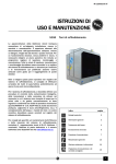
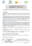
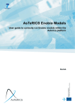
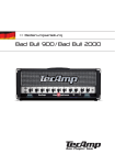
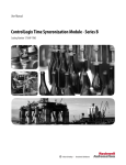
1756HP-HTB-S
I/O SLAVE
USER MANUAL
Rev 1.4 – September 2005
1756HP-HTB-S - User Manual Rev 1.4
Table of Contents
Chapter 1
Chapter 2
Chapter 3
Chapter 4
Chapter 5
Chapter 6
Appendix A
Appendix B
Appendix C
Appendix D
Introduction.......................................................................................................3
Module Accessories .........................................................................................4
Module Operation.............................................................................................4
Installing the Module ........................................................................................5
Configuring the Module ....................................................................................6
I/O Address Map ............................................................................................10
Overview of hisec IO network ........................................................................13
modulestatus ..................................................................................................14
Recommended Data Structures.....................................................................15
Specifications .................................................................................................16
.
Page 2 of 16
1756HP-HTB-S - User Manual Rev 1.4
CHAPTER 1
INTRODUCTION
Hiprom presents the 1756HP-HTB-S Hitachi interface module. The 1756HP-HTB-S and
the 1756HP-HTB-M 1 modules together provide an interface between existing Hitachi
control systems and new Allen Bradley ControlLogix PLC’s. The 1756HP-HTB-S (slave)
module is able to emulate an entire I/O network, satisfying the Hitachi CPU’s required
connection to I/O. Reference can be made to Appendix A which details the HISEC IO
network.
The module fits directly into any single slot within a ControlLogix System and is configured
in RSLogix5000 using the Generic Profile. A Brad Harrison Nano-Change (M8) Receptacle
provides a physical connection for the Hitachi signaling.
This document serves to describe the functionality, installation, configuration and use of
the module.
1
Reference can be made to the 1756HP-HTB-M User Manual for detailed information regarding this manual
.
Page 3 of 16
1756HP-HTB-S - User Manual Rev 1.4
CHAPTER 2
MODULE ACCESSORIES
Each 1756HP-HTB-S package includes the following components:
•
•
1756HP-HTB-S module
2m Patch lead
CHAPTER 3
MODULE OPERATION
The 1756HP-HTB-S module is designed to operate within the Allen-Bradley ControlLogix
PLC system. All power required for the module’s operation is derived from the 1756
backplane.
Alphanumeric Display
Status LEDs
Reserved RJ45 Port
Brad Harrison Nano-Change
(Hitachi Interface)
Figure 3.1 : 1756HP-HTB-S Layout
.
Page 4 of 16
1756HP-HTB-S - User Manual Rev 1.4
The current status of the module is conveyed to the user by means of the 3 bi-color Status
LED’s and the alphanumeric LED display. Appendix B details the various states of the
LEDs and messages of alphanumeric display.
The following information is available to the user directly across the backplane by means
of a scheduled connection:
•
•
Hitachi I/O data (for a slot configured as an input module)
Hitachi slot status information.
The Brad Harrison Nano-Change Receptacle located on the bottom of the module
provides an external connection for the Hitachi interface. The board is accompanied with
the respective 2m five core patch cable, of which the Hitachi cables are white and black.
CHAPTER 4
INSTALLING THE MODULE
The module is equipped with RIUP (Removal and Insertion Under Power) circuitry
enabling the module to be installed or removed from the chassis while power is applied.
.
Page 5 of 16
1756HP-HTB-S - User Manual Rev 1.4
CHAPTER 5
CONFIGURING THE MODULE
A direct connection between the controller and the 1756HP-HTB-S module is required to
transfer I/O data to and from the module.
5.1.
Establishing the Direct Connection
This section describes the procedures necessary to configure the 1756HP-HTB-S module
within the ControlLogix system. Each 1756HP-HTB-S module must be owned by a single
ControlLogix controller.
The 1756 Generic Module is used in RSLogix5000 to configure the module. The
configuration of the module is detailed in the table below.
CommFormat
Description
Input
Output
Configuration
Min
Data Format
Data – DINT
Connection parameters
Instance
1
2
4
RPI
5 msec
Max
Size
32 (32 Bit)
32 (32 Bit)
12 (8 Bit)
750.0 msec
Table 5.1 : 1756HP-HTB-S connection parameters.
The steps required to add a new 1756HP-HTB-S module are detailed below.
Figure 5.1 : Right-click on I/O Configuration and select New Module
.
Page 6 of 16
1756HP-HTB-S - User Manual Rev 1.4
Figure 5.2: Select Generic 1756 Module (1756-MODULE )
Figure 5.3: Configure module’s parameters
.
Page 7 of 16
1756HP-HTB-S - User Manual Rev 1.4
Figure 5.4: Configure module’s RPI (Requested Packet Interval)
Before a connection is established between the 1756HP-HTB-S module and a
ControlLogix processor, the Configuration data must be setup. The configuration data
specifies the
• Enabled Hitachi I/O slots and direction as either an output or input
• Low, medium and high diagnostic thresholds.
The format of the configuration data is illustrated below.
BIT
BYTE
0
1
2
3
S7E
S15E
S23E
S31E
4
5
6
7
IO7
IO15
IO23
IO31
8
9
10
11
7
6
5
4
3
2
1
I/0 Enable
S6E
S5E
S4E
S3E
S2E
S1E
S14E S13E S12E S11E S10E S9E
S22E S21E S20E S19E S18E S17E
S30E S29E S28E S27E S26E S25E
Input / Output
IO6
IO5
IO4
IO3
IO2
IO1
IO14 IO13 IO12 IO11 IO10
IO9
IO22 IO21 IO20 IO19 IO18 IO17
IO30 IO29 IO28 IO27 IO26 IO25
Diagnostic Threshold levels
Low Threshold
Medium Threshold
High Threshold
Reserved
0
S0E
S8E
S16E
S24E
IO0
IO8
IO16
IO24
The first 4 bytes (SnE where n = Extended Slot number) of the Configuration Image
indicate the Hitachi enabled slots.
“1” = Enabled,
“0” = Disabled
.
Page 8 of 16
1756HP-HTB-S - User Manual Rev 1.4
The next four bytes (IOn where n = Extended Slot number) of the Configuration Image
specify whether the enabled slots are either of type Input or Output:
“1” = Output
“0” = Input
Note: The 1756HP-HTB-M can only support 30 slots (i.e 0..29)
The remaining fields to be configured are those of the threshold levels. The module
continuously records the number of successful transactions for each enabled slot within a
specific time frame. The thresholds levels that are specified within the configuration file
create ranges as illustrated below that are then used for diagnostic display purposes (refer
to Appendix B).
Threshold Levels
X Counts
(Network
Dependent)
High
Medium
Low
0%
Once a module’s configuration data has been downloaded to the controller, it will establish
a connection with the module. Should the configuration of the 1756HP-HTB-S change, the
module will need to be reset. A connection will fail if there is inappropriate configuration
data, this includes:
•
•
•
The specified size of the Input, Output, or Configuration size is incorrect
The assembly instance of the input, Output and Configuration is incorrect
An RPI that does not fall within the specified range
The module utilizes a system watchdog to ensure the integrity of the connection to the
controller, refer to the Output Image.
.
Page 9 of 16
1756HP-HTB-S - User Manual Rev 1.4
CHAPTER 6
I/O ADDRESS MAP
The input and output image of the 1756HP-HTB-S module is defined in the following
sections.
6.1.
Input Image
Figure 6.1 : Connected Input Image
6.2.
Field/Value
Data
Enabled
Input Image Description
Description
Output Data
If module is configured as an output this field
reflects the current data of the associated output
Hitachi slot. If the associated Hitachi slot is
configured as an input, the data will display
0x0000
Slot Enable
0 = Hitachi Slot not enabled
1 = Hitachi Slot is enabled
Direction
Slot type: Indicates the direction / type of module
located in the associated slot
0 = Input module
1 = Output module
Status
Module status: Should the module in the
associated slot be enabled this bit indicates the
current status of that module
1 = Associated slot is operating correctly
0 = Associated slot has faulted. One can refer to the
Timeoutand Transcount for further details.
Location
Type
Local:s:I.Data[n].0..15
INT
Local:s:I.Data[n].16
BIT
Local:s:I.Data[n].17
BIT
Local:s:I.Data[n].18
BIT
.
Page 10 of 16
1756HP-HTB-S - User Manual Rev 1.4
Timeout bit: Indicates that a response was not
received from the associated slot within a specific
timeframe.
1 = No fault, data received
0 = No response was received from the associated
slot
Timeout
Transcount
Count of successful transactions with the
respective extended slot within a given time
frame.
Local:s:I.Data[n].19
Local:s:I.Data[n].24..31
BIT
SINT
Warning:
It is important to ensure that the diagnostic status information is used in the
PLC logic in order to detect possible module or network failure. Failing to do
so could result in possible equipment damage or personal injury
6.3.
Output Image
Words 0..29
Should a slot be configured as an input, the respective output word will read the input data.
The card uses this data to emulate the input network, satisfying the Hitachi CPU’s
connection to the network. Thus, assuming slot 6 of the Hitachi network has been
configured as a Hitachi input card, the data corresponding to the slot can be written to
Local:s:O.Data[6].
Field
Output Data
Description
Input data to be written to a Hitachi CPU.
Location
Type
Local:s:O.Data[n]0..15
INT
.
Page 11 of 16
1756HP-HTB-S - User Manual Rev 1.4
Word 30
WatchDog
Word 30 (Local:s:O.Data[30]) of the output image is reserved for a watchdog. The
watchdog ensures that the connection with the controller has been established and
continues to remain connected, thus ensuring that no inaccurate data can be written/read
to/from the Hitachi network.
The watchdog is an integer (word) that must be changed within every 10ms. Should the
value not change the module will fault and this will be indicated via the alphanumeric
display and LED statuses. Transactions with the Hitachi Network will terminate when the
watchdog has faulted, and resume once the watchdog begins updating again.
.
Page 12 of 16
1756HP-HTB-S - User Manual Rev 1.4
APPENDIX A
OVERVIEW OF HISEC IO NETWORK
Network Topology
The Hitachi HISEC I/O network is a single master, multiple slave network connected by
means of a multi-dropped single pair of wires.
The master, typically an H02 CPU or a CE module connected to an H04 CPU, is
responsible for interrogating (inputs) and commanding (outputs) on each logical slot on the
network. Each slot is processed in logical slot ascending order although the protocol does
not require this. That is, slot 0 is processed, then slot 1, and so on. After slot 31 has been
processed it rolls over to slot 0 and the sequence is repeated.
The logical slot number (0-31), also referred to as the extended slot number, is the unique
slot address on the network. For the first rack on the network, (station address zero), it is
simply the physical slot number, numbering from 0 ( on the left) to n-1 (on the right), where
n is the number of logical slots in the physical rack. For subsequent racks, where the rack
station address is greater than zero the extended slot number can be calculated as follows
:
Extended Slot = ( ST * 2 ) + y
Where :
ST = station address as configured by the ST dial on the rack controller (PST360) module,
y = physical slot number ( 0 through n – 1, where n is the logical rack size )
The network does not differentiate on how the logical address is determined. For example,
the modules in one 8 slot rack (with ST = 0), are addressed in the exact same manner in
which two 4 slot racks ( with ST = 0 and ST = 2 respectively) are addressed.
.
Page 13 of 16
1756HP-HTB-S - User Manual Rev 1.4
MODULESTATUS
APPENDIX B
The following sections describe the status indicators of the module :
Status LEDs
LED
DESCRIPTION
OK
Module Status
Enabled Slots
ACT
COM
6.4.
Init
Frn
WDog
nn33
Nn 3
nn X
nnXX
All Slots OK
STATUS
Solid Red
Flashing Red
Flashing Green
Green
Solid Red
Green
Solid Green
Solid Red
MEANING
Initialization or Watch Dog Fault
Major Fault
Minor Fault
Module operating correctly
Watchdog Error or No slots enabled
Slots Enabled with no watchdog error
All enabled slots communication
operating correctly
A timeout has occurred for the update
time for one or more of the enabled
slots
Status Display
Initialization of Module
The module is initialized only on power-up.
Firmware Revision
The firmware revision number is displayed on power-up.
WatchDog
Watchdog fault
Successful Transactions between High threshold and 100% (nn =
Extended slot)
Successful Transactions between Meduim and High threshold (nn =
Extended slot)
Successful Transactions between Low and Medium threshold (nn =
Extended slot)
Successful Transactions between 0% and Low threshold (nn =
Extended slot)
.
Page 14 of 16
1756HP-HTB-S - User Manual Rev 1.4
APPENDIX C
RECOMMENDED DATA STRUCTURES
This Appendix provides a detailed description of recommended data structures that can be
used.
Name
EnableSlot
TypeSlot
ThresholdLow
ThresholdMed
ThresholdHigh
Datatype
BOOL[32]
BOOL[32]
SINT
SINT
SINT
Style
Decimal
Decimal
Decimal
Decimal
Decimal
Table D.1: Slave Module Configuration Data Structure
Name
InputData
Enabled
Direction
Status
TimeOut
Reserved0
Reserved1
Reserved2
Reserved3
TransCount
Datatype
INT
BOOL
BOOL
BOOL
BOOL
BOOL
BOOL
BOOL
BOOL
SINT
Style
Decimal
Decimal
Decimal
Decimal
Decimal
Decimal
Decimal
Decimal
Decimal
Decimal
Table D.2: Slave Module Input Image Word Structure
Name
Data
Reserved
DataType
INT
INT
Style
Decimal
Decimal
Table D.3: Slave Module Output Image Word Structure
.
Page 15 of 16
1756HP-HTB-S - User Manual Rev 1.4
APPENDIX D
SPECIFICATIONS
Parameter
Specification
General
Module Location
Backplane Current
RPI
Any Slot
Electrical
515mA @ 5.1V
3mA @ 24V
Schedules Connection Parameters
5ms to 750ms
.
Page 16 of 16