1
QUICK START GUIDE | KURZANLEITUNG | GUIDE DE DÉMARRAGE RAPIDE
ENGLISH
16
01
05
18
17
02
06
03
07
20
19
21
08
10
09
GERMAN
04
22
24
23
11
25
26
13
FRANÇAIS
12
01.
02.
03.
04.
05.
06.
07.
08.
09.
10.
11.
12.
13.
14.
15.
16.
17.
18.
19.
20.
21.
22.
23.
24.
25.
26.
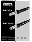
Priming button
Priming chamber
Mechanical cartridge
Mechanical cartridge cup
Chemical cartridge cap
Chemical cartridge
Chemical cartridge cup
AquaStop release lever
AquaStop valve lever
AquaStop
Filter head
Biological basket cover
Biological baskets [G3 x 2/G6 x 3]
Filter canister gasket
Filter canister
Cross rim assembly
Rim attachment
Output nozzle + extension
Hosing
Spray bar suction cups
Spray bars
Telescopic intake stem
Intake strainer
Cartridge lid
Impeller assembly
Impeller cover + “O” ring
01.
02.
03.
04.
05.
06.
07.
08.
09.
10.
11.
12.
13.
14.
15.
16.
17.
18.
19.
20.
21.
22.
23.
24.
25.
26.
Ansaugknopf
Ansaugkammer
Mechanischer Filtereinsatz
Mechanischer Filterbehälter
Chemische Einsatzabdeckung
Chemischer Filtereinsatz
Chemischer Filterbehälter
AquaStop Auslösehebel
AquaStop Ventilhebel
AquaStop
Filterkopf
Korbabdeckung für biologische Medien
Körbe für biologische Medien [G3 x 2/G6 x 3]
Filterbehälterdichtung
Filterbehälter
Rahmenbefestigungsteile
Rahmenbefestigung
Wasseraustrittsstutzen + Verlängerung
Schlauch
Düsenstrahlrohr-Saughalter
Düsenstrahlrohre
Teleskop-Ansaugrohr
Ansaugkorb
Filterdeckel
Antriebsmagneteinheit
Antriebsmagnetabdeckung + O-Ring
01.
02.
03.
04.
05.
06.
07.
08.
09.
10.
11.
12.
13.
Bouton d’amorçage
Chambre d’amorçage
Cartouche de filtration mécanique
Boîtier de la cartouche de filtration mécanique
Couvercle de la cartouche de filtration chimique
Cartouche de filtration chimique
Boîtier de la cartouche de filtration chimique
Manette de dégagement de la soupape AquaStop
Manette de la soupape AquaStop
AquaStop
Tête du filtre
Couvre-paniers de la masse filtrante biologique
Paniers de la masse filtrante biologique
(G3 x 2/G6 x 3)
Joint d’étanchéité du filtre
Cuve du filtre
Bloc de raccordement
Fixation au cadre
Bec de sortie d’eau + rallonge
Tuyaux
Ventouses du tube diffuseur
Tubes diffuseurs
Tube d’admission téléscopique
Crépine d’admission
Couvercle des cartouches du filtre
Bloc de la couronne
Couvercle de la couronne + joint d’étanchéité
14
15
EN.2
H Y D R O T E C H P E R F O R M A N C E M O N I T O R | A D VA N C E D F I LT R AT I O N S Y S T E M
14.
15.
16.
17.
18.
19.
20.
21.
22.
23.
24.
25.
26.
ENGLISH
IMPORTANT SAFETY INSTRUCTIONS
WARNING - To guard against injury, basic safety precautions should be observed.
READ AND FOLLOW ALL SAFETY INSTRUCTIONS
To guard against injury, basic safety precautions should be
observed when handling the Fluval Canister Filter, including
the following:
1.
READ AND FOLLOW ALL
SAFETY INSTRUCTIONS and all
the important notices on the appliance before using.
Failure to do so may result in damage to the unit.
2. DANGER – To avoid possible electric shock, special
care should be taken since water is employed in the
use of aquarium equipment. For each of the following
situations, do not attempt repairs yourself; return the
appliance to an authorized service facility for service or
discard the appliance.
A. If the appliance falls into the water, DON’T reach for it!
First unplug it and retrieve it. If electrical components
of the appliance get wet, unplug the appliance
immediately.
B. If the appliance shows any sign of abnormal water
leakage or if RCD (or GFCI- Ground Fault Current
Interrupter) switches off disconnect the power supply
cord from mains and remove pump from water.
C. Carefully examine the appliance after installation.
It should not be plugged if there is water on parts not
intended to be wet.
D. Do not operate any appliance if it has a damaged cord
or plug, or if it is malfunctioning or it is dropped or
damaged in any manner. The power cord of this
appliance cannot be replaced; if the cord is damaged,
the appliance should be discarded. Never cut the cord.
The display label of this appliance cannot be replaced; if
the display label is damaged or not fully adherent, the
appliance should be discarded.
E. To avoid the possibility of the appliance plug or
receptacle getting wet, position the appliance to one side
of a wall mounted receptacle to prevent water from
dripping onto the receptacle or plug.
A “drip loop” (see photo) should be arranged by the user for
the cord connecting appliance to a
receptacle. The “drip loop” is that
part of the cord below the level of the
receptacle or the connector if an
extension cord is used, to prevent
water traveling along the cord and
coming in contact with the receptacle.
If the plug or receptacle does get wet, DON’T unplug the
cord. Disconnect the fuse or circuit breaker that supplies
power to the appliance. Then unplug and examine for
presence of water in receptacle.
3. WARNING - Close supervision is necessary when any
appliance is used by or near children. This appliance
is not intended for use by persons (including children)
with reduced physical, sensory or mental capabilities,
or lack of experience and knowledge, unless they have
been given supervision or instruction concerning use
of the appliance by a person responsible for their safety.
Children should be supervised to ensure that they do not
play with the appliance.
4. To avoid injury, do not touch moving parts or hot
parts.
5. CAUTION – Always unplug or disconnect all appliances
in the aquarium from electricity supply before
placing hands in water, before putting on or taking off
parts and while the equipment is being installed,
maintained or handled. Grasp the plug and pull to
disconnect. Never yank cord to pull plug from outlet.
Always unplug an appliance from an outlet when not
in use.
6. This is an aquarium filter-pump. Do not use this filter
pump for other than intended use (i.e.: do not use in
swimming pools, bathrooms, etc.). The use of
attachments not recommended or sold by the appliance
manufacturer may cause an unsafe condition. This
filter-pump is not submersible. Never put the filter head
in water or under water jets.
Ê UÊÊÌÊÕÃiÊÌ
ÃÊwÌiÀ«Õ«ÊÊÃÜ}Ê«ÃÊÀÊÌ
iÀÊ
situations where people are immersed.
Ê UÊ/
ÃÊwÌiÀ«Õ«ÊÃÊÃÕÌ>LiÊvÀÊÕÃiÊÊÜ>ÌiÀÊÌi«iÀ>ÌÕÀiÃÊ
up to 35 °C.
Ê UÊÊÌÊÕÃiÊÌ
ÃÊwÌiÀ«Õ«ÊÜÌ
Êy>>LiÊÀÊ`À>LiÊ
liquids.
7. This filter pump is suitable for INDOOR use only. Do not
install or store the appliance where it will be exposed to
the weather or to temperatures below freezing.
8. Make sure that the filter-pump is securely installed
before operating it. Do not allow pump to run dry.
9. If an extension cord is necessary, a cord with proper
rating should be used. A cord rated for less amperes or
watts than the appliance rating may overheat. Care
should be taken to arrange the cord so that it will not be
tripped over or pulled. The connection should be carried
out by a qualified electrical installer.
10.
SAVE THESE INSTRUCTIONS
For the complete use and understanding of this product
it is recommended that you read this manual thoroughly
and understand all the steps involved. Failure to do so
may result in damage to this product.
Q U I C K S TA R T G U I D E
EN.3
INSTALLATION AND SETUP
IMPORTANT: Read all instructions before beginning.
Ê UÊÀ LiÃÌ ÀiÃÕÌÃ] Ì« vv Ü>ÌiÀ >µÕ>ÀÕ
before beginning setup.
Ê UÊÜ {xÈä ÕÌià vÀ ÃiÌÕ« >` ÃÌ>>Ì°
Ê UÊv >Ì >Þ Ìi ÞÕ ii` Ài `iÌ> ÜÌ
Ì
i
instruction, please visit www.fluval-g.com to
follow a photo slide show of these step-by-step
instructions.
Ê UÊ/Ã ÀiµÕÀi`\ 1ÌÌÞ vi À > «>À v ÃVÃÃÀÃ
Ê UÊ,iÛi Ì
i «Ài wÌiÀ V>ÀÌÀ`}i] V>Ìi` Ì
i
left (when facing the filter), by turning the knob
counter-clockwise from the “ ” position to the
“
” position. Pull out the cartridge.
Ê UÊ,Ì>Ìi Ì
i «ÀiwÌiÀ V>ÀÌÀ`}i >ÌVVÜÃi Ì
separate it from the priming chamber.
STEP 1: 1«>V >` `iÌvÞ > «>ÀÌð -ii *>ÀÌÃ
Page for a visual guide.
STEP 3: INSTALLING THE FILTER
A. Preparation of Pre-Filter Cartridge
G.4
1Ã} Ì
i
>`iÃ] vÌ
out the biological basbaskets (the Fluval G3 has
two baskets; the Fluval
G6 has three biological
baskets).
G.7
G.2
Ê UÊ,Ãi Ì
i Ã`i >` ÕÌÃ`i v Ì
i V>ÀÌÀ`}i
with fresh water to remove any impurities. Note
that debris is collected on the interior of the
cartridge.
Ê UÊ,i«>Vi Ì
i V>ÀÌÀ`}i VÕ« >` >ÌÌ>V
Ì
i
mechanical cartridge to the priming chamber
using a clockwise motion.
Ê UÊ*ÕÌ Ì
i iV
>V> V>ÀÌÀ`}i >ÃÃiLÞ >Ã`i
(preferably into a bucket.)
Maintenance Note: The mechanical cartridges
should be rinsed every 14 days— sooner if the
“Alert low flow” warning appears. The filter cartridge
included is a general usage cartridge. To remove
smaller debris in salt water or in low-sediment
aquariums, a fine cartridge can be purchased.
To find an online retailer visit www.fluval-g.com.
Ê UÊ,i>` Ài >LÕÌ wÌiÀ i`> V
Vià >Ì
www.fluval-g.com.
Ê UÊivÀi Ài«>V} Ì
i V>ÀÌÀ`}i V>«] V
iV vÀ >Þ
particles or debris on the outer lip or underneath
the cap. Debris in either area can prevent a
proper seal from taking place.
Ê UÊ,i«>Vi V>ÀÌÀ`}i V>« >` ÀiÃiÀÌ V>ÀÌÀ`}i Ì
cartridge cup. It can only be re-assembled
following the correct left to right orientation.
See arrows in G.3. Re-attach cartridge cup to
chemical cartridge cap.
Ê UÊ*ÕÌ Ì
i V
iV> V>ÀÌÀ`}i >ÃÃiLÞ >Ã`i°
C. Insert the filter gasket
2
B. Preparation of Chemical Filter Cartridge
Ê UÊ,iÛi Ì
i V
iV> wÌiÀ V>ÀÌÀ`}i] V>Ìi`
the right (when facing the filter), by turning the
knob counter-clockwise from the “ ” position
the “
” position. Pull out the cartridge.
G.5
Release the chemical
cartridge cup from the
assembly head by
pushing against one of
the two marked black
clips located in the
middle of the cartridge.
While pressing the clips,
pull the cup downwards.
Open the cartridge lid.
/
i ÃÛiÀ +1-/"*
valve lever must be
completely up and the
black Aquastop release
lever must be
completely pushed
down in order to open
the lid.
G.1
G.3
G.6
H Y D R O T E C H P E R F O R M A N C E M O N I T O R | A D VA N C E D F I LT R AT I O N S Y S T E M
Ê UÊ/>i Ì
i L>ÃiÌà >` L}V> `iÃ Ì > ð
Remove G-nodes from the plastic bags, mixing the
small and large G-nodes evenly into each basket.
G.8
3
EN.4
D. Biological Media Baskets
Ê UÊvÌ ÕÌ Ì
i L}V> i`> L>ÃiÌ VÛiÀ >` «ÕÌ
it aside.
If using another loose or
granulated chemical
media i.e. Fluval Lab
Series Nitrate or PhosPhosphate remover, fill the
cup to 1 cm below the
top rim.
To remove the cartridge
from its red dirt colleccollection cup, simultaneously
squeeze the ridged areas
found on either side of
the cup’s grooves.
CAUTION: DO NOT PLUG IN FILTER UNTIL SETUP
IS COMPLETE AND UNIT IS FILLED WITH WATER.
STEP 2: FILTER PLACEMENT
This is a gravity-fed system! For it to work properly,
all installation requirements must be properly
followed:
Ê UÊ/
i Ì« v Ì
i wÌiÀ ÕÃÌ Li >Ì i>ÃÌ Óä °
(50 cm) below your aquarium’s water level but
never more than 4.9 ft. (150 cm). The hosing
supplied with the unit is 9.8 ft. (3 m) long. Do not
use longer and/or different type hosing as the
«À} ivwViVÞ >` Ü>ÌiÀ yÜ À>Ìi VÕ` Li
diminished and the filter may not operate correctly.
Ê UÊNEVER INSTALL THE FILTER ABOVE THE
WATER LEVEL. The aquarium water level should
never be more than 6 in. (15 cm) below your
aquarium rim.
Ê UÊÀ LiÃÌ «iÀvÀ>Vi] Ì
i wÌiÀ Ã
Õ` Li «>Vi`
completely beneath the aquarium in such a way
Ê Ê Ì
>Ì Ì
i +1-/"* >ÃÃiLÞ Ã >Ü>ÞÃ ÜÌ
easy reach and can be removed easily for
maintenance purposes.
Ê UÊv ÕÃ} Ì
i V>ÀL V>ÀÌÀ`}i «ÀÛ`i` ÀiÛi Ì
from the cartridge cup and then remove the
plastic bag. After rinsing it thoroughly with tap
water, place the cartridge back into the bottom
cup making sure it’s properly aligned.
Open the silver
metal lid fasteners
located on each
corner of the filter.
Take off the filter
head and carefully
set it aside so not
to damage the
sensors on the
underside of
the lid.
Align the red silicone
seal into the black
groove located around
the interior rim of the
canister. Run your
finger all the way
around the gasket to
make sure it is seated
properly.
Leave enough space at
the top—no nodes should
be protruding from the
upper edges of the
baskets. To avoid
problems when stacking
the baskets, there should
be a minimum 5mm
between the basket edge
and G-nodes.
Ê UÊ`` Ài `iÃ] v `iÃÀi`°
Ê UÊ,Ãi i>V
L>ÃiÌ Ì
ÀÕ}
Þ Õ`iÀ ÀÕ} Ì>«
water to remove any dust particles.
Ê UÊ*>Vi L>ÃiÌÃ L>V Ì Ì
i V>ÃÌiÀ] V>ÀivÕÞ
aligning large grooves on the baskets with the
edges inside the canister.
Ê UÊ*>Vi Ì
i L}V> L>ÃiÌ VÛiÀ L>V Ì« v
the biological media baskets.
Ê UÊ} Ì
i wÌiÀ
i>` Ì
i V>ÃÌiÀ° *ÕÃ
`Ü
so that all four corners of the lid are all the way
down. If any of the corners won’t go all the way
down, check that all corner fasteners are fully
opened.
Do not force.
Ê UÊ7
i Ì
i wÌiÀ
i>` Ã «À«iÀÞ >}i`] VÃi >
four metal lid fasteners.
Q U I C K S TA R T G U I D E
EN.5
C. Install Output nozzles
Ê UÊ/
iʺ9»ÊÕÌiÌÊViÃÊÜÌ
ÊÌ
iÊÕÌ«ÕÌÊââiÃÊ
attached. To use the spray bars, first remove the
output nozzles by twisting them to one side so
they pop off the “Y”. You can then attach the
spray bars directly to the “Y” outlet.
G.10
G.9
Replace the mechanical and chemical cartridges
back into place making sure to align them properly
and then turning the knobs clockwise to “ ”
cartridges into place.
If the cartridge lid doesn’t close, the cartridges have
not been installed properly.
STEP 5: CONNECTING HOSES
Important: Hosing should always follow a straight
path from the filter to the aquarium rim with some
slack but no loops. The filter will not work efficiently if
the hose is too long or too short.
A. Install the Aquastop
Ê UÊvÌÊÌ
iÊÃÛiÀÊ+1-/"*ÊÛ>ÛiÊiÛiÀÊÊÌ«ÊvÊ
the filter to a full upright position. Next lift the
Aquastop release lever to the left. Important: to
avoid damaging the Aquastop levers, always
follow the recommended sequences/procedures
and never force anything.
B. Connect the intake hose
G.14
The intake hose will connect to left side of the
+1-/"*ÊÛ>ÛiÊ`ÜÊ>ÀÀÜ®°Ê*ÕÃ
ÊiÊi`ÊvÊÌ
iÊ
hose all the way onto the barbed adaptor, turn the
nut counter-clockwise as tightly as possible without
forcing it.
STEP 4: INSTALL RIM ATTACHMENTS
A. Placement
G.15
Insert two suction cups
on each side of the rim
attachment assemblies
so the suction cups are
facing each other.
G.11
Ê UÊ"iÊÀÊ>ÌÌ>V
iÌÊÜÊ
`ÊÌ
iÊÌ>iÊÃÌÀ>iÀÊ
and the other the output nozzle or spray bars.
At opposite ends, place
the rim assembly over
aquarium’s back rim,
making sure the rim with
the nut is on the outside.
G.13
ÃiÀÌÊÌ
iÊ+1-/"*Ê6>ÛiÊÌÊÌ
iÊÌ«ÊvÊÌ
iÊ
filter, with indicator arrows facing front and close
Ì
iÊ+1-/"*ÊÀii>ÃiÊiÛiÀ°Ê/
ÃÊi}>}iÃÊÌ
iÊ
+1-/"*ÊÛ>Ûi°Ê/
iÊ«ÕÊÌ
iÊ>µÕ>ÃÌ«ÊÛ>ÛiÊ
lever down.
H Y D R O T E C H P E R F O R M A N C E M O N I T O R | A D VA N C E D F I LT R AT I O N S Y S T E M
G.17
After having topped up
the aquarium with water,
quickly and vigorously
push the priming
button all the way down
2-3 times until the water
ÃÌ>ÀÌÃÊyÜ}ÊÌÊÌ
iÊ
filter.
Ê UÊ7
iÊÌ
iÊwÌiÀÊ
>ÃÊV«iÌiÞÊwi`ÊÜÌ
ÊÜ>ÌiÀÊ
and all air bubbles have stopped coming out of
return nozzles connect it to the power supply
outlet.
Ê UÊ/
iÊ
Ê`ë>ÞÊÜÊÃÜÌV
ÊÊ>`Ê>vÌiÀÊ>ÊÃ
ÀÌÊ
pause it will show the start up and setup
sequence of the filter. Once the start sequence
Ê Ê
>ÃÊi`i`]ÊÌ
iÊ«Õ«ÊÜÊÌ>ÌiÊÌ
iÊÜ>ÌiÀÊyÜ]Ê
provided the filter is completely filled with water.
The pump will not operate if the filter is not
completely full of water.
Ê UÊ"ViÊÌ
iÊÜ>ÌiÀÊÃÊyÜ}Ê«À«iÀÞ]ÊV
iVÊÌ
iÊ
aquarium water level again and, if necessary,
restore it to adequate levels.
STEP 7. FILTER SETTINGS
You are now ready to set up your filter options using
the menus.
C. Connect the output hose
Ê UÊ/
iÊÕÌ«ÕÌÊ
ÃiÊÜÊViVÌÊÊÌ
iÊÀ}
ÌÊÃ`iÊvÊ
the Aquastop (up arrow).
Repeat this same
procedure used for the
intake hose to connect
the hose for the output
hose.
G.12
EN.6
UÊ-ÌÀiÌV
ÊÌ
iÊ
ÃiÊÕ«ÊÌÊ
the intake cross rim
>ÃÃiLÞÊ°Ê1Ã}Ê
scissors or a utility knife,
cut the hose just above
the lock nut.
Ê UÊ/>iÊÌ
iÊVÀÃÃÊÀÊ>ÃÃiLÞÊvvÊÌ
iÊÀÊ
attachment and push the hose onto the barbed
connector, turn the nut lock clockwise securing
the hose to the rim connector. Place the intake
assembly back onto the rim attachment, pressing
it into place until you hear it ”click.”
NOTE: Don’t force the silver valve lever or release
lever. If it doesn’t close easily then you need to
reinstall the Aquastop assembly making sure to align
it properly.
B. Install Telescopic intake stem
Ê UÊ*ÕÃ
ÊÌ
iÊÌiiÃV«VÊÌ>iÊÃÌiÊvÕÞÊÌÊÌ
iÊ
cross rim assembly up to the top. The intake
strainer must be placed at least 3 in (7.5cm)
from the bottom of the aquarium gravel.
Important: Position the telescopic intake strainer
as far away as possible from any air source (e.g. air
stones, aeration devices, protein skimmers, the output nozzles or spray bars). Air entering the intake
strainer will reduce filter efficiency.
STEP 6. STARTING THE PUMP
G.16
Important: Hosing should always follow a straight
path from the filter to the aquarium rim, with some
slack, but no loops. The shorter the hosing, the
better the unit will perform. Do not cut too short.
If necessary, you can always cut it shorter later.
Q U I C K S TA R T G U I D E
EN.7
MENU SETTINGS
7.
6.
Start up Screen
5.
8.
ESC
4.
9.
1.
2.
3.
When the filter is first turned on the welcome screens
will be displayed with the messages “Fluval G3 / G6”
“Language Selection” then “initializing.” When the
language screen is displayed (English is the default
setting) other language choices can be made ( French
(FR), German (D), Spanish (ES), Italian (IT). To chose an
alternate language use the scroll keys to move to the
selected language. Press Enter to register the
language. If no language is chosen, the filter will move
to the default English setting. See the section on
Global Settings for more information.
MAIN MENU
1.MECH: Shows the elapsed days
from last recorded maintenance
operation of the mechanical
filtration cartridge.
2.CHEM: Shows the elapsed days
from last recorded chemical
cartridge maintenance operation.
3.BIOL: Shows the elapsed weeks
from last recorded biological
maintenance operation.
4.SCROLL UP/DOWN:
Both keys allow you to scroll to
and through menu choices as well
as and increasing and decreasing
values.
5.WATER FLOW: Displays the
>««ÀÝ>ÌiÊyÜÊÀ>Ìi°Ê7
iÊ>Ê
£ää¯ÊyÜÊÃÊ`iÌiVÌi`ÊÌ
iÊÌÀ>}iÊ
will be full and water will move
Ì
ÀÕ}
ÊÌ
iÊÌÕLiðÊ7
iÊÌ
iÊyÜÊ
rate decreases, the triangle will
empty accordingly.
6.T°C: Displays the aquarium
water temperature measured.
If electrical supply is 50Hz the
temperature is automatically set
to Celsius degrees (°C), if the
electrical supply is 60Hz, the
temperature is set to Fahrenheit
degrees (°F).
7.EC _S/cm: Displays the value
of water electrical conductivity
monitored by the filter by automatically distinguishing if it’s a marine
or fresh water aquarium. Allow
48 hrs for proper calibration.
8.ESCAPE KEY: Repeatedly
pressing the “ESC” key brings you
back to the main screen.
9.ENTER KEY: This key confirms
and then sets the information
entered. If you press the “ESC” key
without having first pressed the
“ENTER” key to confirm your data
will not be saved.
GLOBAL and OPERATIONAL SETTINGS MENUS
1. To reach either menu from the Main Menu, use the scroll keys.
2. When the desired Menu is displayed, press “Enter” to scroll through the available
options within same Menu.
3. When the desired option is highlighted, press “Enter” to open its specific sub-screen.
“GLOBAL SETTINGS” MENU
This menu allows you to set the options of:
Display language, Screen contrast, Temperature
scale, Dimmer delay and Default setting.
To access the global settings menu press the scroll
key up or down.
EN.8
To set any options from this menu including options
on the submenus, use the following procedure:
Ê UÊ*ÀiÃÃʺÌiÀ»ÊÌÊ>VViÃÃÊÌ
iÊiÕ°Ê
Ê UÊ1ÃiÊÌ
iÊÃVÀÊiÞÃÊÌÊ
}
}
ÌÊÌ
iÊ`iÃÀi`Ê
selection.
Ê UÊ*ÀiÃÃʺÌiÀ»ÊÌÊiÌiÀÊÌ
iÊÃÕLÃVÀiiÊ
Ê UÊ" 9Êʺ-iÌÊ
ÌÀ>ÃÌ»Ê*ÀiÃÃʺÌiÀ»Ê>}>ÊÌÊ
activate the scroll keys (The value option will start
Ê Ê ÌÊy>Ã
®
Ê UÊ1ÃiÊÌ
iÊÃVÀÊiÞÃÊÌÊV
>}iÊÛ>ÕiðÊ
Ê UÊ*ÀiÃÃʺÌiÀ»ÊÌÊÀi}ÃÌiÀÊÌ
iÊÃiiVÌ°
Ê UÊvÊÊLÕÌÌÊÃÊ«ÀiÃÃi`]ÊÌ
iÊÃVÀiiÊÀiÌÕÀÃÊÌÊÌ
iÊ
previous settings after 3 minutes.
Ê UÊ
ÌÕÕÃÊ«ÀiÃÃ}ÊvÊÌ
iʺ-
»ÊiÞÊÜÊLÀ}ÊÞÕÊ
back to the main screen
H Y D R O T E C H P E R F O R M A N C E M O N I T O R | A D VA N C E D F I LT R AT I O N S Y S T E M
“OPERATIONAL SETTINGS” MENU
Within this menu you can set “Temperature and
Conductivity Alarm Points” as well as “Mechanical,
Chemical and Biological maintenance schedules”.
To access the “Operational Settings” menu press the
scroll keys up or down.
TEMPERATURE POINTS
The following options are available:
Water Temp: Displays the aquarium water
temperature.
Alert: Turns “ON / OFF” the “Alert Temperature,
out of range” message. When water temperature
goes out of the set temperature range, the T°C line
ÊÌ
iÊ>ÊÃVÀiiÊÜÊy>Ã
°Ê
Min/Max: Sets the min/max values for the water
temperature range. The minimum temperature can’t
be higher than the maximum and vice versa.
CONDUCTIVITY POINTS
The following options are available:
Conduct: Displays the water conductivity value.
Find more information on conductivity on
www fluval-g.com.
Salinity\Êë>ÞÃÊÜ>ÌiÀÊÃ>ÌÞÊÊ*-1°ÊSalinity only
appears if water is marine
Alert: Turns “ON / OFF “Alert Conductivity, out of
range” message. When conductivity goes out of
À>}iÊÌ
iÊ
ÊiÊÊÌ
iÊ>ÊÃVÀiiÊÜÊy>Ã
°Ê
Min/Max: Sets the min/max values for the water
conductivity range. The minimum conductivity can’t
be higher than the maximum and vice versa.
MECHANICAL SCHEDULE
The following options are available:
Elapsed Days: Counts the days elapsed since the
last recorded maintenance. This information is
displayed on the “MECH” line on the main menu. To
reset to zero use the scroll keys to select the value,
press enter to choose the option, use the scroll key
to choose “YES” and press “Enter”.
To set any options from this menu including options
on the submenus, use the following procedure:
Ê UÊ*ÀiÃÃʺÌiÀ»ÊÌÊ>VViÃÃÊÌ
iÊiÕ°Ê
Ê UÊ1ÃiÊÌ
iÊÃVÀÊiÞÃÊÌÊ
}
}
ÌÊÌ
iÊ`iÃÀi`Ê
selection.
Ê UÊ*ÀiÃÃʺÌiÀ»ÊÌÊiÌiÀÊÌ
iÊÃÕLÃVÀii°Ê
Ê UÊ1ÃiÊÌ
iÊÃVÀÊiÞÃÊÌÊ
}
}
ÌÊÌ
iÊ>`ÕÃÌ>LiÊ
value.
Ê UÊ*ÀiÃÃʺÌiÀ»Ê/
iÊÛ>ÕiÊÜÊÃÌ>ÀÌÊÌÊy>Ã
®Ê
Ê UÊ`ÕÃÌÊÌ
iÊÛ>ÕiÊÜÌ
ÊÌ
iÊÃVÀÊiÞÃ
Ê UÊ*ÀiÃÃʺÌiÀ»ÊÌÊÀi}ÃÌiÀÊÌ
iÊÃiiVÌ°
Ê UÊvÊÊLÕÌÌÊÃÊ«ÀiÃÃi`]ÊÌ
iÊ>vÌiÀÊÎÊÕÌiÃÊÌ
iÊ
screen returns to the main screen.
Ê UÊ
ÌÕÕÃÊ«ÀiÃÃ}ÊvÊÌ
iʺ-
»ÊiÞÊÜÊLÀ}ÊÞÕÊ
back to the main screen
Alert: Turns the warning message for “Mech”
maintenance alert “ON or OFF”.
Days to alert\Ê1ÃiÊÌ
iÊÃVÀÊiÞÃÊÌÊV
ÃiÊÌ
iÊ
days between the previous and next maintenance.
The highest number available is 99.
CHEMICAL SCHEDULE
The following options are available:
Elapsed Days: Counts the days elapsed since the
last recorded chemical maintenance. This
information is displayed on the “CHEM” line on the
main menu. To reset to zero use scroll keys to select
the value, press enter to choose the option, use the
scroll key to choose “YES” and press “Enter”.
Alert: Turns the warning message for “Chem”
maintenance alert “ON or OFF”.
Days to alert\Ê1ÃiÊÌ
iÊÃVÀÊiÞÃÊÌÊV
ÃiÊÌ
iÊ
days between the previous and next maintenance.
The highest number is 99.
BIOLOGICAL SCHEDULE
The following options are available:
Elapsed Weeks: Counts the weeks elapsed since
the last recorded biological maintenance. This
information is displayed on the “Biol” line on the
main menu. To reset to zero use scroll keys to
select the value, press “Enter” to choose “YES” and
press “Enter”.
Alert: Turns the warning message for “Bio”
maintenance alert “ON or OFF”
Weeks to alert\Ê1ÃiÊÌ
iÊÃVÀÊiÞÃÊÌÊV
ÃiÊÌ
iÊ
weeks between the previous and next maintenance.
The highest number is 99.
Q U I C K S TA R T G U I D E
EN.9
GERMAN
GRAPHIC DISPLAYS
These display screens have no adjustable settings but supply crucial system information.
WICHTIGE SICHERHEITSHINWEISE
/1 ÊqÊ<ÕÊ-V
ÕÌâÊÛÀÊ6iÀiÌâÕ}iÊÃ`Ê}ÀÕ`i}i`iÊ-V
iÀ
iÌÃÛÀi
ÀÕ}iÊâÕÊLi>V
Ìi°
BITTE ALLE SICHERHEITSHINWEISE LESEN UND BEFOLGEN
<ÕÊ-V
ÕÌâÊÛÀÊ6iÀiÌâÕ}iÊÃ`ÊLiÊ1}>}ÊÌÊ`iÊÕÛ>Ê
Außenfilter grundlegende Sicherheitsvorkehrungen zu beachten,
einschließlich der folgenden Hinweise:
1.
FILTER FLOW GRAPH
ë>ÞÃÊÌ
iÊ>««ÀÝ>ÌiÊyÜÊÀ>ÌiÊ`ÕÀ}ÊÌ
iÊ
last 48 days.
TEMPERATURE GRAPH
Displays the temperature trend during the last
8 days.
CONDUCTIVITY GRAPH
Displays the conductivity trend over the last
48 days.
ALARMS & WARNING MESSAGES
The “G” series software continuously monitors filter operations and will provide “Alert” signals for some
abnormal conditions. It also displays reminders about scheduled maintenance. When warnings or alerts are
displayed they will alternate with the Main Screen. If there is more than one warning message to display, the
system will display one message in order of priority.
LESEN UND BEFOLGEN SIE
ALLE SICHERHEITSHINWEISE
sowie alle wichtigen Hinweise auf dem Gerät vor der
Benutzung. Andernfalls kann dieses Produkt beschädigt werden.
B. Wenn das Gerät einen abnormalen Wasserverlust zeigt oder
wenn sich der FI- bzw. Fehlerschutzschalter ausschaltet,
ziehen Sie den Netzstecker aus dem Stromnetz und nehmen
Sie die Pumpe aus dem Wasser
#4 PRIORITY
Alert Conductivity
This message appears when the aquarium
water conductivity is outside the set range. For
further instructions visit www fluval-g.com.
#2 PRIORITY
Blocked Impeller
This message appears when the impeller is
blocked and the filter is not pumping water.
For further instructions visit www fluval-g.com.
#5 PRIORITY
Low Flow
/
ÃÊiÃÃ>}iÊ>««i>ÀÃÊÜ
iÊÌ
iÊÜ>ÌiÀÊyÜÊÃÊ
equal or below the factory-set minimum. For
further instructions visit www fluval-g.com.
#3 PRIORITY
Alert Temperature
This message appears when the aquarium
water temperature is outside the set range.
For further instructions visit www fluval-g.com.
4. Um Verletzungen zu vermeiden, berühren Sie keine sich
bewegenden oder heißen Teile.
2. GEFAHR – Zur Vermeidung eines möglichen elektrischen
Schlags sollten Sie besonders vorsichtig sein, weil bei der
Benutzung des Aquarienzubehörs Wasser verwendet wird.
In den folgenden Situationen sollten Sie nicht versuchen,
das Gerät selbst zu reparieren, sondern es an einen
autorisierten Kundendienst zur Reparatur geben oder das
Gerät entsorgen.
A. Sollte das Gerät ins Wasser fallen, greifen Sie NICHT
danach! Trennen Sie es erst vom Stromnetz, bevor Sie es
aus dem Wasser holen. Wenn elektrische Komponenten des
Geräts nass werden, trennen Sie es sofort vom Stromnetz.
#1 FIRST PRIORITY
Sensing air in filter
This message appears when there is not
enough water in the filter. For further
instructions visit www fluval-g.com.
Ê
C. Gerät nach der Installation sorgfältig überprüfen. Es darf nicht
an das Stromnetz angeschlossen werden, wenn Teile nass
geworden sind, die nicht nass werden sollen.
D. Kein Gerät mit beschädigtem Netzkabel oder beschädigtem
Stecker benutzen oder wenn es nicht richtig funktioniert,
heruntergefallen ist oder anderweitig beschädigt wurde. Das
Netzkabel dieses Geräts kann nicht ausgewechselt werden.
Wenn das Kabel beschädigt ist, sollte das Gerät entsorgt
werden. Niemals das Kabel abschneiden. Das Display dieses
Geräts kann nicht ausgetauscht werden. Wenn das Display
beschädigt ist oder nicht fest am Gehäuse sitzt, sollte das
Gerät entsorgt werden.
Ê °Ê 1
Ê Ê`iÊ}V
iÌÊâÕÊÛiÀi`i]Ê`>ÃÃÊ`iÀÊiÀBÌiÃÌiViÀÊ
oder die Steckdose nass werden, sollte das Gerät neben einer
Wandsteckdose so abgestellt werden, dass kein Wasser auf
Steckdose oder Stecker tropfen kann. Eine „Tropfschleife“ (siehe
Abbildung) sollte zur Steckdose hin gebildet
werden. Die „Tropfschleife“ ist der Teil des
Netzkabels, der unterhalb der Steckdose
oder des Anschlusses bei Verwendung
eines Verlängerungskabels liegt, damit
verhindert wird, dass Wasser das Kabel
entlangwandert und mit der Steckdose
in Berührung kommt. Wenn der Stecker oder die Steckdose
nass werden, ziehen Sie NICHT den Stecker. Sicherung oder
Stromkreisunterbrecher für das Gerät ausschalten. Erst
danach das Netzkabel herausziehen und die Steckdose auf
Wasser überprüfen.
(einschließlich Kindern) mit eingeschränkten körperlichen,
sensorischen oder geistigen Fähigkeiten oder durch Personen
Ê ÌÊÜi}ÊÀv>
ÀÕ}ÊÊ1}>}ÊÌÊÌiV
ÃV
iÊiÀBÌiÊ
geeignet, außer wenn diese Personen vor der Nutzung des
Gerätes entsprechende Bedienungsanweisungen erhalten
oder sie unter Aufsicht einer Person stehen, die für ihre
Sicherheit verantwortlich ist. Kinder sollten stets beaufsichtigt
werden, damit sie nicht mit dem Gerät herumspielen.
5. VORSICHT – Grundsätzlich alle Geräte im Aquarium vom
Stromnetz trennen, bevor Hände ins Wasser getaucht, Teile
ein- bzw. abgebaut oder Geräte installiert bzw. gewartet
werden. Immer alle Stecker ziehen, wenn die Pumpe ins
Wasser getaucht oder aus dem Wasser geholt wird. Nie
am Netzkabel ziehen, um den Stecker aus der Steckdose zu
ziehen. Immer am Stecker anfassen und ziehen. Geräte, die
nicht benutzt werden, immer vom Stromnetz trennen.
6. Diese Filterpumpe ist ausschließlich für den Einsatz in
Aquarien ausgelegt. Benutzen Sie diese Filterpumpe
nur für den vorgesehenen Verwendungszweck (d. h. nicht
für Swimmingpools, Badezimmer usw.). Die Verwendung
von Anbauteilen, die nicht vom Gerätehersteller
empfohlen oder verkauft werden, kann zu einem
unsicheren Betriebszustand führen. Die Filterpumpe ist
nicht tauchbar. Die Filterabdeckung nie in Wasser oder
unter einen Wasserstrahl halten
Ê UÊ Ê iÃiÊÌiÀ«Õ«iÊV
ÌÊÊ-Ü}«ÃÊ`iÀÊÊ>`iÀiÊ
Situationen verwenden, in den sich Menschen im Wasser
befinden.
Ê UÊ Ê iÊ*Õ«iÊV
ÌÊÌÊiÌâØ`V
iÊ`iÀÊÌÀL>ÀiÊ
Flüssigkeiten verwenden.
7. Diese Pumpe ist NICHT für den Einsatz im Freien
geeignet. Installieren oder lagern Sie das Gerät nicht
dort, wo es der Witterung oder Temperaturen unter dem
Gefrierpunkt ausgesetzt ist.
8. Achten Sie darauf, dass die Filterpumpe sicher installiert ist,
bevor sie in Betrieb genommen wird. Lassen Sie die Pumpe
nie trocken laufen.
9. Wenn ein Verlängerungskabel benötigt wird, muss ein Kabel
geeigneter Leistung benutzt werden. Ein Verlängerungskabel
mit weniger Ampere oder Watt als das Gerät kann sich
überhitzen. Achten Sie darauf, das Verlängerungskabel so zu
verlegen, dass man nicht darüber stolpert oder es herauszieht.
10.
Ê
BEWAHREN SIE DIESE
ANLEITUNG AUF
Ê<
Ê ÕÀÊÛÃÌB`}iÊ ÕÌâÕ}ÊÕ`ÊâÕÊ6iÀÃÌB`ÃÊ`iÃiÃÊ
Produkts wird empfohlen, diese Anleitung gründlich zu lesen
und zu verstehen. Andernfalls kann dieses Produkt beschädigt
werden.
3. ACHTUNG - Sorgfältige Aufsicht ist notwendig, wenn ein
Gerät von Kindern oder in der Nähe von Kindern benutzt wird.
Das Gerät ist nicht für den Gebrauch durch Personen
EN.10
H Y D R O T E C H P E R F O R M A N C E M O N I T O R | A D VA N C E D F I LT R AT I O N S Y S T E M
KURZANLEITUNG
D.11
INSTALLATION UND AUFBAU
WICHTIG: Lesen Sie sich zuerst die gesamte
Bedienungsanleitung durch.
Ê UÊ*>i -i vØÀ `i ÕvL>Õ Õ` `i ÃÌ>>Ì
45 bis 60 Minuten ein.
Ê UÊ7i -i ÜiÌiÀi âi
iÌi âÕÀ iÌÕ}
benötigen, gehen Sie auf www.fluval-g.com, wo
Sie eine Foto-Präsentation dieser Schritt-fürSchritt-Anleitung finden.
Ê UÊiÌ}Ìià 7iÀâiÕ}\ iÃÃiÀ `iÀ -V
iÀi
Ê UÊÌviÀi -i `i i 6ÀwÌiÀÃ>Ìâ] `iÊÊ
Ê Ê -i `i Ài
«v }i}i `i 1
Àâi}iÀÃ Û
der “ “ Position in die “
“ Position drehen.
Ê Ê <i
i -i `i Ã>Ìâ
iÀ>Õð
Ê UÊÀi
i -i `i 6ÀwÌiÀÃ>Ìâ }i}i `i
Ê Ê 1
Àâi}iÀÃ] Õ
Û `iÀ Ã>Õ}>iÀ
zu trennen.
G.6
1 `i Ã>Ìâ Û Ãii
roten SchmutzsammelSchmutzsammelbehälter abzunehmen,
drücken Sie gleichzeitig
die geriffelten Bereiche an
beiden Seiten des Behälters
zusammen.
VORSICHT: DEN FILTER VOR BEENDIGUNG DES
AUFBAUS UND VOR BEFÜLLUNG MIT WASSER
NICHT AN DAS STROMNETZ ANSCHLIESSEN.
SCHRITT 1: Packen Sie den Karton vollständig aus
Õ` `iÌwâiÀi -i >i /ii° <ÕÀ ÛÃÕii
1ÌiÀÃÌØÌâÕ} ð /iiÃÌi°
SCHRITT 2: PLATZIERUNG DES FILTERS
Es handelt sich hier um ein Schwerkraft-System!
Damit es richtig funktioniert, müssen alle
Installationsanforderungen genau befolgt werden:
Ê UÊi iV«>ÌÌi `ià ÌiÀà ÕÃà ÃV
`iÃÌiÃ
50 cm unterhalb des Wasserspiegels Ihres
Aquariums befinden, aber auf keinen Fall mehr
als 150 cm darunter. Der mit dem Gerät
gelieferte Schlauch ist 3 m lang. Verwenden Sie
keinen längeren und/oder anderen Schlauchtyp,
da die Selbstansaugungseffizienz und die
Ê Ê 7>ÃÃiÀ`ÕÀV
yÕÃÃiÃÌÕ} `>`ÕÀV
iÀ>L}iÃiÌâÌ
werden und der Filter somit nicht richtig arbeiten
kann.
Ê UÊINSTALLIEREN SIE DEN FILTER NIE OBERHALB
DES WASSERSPIEGELS. Der Wasserspiegel darf
sich nie mehr als 20 cm unter dem Aquarienrand
befinden.
Ê UÊØÀ ii «Ì>i iÃÌÕ} ÃÌi `iÀ ÌiÀ
komplett unter dem Aquarium platziert sein, so
Ê Ê `>ÃÃ >Õv `i +1-/"*6ÀÀV
ÌÕ} iÀ
schnell zugegriffen werden kann und sie zu
Wartungszwecken leicht ausgebaut werden kann.
SCHRITT 3: INSTALLATION DES FILTERS
A. Vorbereitung des Vorfilter-Einsatzes
G.1
D.12
Ê UÊ7i -i `i Ì}iiviÀÌi
iiÃ>Ìâ
verwenden, nehmen Sie ihn vom Einsatzbehälter
ab und entfernen Sie dann den Plastikbeutel.
Nachdem Sie ihn sorgfältig mit Leitungswasser
gespült haben, setzen Sie den Einsatz zurück in
den Bodenbehälter. Stellen Sie dabei sicher, dass
er genau passt.
G.2
G.4
Ê UÊ-«Øi -i `i Ã>Ìâ i Õ` >Õ~i Ì
Ê Ê yi~i`i 7>ÃÃiÀ >ÕÃ] Õ 6iÀÃV
ÕÌâÕ}i âÕ
entfernen. Beachten Sie, dass sich auch im
Inneren des Einsatzes Abfallstoffe sammeln.
Ê UÊ-iÌâi -i `i Ã>ÌâLi
BÌiÀ Üi`iÀ i Õ`
befestigen Sie die mechanische Einsatzvorrichtung
an der Ansaugkammer, indem Sie sie im
Ê Ê 1
Àâi}iÀÃ `Ài
i°
Ê UÊi}i -i `i iV
>ÃV
i Ã>ÌâÛÀÀV
ÌÕ}
beiseite (vorzugsweise in einen Eimer).
Wartungshinweis: Die mechanischen Einsätze
sollten alle zwei Wochen gespült werden, wenn der
7>À
Üià ¹>À i`À}iÀ ÕÀV
yÕÃú iÀÃV
iÌ]
jedoch schon vorher. Der mitgelieferte Filtereinsatz
ist ein Einsatz zum allgemeinen Gebrauch.
<ÕÀ ÌviÀÕ} Û iiÀi *>ÀÌi iiÀÜ>Ãser oder speziellen Süßwasseraquarien sind feinere
Einsätze erhältlich. Auf www.fluval-g.com finden Sie
die entsprechenden Online-Händler
Ê UÊ4LiÀ `i ÕÃÜ>
Û ÌiÀi`i iÀv>
Ài -i
mehr auf der mitgelieferten CD.
Ê UÊÌÌi «ÀØvi -i ÛÀ `i ÕÃÌ>ÕÃV
`iÀ
Einsatzkappe, ob sich Partikel oder Abfallstoffe
am äußeren Rand oder unter der Kappe befinden.
Abfallstoffe können in allen Bereichen eine sichere
Abdichtung verhindern.
Ê UÊ/>ÕÃV
i -i `i Ã>Ìâ>««i >ÕÃ Õ` ÃiÌâi
Sie den Einsatz wieder in den Einsatzbehälter ein.
Er kann nur unter Befolgung der korrekten
Links-nach-rechts-Orientierung wieder
zusammengesetzt werden. Siehe Richtungspfeile
unter G.3. Befestigen Sie den Einsatzbehälter
wieder an der chemischen Einsatzabdeckung.
Ê UÊi}i -i `i V
iÃV
i Ã>ÌâÛÀÀV
ÌÕ}
beiseite.
Öffnen Sie den Einsatzdeck
Einsatzdeck-i° iÀ ÃLiÀi +1-/"*
Ventilhebel muss ganz nach
oben und der schwarze
Aquastop-Auslösehebel
ganz nach unten gedrückt
sein, um den Deckel zu
öffnen.
H Y D R O T E C H P E R F O R M A N C E M O N I T O R | I N N O VAT I V E S F I LT E R S Y S T E M
G.3
D. Körbe für biologische Medien
Ê UÊiLi -i `i L`iVÕ} `ià ÀLà vØÀ
biologische Medien heraus und legen Sie ihn
beiseite.
Benutzen Sie die Griffe
und heben Sie die
biologischen Körbe
heraus (der Fluval G3
hat zwei Körbe, der
Fluval G6 hat drei
biologische Körbe).
G.7
Ê UÊ i
i -i `i ÀLi Õ` L}ÃV
i Ìi
mit zu einem Waschbecken. Nehmen Sie die
G-Knoten aus den Plastikbeuteln heraus und
verteilen Sie die kleinen und großen G-Knoten
vermischt gleichmäßig in jedem Korb.
C. Einsetzen der Filterdichtung
B. Vorbereitung eines chemischen Filtereinsatzes
Ê UÊÌviÀi -i `i V
iÃV
i ÌiÀiÃ>Ìâ] `iÀ
sich rechts befindet, indem Sie den Drehknopf
Ê Ê }i}i `i 1
Àâi}iÀÃ Û `iÀ ºÊÊÊʺ *ÃÌ
Ê Ê `i ºÊÊÊÊʺ *ÃÌ `Ài
i° <i
i -i `i
Einsatz heraus.
Lösen Sie den Behälter des
chemischen Einsatzes vom
Vorrichtungskopf, indem
Sie gegen einen der beiden
markierten schwarzen Clips
in der Mitte des Einsatzes
`ÀØVi° <i
i -i `i i
i-hälter nach unten, während
Sie auf die Clips drücken.
Wenn Sie andere lose oder
granulierte chemische
Medien, z. B. Fluval Lab
Series Nitrat oder
Phosphat-Entferner
verwenden, füllen Sie den
Behälter bis 1 cm unter
dem oberen Rand.
2
3
G.5
Öffnen Sie die silsilbernen MetalldeckelMetalldeckelverschlüsse an allen
Seiten des Filters.
Nehmen Sie die
Filterabdeckung ab
und legen Sie diese
vorsichtig beiseite,
damit die Sensoren
> `iÀ 1ÌiÀÃiÌi
der Abdeckung nicht
beschädigt werden.
Führen Sie die rote
Silikondichtung in die
schwarze Nut ein, die
sich um den Innenrand
des Filterbehälters herum
befindet. Fahren Sie mit
dem Finger die Dichtung
nach, um sicherzustellen,
dass sie richtig sitzt.
G.8
Lassen Sie im oberen
iÀiV
}iÕ} *>Ìâ q `i
Knoten sollten nicht aus den
Körben hervorstehen. Um
Probleme beim Stapeln der
Körbe zu vermeiden, sollte
mindestens ein Abstand
von 5 mm zwischen der
Korbkante und den
G-Knoten gelassen werden.
Ê U -i i >ÕV
i
À Ìi
âÕvØ}i°
Ê U -«Øi -i i`i ÀL ÃÀ}vBÌ} ÕÌiÀ yi~i`i
Wasser ab, um Staubpartikel zu entfernen.
Ê U -iÌâi -i `i ÀLi `i ÌiÀLi
BÌiÀ âÕÀØV
und richten Sie die großen Nuten sorgfältig an
den Kanten innerhalb des Behälters aus.
Ê UÊ*>ÌâiÀi -i `i L`iVÕ} `ià L}ÃV
i
Korbs zurück auf den Körben für biologische
Medien.
Ê U -iÌâi -i `i iVi >Õv `i i
BÌiÀ° >V
unten drücken, so dass alle vier Ecken der
KURZANLEITUNG
D.13
Abdeckung ganz unten sind. Wenn eine der
Ecken nicht ganz unten ist, stellen Sie sicher,
dass alle Eckverschlüsse vollständig geöffnet
sind. Keine Gewalt anwenden.
Ê UÊ7iÊ`iÊL`iVÕ}ÊÀV
Ì}ÊÃÌâÌ]ÊÃV
i~iÊ-iÊ
alle vier Metalldeckelverschlüsse.
G.10
G.9
Setzen Sie die mechanischen und chemischen Filter
wieder ein und stellen Sie dabei sicher, dass sie alle
richtig eingepasst sind. Dann drehen Sie die Drehknöpfe
Ê1
Àâi}iÀÃ]ÊÕÊ`iÊÃBÌâiÊiÀ>ÃÌiÊâÕÊ>ÃÃi°
Wenn die Einsatzabdeckung nicht schließt, wurden die
Einsätze nicht richtig installiert.
SCHRITT 4: INSTALLATION DER
RAHMENANBAUTEILE
A. Einsetzen
Setzen Sie zwei Saugnäpfe
an beide Seiten der
Rahmenanbaugruppe, so
dass sich die Saugnäpfe
einander gegenüber
befinden.
B. Installation des Ansaugrohrs
Ê UÊÊÀØViÊ-iÊ`>ÃÊÃ>Õ}À
ÀÊ}>âÊÊ`iÊ
Rahmenbefestigung nach oben. Der Ansaugkorb
muss mindestens 7,5 cm Abstand vom Aquarienkies haben.
Wichtig: Positionieren Sie den Ansaugkorb so weit
entfernt wie möglich von Luftquellen (z. B.
Ausströmersteine, Belüftungsgeräte, EiweißAbschäumer, Wasseraustrittsstutzen oder
Düsenstrahlrohre). In den Ansaugkorb eindringende
Luft setzt die Effizienz des Filters herab.
C. Installation der Wasseraustrittsstutzen
Ê UÊÊ`iÊ9LyÕÃÃÊÃ`Ê`iÊÕÃÌÀÌÌÃÃÌÕÌâiÊLiÀiÌÃÊ
LiviÃÌ}Ì°Ê1ÊØÃiÃÌÀ>
À
ÀiÊâÕÊÛiÀÜi`i]Êi
men Sie zunächst die Austrittsstutzen weg, indem
Sie sie so zur Seite drehen, so dass sie von dem „Y“
lösen lassen. Sie können die Düsenstrahlrohre dann
direkt am „Y“-Austrittsstutzen befestigen.
SCHRITT 5: VERBINDUNGSSCHLÄUCHE
Wichtig: Die Schläuche müssen immer gerade vom
Filter zum Aquarienrand verlegt werden; sie können
locker sitzen, dürfen aber keine Schlaufen aufweisen.
Der Filter kann nicht effizient funktionieren, wenn der
Schlauch zu lang oder zu kurz ist.
A. Installation des Aquastops
Ê UÊÀØViÊ-iÊ`iÊÃLiÀiÊ+1-/"*6iÌ
iLiÊ
an der Oberseite des Filters in eine vollständig
aufrechte Position. Dann ziehen Sie den
Ê Ê ÃV
Ü>ÀâiÊ+1-/"*ÕÃÃi
iLiÊ>V
ÊðÊ
Wichtig: Damit die Aquastop-Hebel nicht
beschädigt werden, befolgen Sie immer die
empfohlene Reihenfolge/Vorgehensweise und
wenden Sie nie Gewalt an.
G.11
Ê UÊÊ,>
i>L>ÕÌiÊ
BÌÊ`iÊÃ>Õ}ÀLÊÕ`Ê
das andere den Wasseraustrittsstutzen oder
das Düsenstrahlrohr.
G.12
D.14
Platzieren Sie die Rahmenanbaugruppe an den
gegenüberliegenden Enden
über dem hinteren Rand
des Aquariums und stellen
Sie dabei sicher, dass sich
der Rahmen mit der Mutter
außen befindet.
HINWEIS: Wenden Sie beim silbernen Ventilhebel
oder Auslösehebel keine Gewalt an. Wenn sich
diese nicht leicht schließen, sollten Sie die AquastopBaugruppe neu installieren und dabei darauf achten,
dass alles genau zusammenpasst.
B. Den Ansaugschlauch anschließen
Wichtig: Die Schläuche müssen immer gerade vom
Filter zum Aquarienrand verlegt werden; sie können locker sitzen, dürfen aber keine Schlaufen
aufweisen. Je kürzer der Schlauch ist, desto besser
funktioniert das Gerät. Schneiden Sie ihn aber nicht
zu kurz ab. Sie können den Schlauch später immer
noch kürzen, wenn dies erforderlich ist
SCHRITT 6: INBETRIEBNAHME DER PUMPE
Nachdem Sie das Aquarium
mit Wasser befüllt haben,
drücken Sie den Füllknopf
zwei- bis dreimal schnell
und kräftig bis ganz nach
unten, bis das Wasser
beginnt, in den Filter zu
laufen.
G.14
Der Ansaugschlauch stellt die Verbindung zur linken Seite
`iÃÊ+1-/"*6iÌÃÊ*viÊ>V
ÊÕÌi®Ê
iÀ°Ê-V
iLiÊ
Sie ein Ende des Schlauchs ganz auf die Schlauchtülle
und drehen Sie die Mutter ohne zuviel Kraft so fest wie
}V
Ê}i}iÊ`iÊ1
Àâi}iÀð
G.15
<i
iÊ-iÊ`iÊ-V
>ÕV
ÊLÃÊ
zur Ansaugkorb-Rahmenbefestigung hoch. Schneiden
Sie den Schlauch mit einer
Schere oder einem Messer
gerade über der Befestigungsmutter ab.
Ê UÊ i
iÊ-iÊ`iÊ,>
iLiviÃÌ}Õ}ÊÛÊ
Rahmenanbauteil ab, schieben Sie den Schlauch
auf die Schlauchtülle und drehen Sie die BefestiÊ Ê }Õ}ÃÕÌÌiÀÊÊ1
Àâi}iÀÃ]ÊÃÊ`>ÃÃÊ`iÀÊ
Schlauch sicher an der aufsteckbaren
Rahmenbefestigung befestigt ist. Platzieren Sie
die Eintrittsvorrichtung wieder auf der Rahmenbefestigung und drücken Sie diese fest, bis Sie ein
“Klick“-Geräusch hören.
G.17
ÊÊUÊÊ7iÊ`iÀÊÌiÀÊÛÃÌB`}ÊÌÊ7>ÃÃiÀÊ}ivØÌÊÃÌÊ
und keine Luftblasen mehr aus den
Austrittsstutzen aufsteigen, schließen Sie ihn an
das Stromnetz an.
Ê UÊiÊ
âi}iÊÃV
>ÌiÌÊÃV
ÊiÊÕ`Ê>V
ÊiiÀÊ
kurzen Pause wird der Setup-Ablauf des Filters
gestartet und angezeigt. Sobald der Start-Ablauf
beendet ist, beginnt die Pumpe mit dem
Ê Ê 7>ÃÃiÀ`ÕÀV
yÕÃÃ]ÊÃviÀÊ`iÀÊÌiÀÊ«iÌÌÊÌÊ
Wasser befüllt ist. Die Pumpe arbeitet nicht,
wenn der Filter nicht komplett mit Wasser
befüllt ist.
Ê UÊ-L>`Ê`>ÃÊ7>ÃÃiÀÊÀV
Ì}Êyi~Ì]Ê«ÀØviÊ-iÊ`iÊ
Wasserstand des Aquariums erneut und füllen
Sie es auf den richtigen Stand auf, wenn dies
nötig ist.
SCHRITT 7: FILTER-EINSTELLUNGEN
Nun können Sie anhand der Menüs Ihre Einstellungen
für die Filter-Optionen festlegen.
C. Den Austrittsschlauch anschließen
Ê UÊiÀÊÕÃÌÀÌÌÃÃV
>ÕV
ÊÜÀ`Ê>Ê`iÀÊÀiV
ÌiÊ-iÌiÊ
des Aquastop angeschlossen (Pfeil nach oben).
G.13
-iÌâiÊ-iÊ`>ÃÊ+1-/"*6iÌÊÊ`iÊÌiÀ>L`iVung ein. Die Anzeigepfeile weisen auf die Vorderseite.
-V
i~iÊ-iÊ`iÊ+1-/"*ÕÃÃi
iLi°Ê>`ÕÀV
Ê
À>ÃÌiÌÊ`iÊ+1-/"*V
ÌÕ}Êi°Ê-i
iÊ°£Î°Ê
ÀØViÊ-iÊ`>Ê`iÊ+1-/"*6iÌ
iLiÊ
iÀÕÌiÀ°
H Y D R O T E C H P E R F O R M A N C E M O N I T O R | I N N O VAT I V E S F I LT E R S Y S T E M
Wiederholen Sie die
gleichen Arbeitsschritte
wie beim Ansaugschlauch,
um den Austrittsschlauch
anzuschließen.
G.16
KURZANLEITUNG
D.15
MENÜ-EINSTELLUNGEN
7.
Betriebseinstellungen
6.
5.
Start-Bildschirm
8.
ESC
4.
9.
TAGE
TAGE
WO
1.
2.
3.
Wenn der Filter zum ersten Mal angeschaltet wird,
erscheint der Begrüßungsbildschirm mit der Meldung
“Fluval G3 / G6” “Sprachauswahl” und dann “Initialisieren”.
Wenn der Sprachbildschirm angezeigt wird (Englisch
ist die Standardeinstellung), können andere Sprachen
gewählt werden. Die Auswahl beinhaltet: Französisch (FR),
Deutsch (D), Spanisch (SP), Italienisch (IT). Verwenden
Sie die Scrolltaste, um zur ausgewählten Sprache zu
gelangen. Drücken Sie „Enter“, um die Sprache zu
speichern. Wenn Sie keine Sprache auswählen, hat der
Filter die Standardeinstellung Englisch. Für weitere
Informationen siehe Abschnitt Allgemeine Einstellungen.
HAUPTMENÜ
1.MECH:Ê<i}ÌÊ`iÊ/>}iÊ>]Ê`iÊ
seit dem letzten gespeicherten
Wartungsvorgang des
mechanischen Filtereinsatzes
vergangen sind.
2.CHEM:Ê<i}ÌÊ`iÊ/>}iÊ>]Ê`iÊ
seit dem letzten gespeicherten
Wartungsvorgang des chemischen
Filtereinsatzes vergangen sind.
3.BIOL:Ê<i}ÌÊ`iÊ7V
iÊ>]Ê`iÊ
seit dem letzten gespeicherten
biologischen Wartungsvorgang
vergangen sind.
4.SCROLLEN AUF/AB:
Beide Tasten ermöglichen es,
durch die Menü-Auswahl zu
scrollen. Außerdem kann man
damit Werte erhöhen oder
verringern.
5.WASSERDURCHFLUSS:Ê<i}ÌÊ
`iÊÕ}ivB
ÀiÊÕÀV
yÕÃÃÀ>ÌiÊ>\Ê
Bei einer 100%igen Flussrate wird
ein gefülltes Dreieck mit Röhren,
die die Wasserzirkulation
darstellen, angezeigt. Wenn die
Flussrate abnimmt, leert sich das
Dreieck entsprechend.
6.T°C:Ê<i}ÌÊ`iÊ}iiÃÃiiÊ
Wassertemperatur an. Wenn die
Stromzufuhr 50 Hz beträgt, wird
die Temperatur automatisch in
Grad Celsius (°C) angezeigt. Wenn
die Stromzufuhr 60 Hz beträgt,
wird die Temperatur in Fahrenheit
angezeigt (°F).
7.EC _S/cm:Ê<i}ÌÊ`iÊ7iÀÌÊ`iÀÊ
elektrischen Leitfähigkeit des
Wassers, die durch den Filter
überwacht wird, indem er
automatisch unterscheidet, ob es
sich um ein Meerwasser- oder
Frischwasser-Aquarium handelt.
Die ordnungsgemäße Kalibrierung
dauert 48 Stunden.
8.ESCAPE-TASTE: Wenn Sie die
“ESC“-Taste mehrmals drücken,
kommen Sie zum Hauptmenü
zurück.
9.EINGABE-TASTE: Mit dieser
Taste bestätigen und speichern Sie
die eingegebenen Informationen.
Wenn Sie die ESC-Taste drücken,
ohne zuvor zur Bestätigung
“ENTER“ gedrückt zu haben,
werden Ihre Daten nicht
gespeichert.
MENÜS FÜR ALLGEMEINE und BETRIEBSEINSTELLUNGEN
£°Ê1ÊÛÊ>Õ«ÌiØÊÊ>iÊ>`iÀiÊiØÃÊâÕÊ}i>}i]ÊLiÕÌâiÊ-iÊ`iÊ-VÀÌ>ÃÌi°Ê
2. Wenn das gewünschte Menü angezeigt wird, drücken Sie “Enter“, um durch die vorhandenen Optionen
in dem Menü zu scrollen.
ΰÊ7iÊ`iÊ}iÜØÃV
ÌiÊ"«ÌÊ>ÀiÀÌÊÃÌ]Ê`ÀØViÊ-iʺÌiÀº]ÊÕÊ`>ÃÊëiâiiÊ1ÌiÀiØÊâÕÊvvi°
Allgemeine Einstel.
Sprache wählen
Kontrast
Temperaturskala
Displaydimmer
Grundeinstellungen
ALLGEMEINES MENÜ
In diesem Menü können Sie die Bildschrimsprache,
den Bildschirmkontrast, die Temperaturskala, den
Anzeige-Helligkeitsregler einstellen und weitere
Standardeinstellungen festlegen.
1ÊâÕÊiØÊ}iiiÊÃÌiÕ}iÊâÕÊ}i>}i]Ê
drücken Sie die Scrolltasten nach unten oder nach
oben.
D.16
1Ê"«ÌiÊÊ`iÃiÊiØÊiâÕÃÌii]Ê
iÃV
i~V
Ê`iÀÊ"«ÌiÊ`iÀÊ1ÌiÀiØÃ]Ê}i
iÊ-iÊ
wie folgt vor:
Ê UÊÀØViÊ-iʺÌiÀº]ÊÕÊâÕÊiØÊâÕÊ}i>}i°Ê
Ê UÊiÕÌâiÊ-iÊ`iÊ-VÀÌ>ÃÌi]ÊÕÊâÕÊiiÀÊëiâiiÊ
Option zu gelangen.
Ê UÊÀØViÊ-iʺÌiÀº]ÊÕÊÊ`>ÃÊ1ÌiÀiØÊâÕÊ
gelangen.
Ê UÊ 1,ÊÊ`iÀÊÃÌiÕ}Ê`iÃÊÌÀ>ÃÌiÃÊØÃÃiÊ
Sie erneut “Enter“ drücken, um die Scrolltasten zu
aktivieren (Die Wert-Option beginnt zu blinken).
Ê UÊiÕÌâiÊ-iÊ`iÊ-VÀÌ>ÃÌi]ÊÕÊ`iÊ7iÀÌiÊâÕÊ
verändern.
Ê UÊÀØViÊ-iÊâÕÊ-«iV
iÀʺÌiÀº°Ê
ÊÊUÊ7iÊiiÊ/>ÃÌiÊLiÌBÌ}ÌÊÜÀ`]Êi
ÀÌÊ`iÀÊ`ÃV
ÀÊ
nach 3 Minuten zu den vorherigen Einstellungen
zurück.
Ê UÊ7iÊ-iÊi
À>ÃÊ
ÌiÀi>`iÀʺ-
ºÊ`ÀØVi]Ê
glangen Sie zum Hauptmenü zurück.
H Y D R O T E C H P E R F O R M A N C E M O N I T O R | I N N O VAT I V E S F I LT E R S Y S T E M
Temperatur
Leitfähigkeit
Mechanische F.Zeitpl.
Chemische F.Zeitpl.
Biologische F.Zeitpl.
BETRIEBSMENÜ
In diesem Menü können Sie die Alarmeinstellungen der
Temperatur und der Leitfähigkeit einstellen sowie die
Wartungspläne der mechanischen, der chemischen
und der biologischen Filterung.
1ÊâÕÊiØʹiÌÀiLÃiÃÌiÕ}iºÊâÕÊ}i>}i]Ê
drücken Sie die Scrolltasten nach unten oder nach
oben.
TEMPERATUR
Folgende Optionen stehen zur Verfügung:
Wassertemperatur: zeigt die Wassertemperatur des
Aquariums an
Alarm: schaltet die Meldung “Temperaturalarm, nicht
im zulässigen Bereich“ ein/aus. Wenn die Wassertemperatur sich außerhalb des zulässigen Bereichs befindet, blinkt die Option T°C des Hauptbildschirms.
Min/Max: hier werden der maximale und minimale
Wert des Wassertemperaturbereichs eingestellt.
Die Minimal-Temperatur kann nicht höher sein als die
Maximal-Temperatur und umgekehrt.
LEITFÄHIGKEITSPUNKTE
Folgende Optionen stehen zur Verfügung:
Leitfähigkeit: zeigt den Wert der Wasserleitfähigkeit
an. Mehr zur Leitfähigkeit erfahren Sie auf
www.fluval-g.com.
Salzgehalt\Êâi}ÌÊ`iÊ->â}i
>ÌÊÊ*-1°ÊEr erscheint
nur, wenn es sich um Meerwasser handelt.
Alarm: schaltet die Meldung „Alarm Leitfähigkeit, nicht
im zulässigen Bereich“ ein/aus. Wenn die Leitfähigkeit
sich außerhalb des zulässigen Bereichs befindet, blinkt
`iÊ"«ÌÊ
<iiÊ`iÃÊ>Õ«ÌL`ÃV
ÀðÊ
Min/Max: hier werden der maximale und minimale
Wert des Wasserleitfähigkeitsbereich eingestellt. Die
Minimal-Leitfähigkeit kann nicht höher sein als die
Maximal-Leitfähigkeit und umgekehrt.
MECHANISCHER ZEITPLAN
Folgende Optionen stehen zur Verfügung:
Vergangene Tage: zählt die Tage, die seit der letzten
gespeicherten Wartung vergangen sind. Diese
vÀ>ÌÊÜÀ`ÊÊ`iÀÊ
<iiÊ`iÃÊ>Õ«ÌiØÃÊ
angezeigt.
Reset auf null: Verwenden Sie die Scrolltasten, um den
Wert auszuwählen, drücken Sie dann zur Auswahl der
1Ê"«ÌiÊÊ`iÃiÊiØÊiâÕÃÌii]Ê
iÃV
i~V
Ê`iÀÊ"«ÌiÊ`iÀÊ1ÌiÀiØÃ]Ê}i
iÊ-iÊ
wie folgt vor:
Ê UÊÀØViÊ-iʹÌiÀº]ÊÕÊâÕÊiØÊâÕÊ}i>}i°Ê
Ê UÊiÕÌâiÊ-iÊ`iÊ-VÀÌ>ÃÌi]ÊÕÊâÕÊiiÀÊëiâiiÊ
Option zu gelangen.
Ê UÊÀØViÊ-iʹÌiÀº]ÊÕÊÊ`>ÃÊ1ÌiÀiØÊâÕÊ
gelangen.
Ê UÊiÕÌâiÊ-iÊ`iÊ-VÀÌ>ÃÌi]ÊÕÊ`iÊiÜi}iÊ
Wert zu markieren.
Ê UÊÀØViÊ-iʹÌiÀºÊiÀÊ7iÀÌÊvB}ÌÊ>ÊâÕÊLi®
Ê UÊiÕÌâiÊ-iÊ`iÊ-VÀÌ>ÃÌi]ÊÕÊ`iÊ7iÀÌÊâÕÊ
verändern.
Ê UÊÀØViÊ-iÊâÕÊ-«iV
iÀʹÌiÀº°Ê
Ê UÊ7iÊ-iÊiiÊ/>ÃÌiÊ`ÀØVi]Êi
ÀÌÊ`iÊâi}iÊ
nach 3 Minuten zum Hauptmenü zurück.
Ê UÊ7iÊ-iÊi
À>ÃÊ
ÌiÀi>`iÀʹ-
ºÊ`ÀØVi]Ê
glangen Sie zum Hauptmenü zurück.
Option “Enter” und verwenden Sie wieder die Scrolltaste, um JA zu wählen. Drücken Sie “Enter“.
Alarm: stellt den Warnhinweis für den
Mech-Wartungsalarm ein oder aus.
Tage bis Alarm: Verwenden Sie die Scrolltasten, um
die Tage zwischen letzter und nächster Wartung
auszuwählen. Die höchstmögliche Anzahl ist 99.
CHEMISCHER ZEITPLAN
Folgende Optionen stehen zur Verfügung:
Vergangene Tage: zählt die Tage, die seit der letzten
gespeicherten chemischen Wartung vergangen sind.
iÃiÊvÀ>ÌÊÜÀ`ÊÊ`iÀÊ
<iiÊ`iÃÊ
Hauptmenüs angezeigt.
Reset auf null: Verwenden Sie die Scrolltasten, um den
Wert auszuwählen, drücken Sie dann zur Auswahl der
Option “Enter“ und verwenden Sie wieder die
Scrolltaste, um JA zu wählen. Drücken Sie “Enter“.
Alarm: stellt den Warnhinweis für den
Chem-Wartungsalarm ein oder aus.
Tage bis Alarm: Verwenden Sie die Scrolltasten, um
die Tage zwischen letzter und nächster Wartung
auszuwählen. Die höchstmögliche Anzahl ist 99.
BIOLOGISCHER ZEITPLAN
Folgende Optionen stehen zur Verfügung:
Vergangene Wochen: zählt die Tage, die seit der
letzten gespeicherten biologischen Wartung
vergangen sind. Diese Information wird in der
"<iiÊ`iÃÊ>Õ«ÌiØÃÊ>}iâi}Ì°Ê
Reset auf null: Verwenden Sie die Scrolltasten, um den
Wert auszuwählen, drücken Sie dann „Enter“, um JA zu
wählen. Drücken Sie “Enter“.
Alarm: stellt den Warnhinweis für den
Biol-Wartungsalarm ein oder aus.
Wochen bis Alarm: Verwenden Sie die Scrolltasten,
um die Wochen zwischen letzter und nächster Wartung
auszuwählen. Die höchstmögliche Anzahl ist 99.
KURZANLEITUNG
D.17
FRANÇAIS
GRAFIK-ANZEIGE
Diese Anzeige-Bildschirme haben keine variablen Einstellungen, liefern aber entscheidende Informationen
für Ihren Filter
Durchfluss %
48 Tage
Temperatur ºC
8 Tage
MESURES DE SÉCURITÉ IMPORTANTES
AVERTISSEMENT - Pour éviter toute blessure, il faut observer des précautions élémentaires de sécurité.
Leitfäh. ms/cm 48 Tage
LIRE ET SUIVRE TOUTES LES MESURES DE SÉCURITÉ
Pour éviter toute blessure, il faut observer des précautions
élémentaires de sécurité durant la manipulation du filtre extérieur
Fluval, y compris les suivantes :
FILTERFLUSS-GRAFIK:
âi}ÌÊ`iÊÕ}ivB
ÀiÊÕÀV
yÕÃÃÀ>ÌiÊ`iÀÊiÌâÌiÊ
48 Tage an.
TEMPERATUR-GRAFIK:
zeigt die Temperaturentwicklung der letzten
8 Betriebstage an.
LEITFÄHIGKEITS-GRAFIK:
zeigt die Leitfähigkeitsentwicklung der letzten
48 Tage an.
ALARME & WARNHINWEISE
Die Software der “G“-Serie überwacht den Filterbetrieb kontinuierlich und zeigt Warnhinweise zu Bedingungen
außerhalb des normalen Bereichs an. Außerdem erinnert sie an geplante Wartungsabläufe. Wenn Warnhinweise
angezeigt werden, wechseln sie sich mit dem Hauptbildschirm ab. Wenn mehr als ein Warnhinweis vorliegt, zeigt
das System einen Hinweis nach Priorität an.
ALARM
ALARM
EVTL. LUFT IM FILTER
MOT NICHT IN BETRIEB
FLUEGELRAD PRUEFEN
Siehe
Gebrauchsanleitung
Siehe
Gebrauchsanleitung
#1 ERSTE PRIORITÄT
Luft im Filter
Diese Nachricht erscheint, wenn nicht genug
Wasser im Filter ist. Für weitere Anweisungen
gehen Sie auf www.fluval-g.com.
ALARM
LEITFAHIGKEIT
AUSSERHALB BEREICHS
#4 VIERTE PRIORITÄT
Alarm Leitfähigkeit
Diese Nachricht erscheint, wenn die
Leitfähigkeit des Aquarienwassers sich
außerhalb des festgelegten Bereichs befindet.
Für weitere Anweisungen gehen Sie auf
www.fluval-g.com.
#2 ZWEITE PRIORITÄT
Blockiertes Flügelrad
Diese Nachricht erscheint, wenn das Laufrad
blockiert ist und der Filter kein Wasser pumpt.
Für weitere Anweisungen gehen Sie auf
www.fluval-g.com.
ALARM
GERINGER DURCHFLUSS
Siehe
Gebrauchsanleitung
#5 FÜNFTE PRIORITÄT
Niedriger Fluss
Diese Nachricht erscheint, wenn der
7>ÃÃiÀyÕÃÃÊLiÊ`iÊÜiÀÃi}iÃÌiÌiÊ
Minimum oder darunter liegt. Für weitere
Anweisungen gehen Sie auf www.fluval-g.com.
ALARM
TEMPERATUR
AUSSERHALB BEREICHS
#3 DRITTE PRIORITÄT
Alarm Temperatur
Diese Nachricht erscheint, wenn die
Temperatur des Aquarienwassers sich
außerhalb des festgelegten Bereichs befindet.
Für weitere Anweisungen gehen Sie auf
www.fluval-g.com.
1.
des enfants) aux capacités physiques, sensorielles ou mentales
réduites, ou manquant d’expérience ou de connaissances, à
moins qu’elles soient placées sous la supervision d’une
personne chargée de leur sécurité ou qu’elles en aient reçu les
directives nécessaires à l’utilisation de cet appareil. Toujours
surveiller étroitement les enfants afin de s’assurer qu’ils ne
s’amusent pas avec cet appareil.
LIRE ET SUIVRE TOUTES LES
MESURES DE SÉCURITÉ
et tous les avis importants apparaissant sur l’appareil avant de
l’utiliser. Le non-respect de ces précautions pourrait entraîner
des dommages à l’appareil.
4. Pour éviter toute blessure, ne toucher aucune pièce en
mouvement ou chaude.
5. ATTENTION – Toujours débrancher tous les appareils à
l’intérieur de l’aquarium de la prise de courant avant de
mettre les mains dans l’eau, d’insérer ou de retirer des
pièces et avant d’installer, d’entretenir ou de manipuler
l’équipement. Ne jamais tirer sur le cordon d’alimentation
pour débrancher l’appareil, mais saisir la fiche et tirer pour
débrancher. Toujours débrancher tout appareil lorsqu’il n’est
pas utilisé.
2. DANGER – Pour éviter tout risque de choc électrique, il faut
faire particulièrement attention puisque de l’eau est utilisée
avec l’équipement de l’aquarium. Dans chacune des
situations suivantes, ne pas essayer de réparer l’appareil
soi-même; le retourner à un service autorisé de réparations
ou le jeter.
A. Si l’appareil tombe dans l’eau, NE PAS tenter de l’attraper.
Il faut d’abord le débrancher, puis le récupérer. Si des pièces
électriques de l’appareil se mouillent, débrancher
immédiatement l’appareil.
B. Si l’appareil montre un signe de fuite anormale d’eau ou si le
dispositif différentiel (ou disjoncteur de fuite de terre)
s’éteint, débrancher d’abord le cordon de la source
d’alimentation électrique et retirer ensuite le filtre de l’eau.
C. Examiner attentivement l’appareil après l’installation. Il ne
devrait pas être branché s’il y a de l’eau sur des pièces qui ne
doivent pas être mouillées.
D. Ne pas faire fonctionner un appareil dont la fiche ou le cordon
sont endommagés, qui ne fonctionne pas correctement, ou qui
est tombé ou a été endommagé d’une manière quelconque.
Le cordon d’alimentation de cet appareil ne peut pas être
remplacé; si le cordon est endommagé, il faut jeter l’appareil.
Ne jamais couper le cordon. La plaque de l’afficheur de cet
appareil ne peut être remplacée. Si elle est endommagée ou
n’adhère pas correctement, il faut jeter l’appareil.
E. Afin d’éviter que la fiche ou la prise de courant ne soient
mouillées, installer l’appareil à côté d’une prise de courant murale de manière à empêcher l’eau de dégoutter sur la prise ou
ÃÕÀÊ>ÊwV
i°Ê1iÊÊLÕViÊ`½j}ÕÌÌiiÌÊÊÛÀÊ«
Ì®Ê`iÛÀ>ÌÊ
être formée par l’utilisateur avec le cordon
d’alimentation reliant l’appareil à la prise
`iÊVÕÀ>Ì°Ê>ÊÊLÕViÊ`½j}ÕÌÌiiÌÊÊ
est la partie du cordon se trouvant sous
la prise de courant, ou le raccord si une
rallonge est utilisée. Elle empêche l’eau
de glisser le long du cordon et d’entrer
en contact avec la prise de courant. Si la fiche ou la prise de
courant entrent en contact avec l’eau, NE PAS débrancher
le cordon. Débrancher le fusible ou le disjoncteur qui fournit
l’électricité à l’appareil. Débrancher ensuite l’appareil et vérifier
qu’il n’y a pas d’eau dans la prise.
6. Cet appareil est un filtre-pompe pour aquarium. Ne pas
employer ce filtre-pompe pour un usage autre que celui pour
lequel il a été conçu (c.-à-d. ne pas l’utiliser dans des piscines,
des salles de bain, etc.). L’emploi de fixations ni recommandées
ni vendues par le fabricant de l’appareil peut être source de
situations dangereuses. Ce filtre-pompe n’est pas submersible.
Ne jamais mettre la tête du filtre dans l’eau ni sous un jet d’eau.
Ê UÊ iÊ«>ÃÊÃiÊÃiÀÛÀÊ`iÊViÊwÌÀiÊ`>ÃÊ`iÃÊ«ÃViÃÊÊ`>ÃÊ`½>ÕÌÀiÃÊ
situations où des personnes sont immergées dans l’eau.
Ê UÊ Ê iÊwÌÀiÊVÛiÌÊDÊÕÊÕÃ>}iÊ`>Ãʽi>ÕÊ`ÌÊ>ÊÌi«jÀ>ÌÕÀiÊiÊ
dépasse pas 35 °C.
Ê UÊ iÊ«>ÃÊÕÌÃiÀÊViÊwÌÀiÊ>ÛiVÊ`iÃʵÕ`iÃÊy>>LiÃÊÕÊ
potables.
Ê Ç°Ê iÊwÌÀiÊVÛiÌÊDÊÕÊÕÃ>}iÊDʽ /,1,ÊÃiÕiiÌ°Ê iÊ«>ÃÊ
installer ni ranger l’appareil où il sera exposé à des conditions
climatiques ou à des températures sous le point de
congélation.
8. S’assurer que le filtre est solidement installé avant de le faire
fonctionner. Ce filtre ne doit jamais fonctionner à sec.
Ê
9. Si une rallonge électrique est nécessaire, vérifier qu’elle est
Ê `½ÕÊV>LÀiÊÃÕvwÃ>Ì°Ê1ÊVÀ`ÊjiVÌÀµÕiÊ`iÊÃÊ`½>«mÀiÃÊ
ou de watts que l’appareil peut surchauffer. Prendre les
précautions nécessaires afin d’éviter qu’on tire sur la rallonge
ou qu’on trébuche dessus. Le raccordement devrait être
effectué par un électricien qualifié.
10.
CONSERVER CES INSTRUCTIONS
Pour comprendre le fonctionnement de cet appareil et bien
l’utiliser, il est recommandé de lire le mode d’emploi au complet
et de s’assurer d’en comprendre toutes les étapes.
Le non-respect de cette directive pourrait entraîner des
dommages à l’appareil.
3. AVERTISSEMENT - Surveiller étroitement les enfants qui
utilisent cet appareil ou qui se trouvent à proximité. Cet
appareil ne doit pas être utilisé par des personnes (y compris
D.18
H Y D R O T E C H P E R F O R M A N C E M O N I T O R | I N N O VAT I V E S F I LT E R S Y S T E M
GUIDE DE DÉMARRAGE RAPIDE
FR.19
INSTALLATION ET CONFIGURATION
IMPORTANT : Lire toutes les instructions avant de
commencer.
Ê UÊ*ÕÀ `i iiÕÀÃ ÀjÃÕÌ>ÌÃ] Ài«ÃÃiâ ½>µÕ>ÀÕ
d’eau avant de commencer l’installation et la
configuration.
Ê U *ÀjÛÞiâ `i {x D Èä ÕÌià «ÕÀ ½ÃÌ>>Ì iÌ
la configuration.
Ê U ÌÕÌ Ìi«Ã] à ÛÕà >Ûiâ Lià `i
renseignements supplémentaires au sujet de
l’installation, vous pouvez visionner un diaporama
illustrant les étapes décrites dans ce mode
d’emploi au www.fluval-g.com.
Ê U "ÕÌÃ ÀiµÕÃ \ VÕÌi>Õ ÌÕÌ ÕÃ>}i Õ VÃi>ÕÝ°
Ê UÊ,iÌÀiÀ > V>ÀÌÕV
i `i wÌÀ>Ì jV>µÕi ÃÌÕji
à gauche lorsqu’on est face au filtre) en tournant
la poignée dans le sens inverse des aiguilles d’une
ÌÀiÊÊÕõսD Vi µÕ½ii «>ÃÃi `i > «ÃÌ ÊÊÊÊÊ
D > «ÃÌ ÊÊÊÊÊÊÊ° -ÀÌÀ > V>ÀÌÕV
i°
UÊÊÊ/ÕÀiÀ > V>ÀÌÕV
i `i wÌÀ>Ì jV>µÕi `>Ã
le sens inverse des aiguilles d’une montre pour la
séparer de la chambre d’amorçage.
Pour sortir la cartouche de
son boîtier rouge, presser
simultanément les surfaces
striées situées de chaque
côté des rainures du boî
boî-tier.
ATTENTION : NE PAS BRANCHER LE FILTRE AVANT
QUE L’INSTALLATION SOIT COMPLÉTÉE
ET QUE L’AQUARIUM SOIT REMPLI D’EAU.
ÉTAPE 1 : Déballer et identifier toutes les pièces.
1ÌÃiÀ i ÃV
j> `½`iÌwV>Ì `ià «mVià Vi
guide.
ÉTAPE 2 : POSITIONNEMENT DU FILTRE
Ce filtre est un système de filtration par gravité. Pour
qu’il fonctionne correctement, il faut respecter les
directives d’installation suivantes :
Ê UÊi `iÃÃÕÃ `Õ wÌÀi `Ì kÌÀi «>Vj D >Õ Ã xä V
(20 po) sous le niveau de l’eau de l’aquarium, mais ja
jamais à plus de 150 cm (4,9 pi). Le tuyau fourni avec
le filtre mesure 3 m (9,8 pi). Ne pas utiliser un tuyau
plus long ou un autre type de tuyau, car cela pourrait
diminuer le débit d’eau et nuire à l’amorçage. De plus,
le filtre pourrait ne pas fonctionner correctement.
Ê UÊNE JAMAIS PLACER LE FILTRE PLUS HAUT QUE
LE NIVEAU DE L’EAU. Le niveau de l’eau ne
devrait jamais être à plus de 20 cm (7,8 po) en
dessous du cadre de l’aquarium.
Ê UÊ*ÕÀ Õ Ài`iiÌ «Ì>] «>ViÀ i wÌÀi
complètement sous l’aquarium et de façon à ce
que le système AquaStop soit toujours facile à
atteindre et qu’il puisse être retiré du filtre
aisément lors de l’entretien.
ÉTAPE 3 : INSTALLATION DU FILTRE
A. Préparation de la cartouche de filtration mécanique
G.1
FR.20
Ê UÊ- ÕÌÃi > V>ÀÌÕV
i `i V
>ÀL vÕÀi >ÛiV
le filtre, l’enlever du boîtier et retirer le sac de
plastique. Après l’avoir rincée abondamment à l’eau
du robinet, remettre la cartouche dans son boîtier
en prenant soin qu’elle soit bien alignée.
G.2
Ê UÊ,ViÀ ½ÌjÀiÕÀ iÌ ½iÝÌjÀiÕÀ `i > V>ÀÌÕV
i D
l’eau fraîche pour enlever les impuretés. Il est à
noter que les débris s’accumulent à l’intérieur de
la cartouche.
Ê UÊ,i«>ViÀ i LÌiÀ ÀÕ}i iÌ >ÌÌ>V
iÀ `i ÕÛi>Õ
la cartouche de filtration mécanique à la chambre
d’amorçage en la tournant dans le sens des aiguilles
d’une montre.
Ê UÊiÌÌÀi > V>ÀÌÕV
i `i wÌÀ>Ì jV>µÕi `i VÌj
(de préférence dans un seau).
Note concernant l’entretien : Les cartouches de
filtration mécanique devraient être rincées tous les
£{ ÕÀÃ] «ÕÃ ÌÌ Ã ½>ÛiÀÌÃÃiiÌÊÊ Alerte faible
débit >««>À>Ì° > V>ÀÌÕV
i vÕÀi >ÛiV i wÌÀi iÃÌ
destinée à un usage général. Pour enlever les débris
fins d’un aquarium d’eau de mer ou d’un aquarium qui
contient peu de sédiments, il est suggéré de se procurer une cartouche de filtration fine. Pour trouver un
détaillant en ligne, visiter le www.fluval-g.com.
B. Préparation de la cartouche de filtration chimique
Ê UÊ,iÌÀiÀ > V>ÀÌÕV
i `i wÌÀ>Ì V
µÕi ÃÌÕji
à droite lorsqu’on est face au filtre) en tournant la
poignée dans le sens inverse des aiguilles d’une
Ê Ê ÌÀi ÕõսD Vi µÕ½ii «>ÃÃi `i > «ÃÌ ÊÊÊÊÊ
Ê Ê D > «ÃÌ ÊÊÊÊÊÊ° -ÀÌÀ > V>ÀÌÕV
i°
Ouvrir le couvercle des
cartouches du filtre. La
manette argentée de
la soupape AquaStop
doit être complètement
relevée et la manette de
dégagement noire doit être
complètement abaissée
pour ouvrir le couvercle.
H Y D R O T E C H P E R F O R M A N C E M O N I T O R | - 9 - / / , / "
G.3
6"1
Séparer le boîtier de la
partie supérieure de la
cartouche. Pour ce faire,
appuyer sur l’un des deux
boutons noirs situés au
centre de la cartouche et,
au même moment, tirer le
boîtier vers le bas.
G.4
Si on choisit d’utiliser une
autre masse filtrante en
vrac ou en granulés
(p. ex. un éliminateur de
phosphate ou de nitrate
Lab Series Fluval), remplir
le boîtier jusqu’à 1 cm
du bord.
Ê UÊ*ÕÀ «Õà `i ÀiÃi}iiÌà ÃÕÀ ià `vvjÀiÌiÃ
masses filtrantes, visiter le www.fluval-g.com.
Ê U Û>Ì `i ÀiiÌÌÀi i LÕV
ÃÕÀ > V>ÀÌÕV
i]
vérifier qu’il n’y a pas de particules ou de
débris sous le bouchon ou sur son rebord externe.
La présence de débris pourrait l’empêcher de
fermer hermétiquement.
Ê UÊÊ,i«>ViÀ i LÕV
iÌ ÀiiÌÌÀi > V>ÀÌÕV
i `>Ã
son boîtier. Il faut absolument visser de gauche à
droite pour pouvoir assembler la cartouche (voir les
ymV
ià D °Î®° ÌÌ>V
iÀ `i ÕÛi>Õ i LÌiÀ D >
partie supérieure de la cartouche.
Ê U iÌÌÀi > V>ÀÌÕV
i `i VÌj°
C. Pose du joint d’étanchéité du filtre
Ouvrir les loquets
argentés situés aux
quatre coins du filtre.
Enlever la tête du
filtre et la mettre de
côté avec précaution
pour ne pas
endommager les
capteurs qui se
trouvent à l’intérieur.
2
3
G.5
Poser le joint en silicone
rouge en l’ajustant sur la
rainure qui suit le concontour du bord de la cuve
du filtre. Passer un doigt
sur tout le joint pour
s’assurer qu’il est bien
inséré.
D. Paniers de la masse filtrante biologique
Ê UÊiÛiÀ i VÕÛÀi«>iÀÃ `i > >ÃÃi wÌÀ>Ìi
biologique et le mettre de côté.
À l’aide des poignées,
extraire les paniers de la
masse filtrante biologique
de la cuve (le filtre Fluval
G3 a deux paniers, le filtre
Fluval G6 en a trois).
G.7
Ê UÊÕ`iÃÃÕà `½Õ jÛiÀ] ÃÀÌÀ ià VÞ`Àià `iÃ
des sacs en plastique et les verser dans les paniers,
en mélangeant des parts égales de petits et de gros
cylindres dans chacun des paniers.
G.8
Laisser un espace suffisant
sur le dessus; les cylindres
ne doivent pas dépasser le
bord des paniers. Pour
pouvoir superposer les
paniers sans problèmes,
laisser une distance d’au
moins 5 mm entre les
cylindres G-nodes et le bord
des paniers.
Ê U ÕÌiÀ `ià VÞ`Àià `ià >Õ Lið
Ê U ,ViÀ V
>µÕi «>iÀ >L`>iÌ D ½i>Õ `Õ
robinet pour enlever les particules de poussière.
Ê U ,i«>ViÀ ià «>iÀà `>à > VÕÛi] i >}>Ì
soigneusement les larges sillons des paniers sur les
saillies de la cuve.
Ê U *ÃiÀ i VÕÛÀi«>iÀÃ ÃÕÀ i `iÀiÀ «>iÀ `i >
masse filtrante biologique.
Ê U ÕÃÌiÀ > ÌkÌi `Õ wÌÀi ÃÕÀ > VÕÛi iÌ >««ÕÞiÀ
dessus jusqu’à ce que les quatre coins reposent
solidement sur la cuve. Si l’un des coins n’est pas
parfaitement appuyé, vérifier que chacun des quatre
loquets est bien ouvert.
Ne pas forcer.
Ê U ÀõÕi > ÌkÌi `Õ wÌÀi iÃÌ ÃÌ>ji VÀÀiVÌiiÌ]
refermer les loquets.
G.6
GUIDE DE DÉMARRAGE RAPIDE
FR.21
C. Installation des becs de sortie d’eau
Ê UÊiÊÀ>VVÀ`ÊiÊ9ÊiÃÌÊ`jDÊÕÊ`iÃÊLiVÃÊ`iÊÃÀÌiÊ
d’eau. Pour utiliser les tubes diffuseurs, enlever les
becs de sortie du raccord en Y en les tournant d’un
côté pour les déloger. Brancher ensuite les tubes
diffuseurs directement au raccord en Y.
G.10
G.9
Remettre les cartouches des cartouches du filtre
mécanique et chimique en place en s’assurant qu’elles
sont bien alignées, puis les verrouiller en tournant les
poignées dans le sens des aiguilles d’une montre.
Si le couvercle du préfiltre ne ferme pas, les cartouches
n’ont pas été installées correctement.
ÉTAPE 4 : INSTALLATION DES FIXATIONS
AU CADRE
A. Positionnement
ÉTAPE 5 : RACCORDEMENT DES TUYAUX
Important : Les tuyaux doivent toujours suivre un
chemin direct du filtre au cadre de l’aquarium. Ils
doivent être détendus, mais ne pas former de boucles.
Le filtre ne fonctionnera pas correctement si les tuyaux
sont trop longs ou trop courts.
A. Installation de la soupape AquaStop
Ê UÊÊ/ÀiÀÊ>Ê>iÌÌiÊ>À}iÌjiÊ`iÊ>ÊÃÕ«>«iʵÕ>-Ì«Ê
(située sur le dessus du filtre) complètement vers le
haut. Lever ensuite la manette noire de dégagement
de la soupape AquaStop en la tirant vers la gauche.
Important : Afin de ne pas endommager les
manettes du système AquaStop, toujours suivre
les directives et ne jamais forcer quoi que ce soit.
Sur chacune des fixations
au cadre, installer deux
ventouses de manière à ce
qu’elles soient face à face.
Placer les fixations sur le
cadre, une à chaque extrémité de la paroi arrière
de l’aquarium, en s’assurant
que le côté du dispositif de
raccordement qui comporte
un écrou est à l’extérieur.
G.12
G.13
Insérer la soupape AquaStop sur le dessus du filtre,
iÃÊymV
iÃÊiÊ>Û>Ì°ÊvViÀÊ>ÊÃÕ«>«iÊiÌÊ>L>ÃÃiÀ
la manette de dégagement noire. Cette action amorce
la soupape AquaStop. Abaisser ensuite la manette
argentée.
FR.22
G.17
Le tuyau d’entrée d’eau est raccordé au côté gauche de
>ÊÃÕ«>«iʵÕ>-Ì«ÊymV
iÊÛiÀÃÊiÊL>î°ÊÃjÀiÀÊÕiÊ
extrémité du tuyau en la poussant jusqu’au bout dans
l’adaptateur cannelé, puis visser l’écrou aussi serré que
possible dans le sens des aiguilles d’une montre, sans
trop le forcer.
H Y D R O T E C H P E R F O R M A N C E M O N I T O R | - 9 - / Ê Ê / , / "
Étirer le tuyau jusqu’au raccord d’entrée d’eau du bloc
de raccordement. À l’aide
d’un couteau tout usage ou
de ciseaux, couper le tuyau
juste au-dessus de l’écrou
de blocage.
Ê UÊ-ÀÌÀÊiÊLVÊ`iÊÀ>VVÀ`iiÌÊ`iÊ>ÊwÝ>ÌÊ>ÕÊ
cadre et insérer le tuyau dans l’adaptateur cannelé,
puis visser l’écrou dans le sens des aiguilles d’une
montre, de façon à ce que le tuyau soit attaché
solidement au bloc de raccordement.
Replacer le bloc de raccordement sur la fixation
au cadre en appuyant dessus jusqu’à ce qu’un déclic
se fasse entendre.
Après avoir rempli
l’aquarium avec de l’eau,
enfoncer rapidement et
vigoureusement le bouton
d’amorçage jusqu’au fond
à deux ou trois reprises,
jusqu’à ce que l’eau
commence à entrer
dans le filtre.
ÊÊUÊÀõÕiÊiÊwÌÀiÊiÃÌÊV«mÌiiÌÊÀi«Ê`½i>ÕÊiÌÊ
que les bulles d’air cessent de s’échapper du bec
de sortie, brancher le filtre sur une prise de
courant.
Ê UʽjVÀ>Ê
Êý>ÕiÀ>]ÊiÌÊ>«ÀmÃÊÕiÊVÕÀÌiÊ
pause, commencera à afficher la séquence de
Ê Ê ÃiÊiÊ>ÀV
iÊ`ÕÊwÌÀi°Ê1iÊvÃÊViÌÌiÊjÌ>«iÊ
terminée, la pompe amorcera la circulation de
l’eau dans le filtre, pourvu que celui-ci soit rempli
d’eau. La pompe ne fonctionnera pas si le filtre
n’est pas complètement rempli d’eau.
Ê UÊ1iÊvÃʵÕiʽi>ÕÊVÀVÕiÊ>`jµÕ>ÌiiÌ]ÊÛjÀwiÀÊ
le niveau d’eau à nouveau et l’ajuster s’il y a lieu.
ÉTAPE 7 : CONFIGURATION DU FILTRE
C’est maintenant le moment de choisir les options en
utilisant les menus du filtre.
C. Branchement du tuyau de sortie d’eau
Ê UÊiÊÌÕÞ>ÕÊ`iÊÃÀÌiÊ`½i>ÕÊiÃÌÊÀ>VVÀ`jÊ>ÕÊVÌjÊ`ÀÌÊ
Ê Ê `iÊ>ÊÃÕ«>«iʵÕ>-Ì«ÊymV
iÊÛiÀÃÊiÊ
>ÕÌ®°Ê
NOTE : Ne pas forcer les manettes de la soupape
AquaStop. Si elles ne s’abaissent pas aisément, il faut
réinstaller la soupape en s’assurant qu’elle est alignée
correctement.
B. Installation du tube d’admission télescopique
Ê UÊÊÃjÀiÀÊiÊÌÕLiÊ`½>`ÃÃÊÌjiÃV«µÕiÊÊ`>ÃÊiÊLVÊ
de raccordement en le poussant jusqu’au fond. La
crépine doit se trouver à au moins 7,5 cm (3 po)
au-dessus du gravier placé au fond de l’aquarium.
Important : Placer la crépine aussi loin que possible
de toute source d’air (pierre à air, dispositif d’aération,
écumeur de protéines, bec de sortie d’eau, tubes
diffuseurs, etc.). Si de l’air y entre, le filtre sera
moins efficace.
ÉTAPE 6 : DÉMARRAGE DE LA POMPE
G.14
G.15
G.11
Ê UÊ1iÊ`iÃÊwÝ>ÌÃÊÃiÀÛÀ>Ê«ÕÀÊ>ÊVÀj«iÊ
d’admission, l’autre pour le tuyau de sortie d’eau ou
les tubes diffuseurs.
B. Branchement du tuyau d’entrée d’eau
Pour brancher le tuyau de
sortie d’eau, répéter les
mêmes étapes que lors
du branchement du tuyau
d’entrée d’eau.
G.16
Important : Les tuyaux doivent toujours suivre un
chemin direct du filtre au cadre de l’aquarium. Ils
doivent être détendus, mais ne pas former de
boucles. Plus le tuyau est court, plus le filtre est
performant. Ne pas couper le tuyau trop court.
Le tuyau pourra être coupé plus tard, au besoin.
Ê6"1
GUIDE DE DÉMARRAGE RAPIDE
FR.23
AFFICHAGE DES MENUS
Parametres opération.
7.
6.
5.
Écran de démarrage
8.
ESC
CE
4.
9.
MEC
CHIM
BIOL
1.
2.
3.
j
j
SEM
Lorsque le filtre est mis en marche pour la première
vÃ]ʽjVÀ>Ê`iÊLiÛiÕiÊýÕÛÀiÊÃÕÀÊiÊiÃÃ>}iÊÊÕÛ>ÊÎÊÉÊÈÊ]ÊÃÕÛÊ`iÊÊ>}Õ>}iÊ-iiVÌÊÊiÌÊ`iÊÊÌ>â}Ê°Ê>Ê>}ÕiÊ«>ÀÊ`jv>ÕÌÊiÃÌʽ>}>ðÊÀõÕiʽjVÀ>Ê`ÕÊ
choix de langue (language selection) apparaît, il est possible de changer la langue d’affichage pour le français (FR),
l’allemand (D), l’espagnol (SP) ou l’italien (IT). Pour sélectioniÀÊÕiÊ>}Õi]ÊÕÌÃiÀÊiÃÊÌÕV
iÃÊ`iÊ`jwiiÌÊymV
iîÊ
pour aller à la langue voulue, puis appuyer sur ENTER
pour enregistrer le choix. Si aucune langue n’est choisie,
le filtre utilisera l’anglais comme langue d’affichage. Pour
«ÕÃÊ`iÊÀiÃi}iiÌÃ]ÊVÃÕÌiÀÊ>ÊÃiVÌÊÊiÕÊ`iÃÊ
«>À>mÌÀiÃÊ}jjÀ>ÕÝÊ°
MENU PRINCIPAL
1.MÉC : affiche le temps écoulé
depuis la dernière opération
d’entretien de la cartouche de
filtration mécanique.
2.CHIM : affiche le temps écoulé
depuis la dernière opération
d’entretien de la cartouche de
filtration chimique.
3.BIOL : affiche le nombre de
semaines écoulées depuis la
dernière opération d’entretien de
la filtration biologique.
4.TOUCHES DE DÉFILEMENT
(FLÈCHES HAUT/BAS) :
Les deux touches vous permettent
d’accéder aux menus, de faire
défiler les choix des menus et
d’augmenter ou de diminuer les
valeurs.
6.T °C : affiche la température de
l’eau enregistrée. La température
s’affichera automatiquement
en degrés Celsius (°C) si le
courant électrique est de 50 Hz,
et elle s’affichera en degrés
Fahrenheit (°F) s’il est de 60 Hz.
5.DÉBIT D’EAU : représente le
débit d’eau approximatif détecté.
Lorsque le débit d’eau du filtre est
de 100 %, le graphique montre un
triangle plein et de l’eau circulant
dans les tubes. Si le débit
diminue, le triangle se vide
proportionnellement.
7.CE _S/cm : affiche la valeur de
la conductivité électrique décelée
par le filtre, qui détecte s’il s’agit
d’un aquarium d’eau douce ou
d’eau de mer. Attendre 48 heures
pour obtenir le calibrage adéquat.
8.TOUCHE « ESC » : appuyer
ÃÕÀÊ>ÊÌÕV
iÊÊ-
ÊÊDʵÕiµÕiÃÊ
reprises ramène à l’écran
principal.
9.TOUCHE « ENTER » : cette
touche confirme et enregistre
l’information saisie. Si on appuie
sur la touche ESC sans avoir
d’abord appuyé sur ENTER pour
confirmer, les données ne seront
pas sauvegardées.
MENUS DES PARAMÈTRES GÉNÉRAUX ET OPÉRATIONNELS
1. Pour accéder à l’un ou l’autre des menus à partir du menu principal, utiliser les touches de défilement.
2. Lorsque le menu désiré apparaît, appuyer sur ENTER pour accéder aux différentes options proposées dans
ce menu.
3. Lorsque l’option voulue est en surbrillance, appuyer sur ENTER pour voir la liste des options secondaires.
Parametres généraux
Choisir langue
Régler contraste
Echelle de températ.
Gradateur d’affichage
Configur. par défaut
MENU DES PARAMÈTRES GÉNÉRAUX
Ce menu permet de choisir la langue d’affichage et de
régler le contraste, l’échelle de température, le
gradateur d’affichage et la configuration par défaut.
Pour accéder au menu des paramètres généraux,
appuyer sur les touches de défilement (vers le haut ou
vers le bas).
FR.24
Pour régler l’une des options de ce menu (y compris
celles des sous-menus), suivre les étapes suivantes :
Ê UÊ««ÕÞiÀÊÃÕÀÊ>ÊÌÕV
iÊ /,Ê«ÕÀÊ>VVj`iÀÊ>ÕÊ
menu.
Ê UÊ1ÌÃiÀÊiÃÊÌÕV
iÃÊ`iÊ`jwiiÌÊ«ÕÀÊV
ÃÀÊÕÊ
paramètre (le mettre en surbrillance).
Ê UÊ««ÕÞiÀÊÃÕÀÊ /,Ê«ÕÀÊ>VVj`iÀÊ>ÕÊÃÕÃiÕ°
Ê UÊ*ÕÀʽ«ÌÊÊ,j}iÀÊVÌÀ>ÃÌiÊÊ-1 /]Ê
appuyer sur ENTER une autre fois afin d’activer
les touches de défilement (l’option des valeurs
commencera alors à clignoter).
Ê UÊ1ÌÃiÀÊiÃÊÌÕV
iÃÊ`iÊ`jwiiÌÊ«ÕÀÊ`wiÀÊiÃÊ
valeurs.
Ê UÊ««ÕÞiÀÊÃÕÀÊ /,Ê«ÕÀÊiÀi}ÃÌÀiÀÊiÊV
Ý°Ê
Ê UÊÊ-Ê>ÕVÕiÊÌÕV
iʽiÃÌÊivVjiÊ>«ÀmÃÊÎÊÕÌiÃ]Ê
l’écran retournera à la configuration de départ.
Ê UÊ««ÕÞiÀÊ`iÊv>XÊVÌÕiÊÃÕÀÊ-
ÊÀ>miÊDʽjVÀ>Ê
principal.
H Y D R O T E C H P E R F O R M A N C E M O N I T O R | - 9 - / Ê Ê / , / "
Ê6"1
Limites
Limites
Horaire
Horaire
Horaire
température
conductivité
filtr. méc.
filtr. chim.
filtr. biol.
MENU DES PARAMÈTRES OPÉRATIONNELS
Ce menu permet de régler les limites de température
et de conductivité, ainsi que l’horaire d’entretien de la
filtration mécanique, chimique et biologique.
Pour accéder au menu des paramètres opérationnels,
appuyer sur les touches de défilement (vers le haut ou
vers le bas).
LIMITES DE TEMPÉRATURE
Les options suivantes sont offertes :
Tempér. eau : affiche la température de l’eau de
l’aquarium.
AlerteÊ\Ê>ÕiÊiÌÊjÌiÌÊiÊiÃÃ>}iÊÊAlerte
température hors limitesÊ°Ê-Ê>ÊÌi«jÀ>ÌÕÀiÊÃiÊ
trouve hors des limites déterminées, l’option T °C
de l’écran principal clignotera.
Min./Max. : permet de régler les limites de
température minimales et maximales de l’eau.
La température minimale ne peut pas être plus élevée
que la température maximale, et vice versa.
LIMITES DE CONDUCTIVITÉ
Les options suivantes sont offertes :
Conduct. : affiche la conductivité de l’eau de l’aquarium.
Pour plus de renseignements sur la conductivité, visitez
le www.fluval-g.com.
SalinitéÊ\Ê>vwV
iÊ>ÊÃ>ÌjÊ`iʽi>ÕÊiÊ*-1°ÊLa salinité
apparaît seulement avec les aquariums d’eau de mer.
AlerteÊ\Ê>ÕiÊiÌÊjÌiÌÊiÊiÃÃ>}iÊÊAlerte
conductivité hors limites °Ê-Ê>ÊV`ÕVÌÛÌjÊÃiÊÌÀÕÛiÊ
hors des limites déterminées, l’option CE de l’écran
principal clignotera.
Min./Max. : permet de régler les limites de
conductivité minimales et maximales de l’eau.
La conductivité minimale ne peut pas être plus élevée
que la conductivité maximale, et vice versa.
HORAIRE DE FILTRATION MÉCANIQUE
Les options suivantes sont offertes :
Jours écoulés : compte le nombre de jours écoulés
depuis la dernière opération d’entretien. Cette information apparaît sur la ligne MÉC du menu principal. Pour
remettre à zéro, utiliser les touches de défilement afin
de sélectionner une valeur, appuyer sur ENTER pour
choisir l’option et utiliser les touches de défilement pour
V
ÃÀÊ"1°Ê««ÕÞiÀÊiÃÕÌiÊÃÕÀÊ /,°Ê
Pour régler l’une des options de ce menu (y compris
celles des sous-menus), suivre les étapes suivantes :
Ê UÊ««ÕÞiÀÊÃÕÀÊ>ÊÌÕV
iÊ /,Ê«ÕÀÊ>VVj`iÀÊ>ÕÊ
menu.
Ê UÊ1ÌÃiÀÊiÃÊÌÕV
iÃÊ`iÊ`jwiiÌÊ«ÕÀÊV
ÃÀÊÕÊ
paramètre (le mettre en surbrillance).
Ê UÊ««ÕÞiÀÊÃÕÀÊ /,Ê«ÕÀÊ>VVj`iÀÊ>ÕÊÃÕÃiÕ°
Ê UÊ1ÌÃiÀÊiÃÊÌÕV
iÃÊ`iÊ`jwiiÌÊ«ÕÀÊiÌÌÀiÊiÃÊ
valeurs réglables en surbrillance.
Ê UÊ««ÕÞiÀÊÃÕÀÊ /,Ê>ÊÛ>iÕÀÊViViÀ>Ê>ÀÃÊ
à clignoter).
Ê UÊ,j}iÀÊ>ÊÛ>iÕÀÊDʽ>`iÊ`iÃÊÌÕV
iÃÊ`iÊ`jwiiÌ°
Ê UÊ««ÕÞiÀÊÃÕÀÊ /,Ê«ÕÀÊiÀi}ÃÌÀiÀÊiÊV
Ý°Ê
Ê UÊ-Ê>ÕVÕiÊÌÕV
iʽiÃÌÊivVjiÊ>«ÀmÃÊÎÊÕÌiÃ]Ê
l’écran retournera à la configuration de départ.
Ê UÊ««ÕÞiÀÊ`iÊv>XÊVÌÕiÊÃÕÀÊ-
ÊÀ>miÊDʽjVÀ>Ê
principal.
Alerte : allume et éteint le message d’alerte de
l’entretien du système de filtration mécanique.
Jours avant alerte : utiliser les touches de défilement
pour choisir le nombre de jours entre les opérations
d’entretien. Le nombre de jours maximal est 99.
HORAIRE DE FILTRATION CHIMIQUE
Les options suivantes sont offertes :
Jours écoulés : compte le nombre de jours écoulés
depuis la dernière opération d’entretien du système de
filtration chimique. Cette information apparaît sur la
ligne CHIM du menu principal. Pour remettre à zéro,
utiliser les touches de défilement pour sélectionner
une valeur, appuyer sur ENTER pour choisir l’option et
ÕÌÃiÀÊiÃÊÌÕV
iÃÊ`iÊ`jwiiÌÊ«ÕÀÊV
ÃÀÊ"1°Ê
Appuyer sur ENTER.
Alerte : allume et éteint le message d’alerte de
l’entretien du système de filtration chimique.
Jours avant alerte : utiliser les touches de
déroulement pour choisir le nombre de jours entre
les opérations d’entretien. Le nombre de jours maximal
est 99.
HORAIRE DE FILTRATION BIOLOGIQUE
Les options suivantes sont offertes :
Semaines écoulées : compte le nombre de semaines
écoulées depuis la dernière opération d’entretien du
système de filtration biologique. Cette information
apparaît sur la ligne BIOL du menu principal. Pour
remettre à zéro, utiliser les touches de défilement
pour sélectionner une valeur, appuyer sur ENTER pour
choisir l’option et utiliser les touches de défilement pour
V
ÃÀÊ"1°Ê««ÕÞiÀÊÃÕÀÊ /,°Ê
Alerte : allume et éteint le message d’alerte de
l’entretien du système de filtration biologique.
Semaines avant alerte : utiliser les touches de
défilement pour choisir le nombre de semaines entre
les opérations d’entretien. Le nombre de semaines
maximal est 99.
GUIDE DE DÉMARRAGE RAPIDE
FR.25
GRAPHIQUES
Ces graphiques n’affichent pas des paramètres réglables, mais fournissent des renseignements
importants à propos du filtre.
Débit %
48 j
GRAPHIQUE DE DÉBIT DU FILTRE :
présente le débit d’eau approximatif des
48 derniers jours.
Température ºC
8 j
GRAPHIQUE DE TEMPÉRATURE :
présente la courbe de température des
8 derniers jours.
Conduct. ms/cm
CUSTOMER SERVICE | KUNDENDIENST | SERVICE À LA CLIENTÈLE
48 j
GRAPHIQUE DE CONDUCTIVITÉ :
présente la courbe de conductivité des
48 derniers jours.
ALARMES ET MESSAGES D’AVERTISSEMENT
Le logiciel des filtres de série G surveille de façon continuelle le fonctionnement du filtre et signalera toute
condition anormale. Il envoie également des rappels concernant l’horaire d’entretien. Lorsqu’une alerte ou un
message d’avertissement est envoyé, il apparaît en alternance avec l’écran principal. S’il y a plus d’un message
d’avertissement, le système en affichera un seul, en ordre de priorité.
ALERTE
ALERTE
DECELE AIR DNS FILTRE
MOTEUR NE FONCTIONNE
VER. HELICE COURONNE
Consulter
mode d’emploi
Consulter
mode d’emploi
PRIORITÉ ABSOLUE NO 1
Décèle air dans filtre
Ce message apparaît lorsqu’il n’y a pas assez
d’eau dans le filtre. Visiter le www.fluval-g.com
pour connaître la marche à suivre.
ALERTE
CONDUCTIVITE
HORS LIMITES
PRIORITÉ NO 4
Alerte conductivité
Ce message apparaît lorsque la conductivité de
l’eau de l’aquarium se trouve hors des limites
déterminées.
Visiter le www.fluval-g.com pour connaître la
marche à suivre.
FR.26
ALERTE
PRIORITÉ NO 2
Vér. hélice de couronne
Ce message apparaît lorsque la couronne est
bloquée et que le filtre ne pompe plus d’eau.
Visiter le www.fluval-g.com pour connaître la
marche à suivre.
If you have a problem or question concerning the operation of the Fluval G filter, please let us try to help you
before you return the product to your dealer. Most problems can be handled promptly with a phone call. Or, if you
prefer, you can contact us on our web site at www.hagen.com. Or visit www.fluval-g.com for more information.
When you contact us please have all relevant information, such as model number and/or part numbers available,
as well as the nature of the problem.
Falls dieses Produkt fehlerhaft sein sollte, geben Sie es zusammen mit dem Kaufnachweis entweder an Ihren
ÀÌV
iÊ<v>V
B`iÀÊ`iÀÊÃi`iÊ-iÊiÃÊÌÊÊ6À>ÕÃÊLiâ>
ÌiÊ6iÀÃ>`ÃÌiÊ>\
HAGEN Deutschland GmbH & Co. KG
Lehmweg 99-105
25488 Holm
Weitere Informationen über dieses Produkt erhalten Sie ebenfalls auf unseren Websites www.hagenservice.de,
www.hagen.com oder www.fluval-g.com.
Si vous avez un problème ou des questions au sujet du fonctionnement du filtre Fluval G, veuillez nous permettre
de vous aider avant de le retourner à votre détaillant. La plupart des problèmes peuvent être résolus rapidement
grâce à un appel téléphonique. Ou, si vous le préférez, vous pouvez communiquer avec nous par le biais de notre
site Web au www.hagen.com ou consulter le www.fluval-g.com pour plus d’information. Lorsque vous nous
téléphonez (ou nous écrivez), s’il vous plaît ayez à la main tous les renseignements pertinents tels que le numéro
de modèle ou le numéro des pièces et précisez la nature du problème.
TEMPERATURE
HORS LIMITES
PRIORITÉ NO 3
Alerte température
Ce message apparaît lorsque la température de
l’eau de l’aquarium se trouve hors des limites
déterminées.
Visiter le www.fluval-g.com pour connaître la
marche à suivre.
ALERTE
FAIBLE DEBIT
Consulter
mode d’emploi
PRIORITÉ NO 5
Faible débit
Ce message apparaît lorsque le débit de l’eau
est égal ou inférieur au débit minimum
déterminé en usine.
Visiter le www.fluval-g.com pour connaître la
marche à suivre.
H Y D R O T E C H P E R F O R M A N C E M O N I T O R | - 9 - / Ê Ê / , / "
Ê6"1
27
CANADA
Rolf C. Hagen Inc.
20500 Trans Canada Hwy,
>iÊ`½1Àvj]Ê+
ÊÊ8ÊäÓÊ
Tel: (800) 554-2436
USA
,vÊ
°Ê>}iÊ1°-°°®Ê
À«°Ê
305 Forbes Blvd.
Mansfield, MA 02048
Tel: (800) 724-2436
UK
Customer Service Department
,vÊ
°Ê>}iÊ1®ÊÌ`°
California Drive
Whitwood Industrial Estate,
Castleford WF10 5QH,
West Yorkshire
Tel: 01977556622
FRANCE
Rolf C. Hagen (France) SA.
<iÊ*>ÀÃÕ`Ê{Ê
Boulevard Jean Monnet
F-77388 Comb la Ville.
Tel: +33 1 64 88 14 18
MALAYSIA
Rolf C. Hagen (SEA) Sdn Bhd.
Lot 14A, Jalan 3A, Kawasan
Perusahaan Cheras Jaya
Balakong, 43200 Chears, Selangor
Darul Ehsan
Tel: + 603 9074 2388
SPAIN
Rolf C. Hagen España S.A.
Avda. de Beniparrell, 11 y 13
P.I. L’Altero 46460 Silla
Valencia, Spain
Tel: +34 96 120 09 45
GERMANY
HAGEN Deutschland GmbH & Co. KG
Lehmweg 99-105
25488 Holm
Tel: 0180 1 42 43 63
www.fluval-g.com